SB2ACT-203TXWireless Control Security/Alarm Transmitter Camera
Actwell Technology Inc.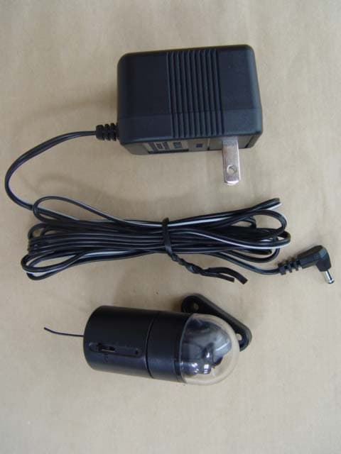
Click to zoom
Application Details
- Equipment Class
- DXX - Part 15 Low Power Communication Device Transmitter
- Date of Grant
- Sep 27, 2004
- Application Purpose
- Original Equipment
- Date of Application
- Sep 27, 2004
- Equipment Note
- Wireless Control Security/Alarm Transmitter Camera
- Frequency Range
- 2414.00000000 - 2468.00000000
- Company
- Actwell Technology Inc.
- Country
- Taiwan
Documents & Files
Document Text
Text extracted from the exhibit documents filed with the FCC. Open a document above to read the original.
Users Manual
~, FeCEO681(i)I ... Edition Firstedition,September2004 Copyrightinformation ',\ Thispublication,includingallphotographs,illustrationsandsoftware,is protectedunderinternationalcopyrightlaws,withallrightsreserved.Neitherthis manual,noranyofthematerialcontainedherein,maybereproducedwithout writtenconsentoftheauthor. .~.\ .~@September,2004 '-<. Trademarks Allproductnamesusedinthismanualarethepropertiesoftheirrespective ownersandareacknowledged. '>"":: .. - Safetyandbatteryuse .Readandfollowanywarningsinthismanual. . Readtheregulatorycompliancenoticeonpage22. Whennotin use,removeanybatteriesandstorethemina cooldryplace. . . Donotusethecameraintemperaturesbelow-10orexceeding55degrees Celsius . Don'tdisposeofusedbatterieswithhouseholdwaste.Returnthebatteriesto yourdealerortoa specialdisposalservice. Anyservicingmustonlybedonebyqualifiedpersonnel. . . Donotsetuporusethereceiverorcameraina wetordampenvironment. Savetheseinstructionsforfuturereference. . About thismanual Thismanualis designedtoassistuserswithsettingupandoperating#ACT-203TX /#ACT-205TX2.4GHzwirelessremotesecurityalarmcamerasystem. Informationinthisdocumenthasbeencarefullycheckedforaccuracy;however, noguaranteeisgivenastothecorrectnessofthecontents.Theinformation containedinthisdocumentis subjecttochangewithoutnotice. 11 Tableofcontents I-GETTINGSTARTED1 CHECKINGTHEPACKINGLIST1 IDENTIFYINGPARTS3 Camera3 Receiver 4 2-SETTINGUP:"""""""""""""""""5 PRE-SETUPTESTING5 MAKINGCONNECTIONS6 Receiversetup6 ConnectingtheACadaptertothecamera7 Connectingthebatterytothecamera7 MOUNTINGOPTIONS8 Ceilinginstallation8 Wallinstallation9 Hiddeninstallation12 ADJUSTINGTHECAMERAANGLE14 3-0PERATION15 OPERATINGRESTRICTIONS,15 MATCHINGCHANNELS16 STANDARDALWAYS-ONOPERATION"16 REEDSWITCHOPERATION"""""""""""""""""""""""""""""'"17 Reedswitchinstallation17 SettoNO(NormalOpen)17 SettoNC(NormalClosed)17 R/CCABLEOPERATION,18 SWITCHINGAUDIOOUTPUT18 iii APPENDIX..19 CLEANING,19 TROUBLESHOOTING,19 TECHNICALSPECIFICATIONS21 Camera21 Receiver21 FEDERALCOMMUNICATIONSCOMMISSION(FCC)STATEMENT22 WARRANTY,'23 IV 1-Gettingstarted Congratulationsonyourpurchaseoftheremotecamera.Usethiscameratomonitor locationswirelessly,asa stand-alonesolutionorintegratedintoanexistingalarm system. Checkingthepackinglist Carefullyunpacktheprojectorandcheckthatthefollowingitemsareincluded: $i Receiver Camerawithdomecover ReceiverACadapter CameraACadapter RlCcableSensorcable -- I-GETTINGSTARTED Checkingthepackinglist(continued) A/Vcable Wallmounts 2 @ tJ ..<t,;";,, ff) 9V-batteryadapter Hiddenmounts !f . ~n)/f}) ~/Iil# 000 Ceilingmountsand foamspacers (11 .,4 . " . ~ 7" .~ Audioterminator ~I~ ~ Reedswitch IDENTIFYINGPARTS Identifyingparts Camera Refertothefollowingsectionstoidentifycomponentsofthecameraandreceiver. 8 1 CHili; 4 7 . J 1 2 3 4 5 6 3 Item Description Seepage 1. Antenna - 2. DCINjack 7 3. NONCswitch17 4. R/CINsensorjack 18 5.Domecover 5 6. Camera(underdomecover) 14 7. Microphone - 8.CH1-4channelswitch 16 I-GETTINGSTARTED Receiver ~ Mcif@!J t4GJI1-f'I~ ." ':':/:::' ~ '::::': IJ ':/:' . .::., /" 1 4 Item Description Seepaqe 1. Speaker - 2. Socketmount - 3. Volumeslider 18 4. R/COUTjack 18 5. AVOUTjack 6 - 6. DCINjack 6 7.CH1-4channelswitch 16 8. ONpowerLED - 2-Settingup Thissectionexplainsthemountingoptionsandsetupoftheremotecamera.However, beforeinstallingthecameracheckthatallthepartsareworkingasdescribedbelow. Pre-setuptesting Forthepre-setuptestdothefollowing: . ConnecttheANcablefromthereceivertothemonitor.Ensurethemonitor is setforvideoplayback. Connectthesensorcablefromthecameratothereedswitch. . . ConnecttheACadapters. Matchthechannelsonthereceiverandcamera. . '~ ~ : . CH3 4 . r?\\'251"'j] f&\(g\(GY ."",°'i [\J1 ~~J 1;1f" I~ CH . Checkthatvideoandsoundareavailableonthemonitor. 2-SETTINGUP . Testthesensoroperationbymovingthereedswitchapartandchangingthe NONCsettingonthecamera. Ifsomefunctionsdonotwork,checkthecorrespondingsectioninthis manualbeforeinstallingthecamera. . Makingconnections Thereceiveris designedtoconnecttodifferentdevicessuchasa TV,VCR,ordigital videorecorder(DVR). ReceiversetuQ ~~~ twO'"i . ConnecttheAVcabletoa TVmonitor,VCR,DVR,orcomputer(needanAN graber). ConnecttheACadaptertoa poweroutlet. ConnecttheR/Ccabletoa videorecordingdeviceswitch,DVR,or externalalarm. . . 6 MAKINGCONNECTIONS ConnectinatheACadaptertothecamera UseonlythesuppliedACadapter. Connectinathebatterytothecamera Usea 9Vbattery. 7 2-SETTINGUP Mountingoptions Usingthesuppliedaccessories,thecameracanbemountedona ceilingorwall.It can alsobemountedina hiddenlocationsuchasina containerorbehinda partition. Important: Thedomecoverholdsthecamerahousingtogether.Whenyou removethedomecover,takecarethatthecamerahousingdoes notseparate. Ceilinginstallation Beforechoosinga locationfortheceilinginstallation,considerthefollowing: . Youmayneedtoinstallthecamerafromabove,in whichcasetwoadjacent tilesneedtoberemovedfortheinstallation. . Youmustholdthecamerainpositionfromabovetheceilingtilewhile screwingthedomecoveron. Youmayneedtoadjustthecameraanglebeforereplacingtheadjacenttile. . . Youneeda powersourceforthecamera. Refertothefollowingfortheceilinginstallation. 1. Removethedomecoverfromthecamera. 2. Cuta 27-mmdiameterholeina ceilingtilewitha circlecutter. (Usea spadebittodrilla holeina woodpanel.) Putthecamerainfromthetop. 3. rt l '91 ;~1i ~";Q 8~ <e: 8 MOUNTINGOPTIONS 4. Usefoamspacerstoensurethedomecoverscrewsonsecurely.A thinnerceilingtilemayrequiremorethanonefoamring;a thicker ceilingtilemayrequirenoneat all. Adjustthecameraangle.(See"Adjustingthecameraangle"on page14.) 5. 6. Screwthedomecoverontothecamera. Wallinstallation Beforechoosinga locationforthewallinstallation,considerthefollowing: .Youneeda powersourceforthecamera.Checkthatthecablelengthonthe suppliedACadapteris longenoughtoreachyourpowersourcebefore drillingholes. . Doesthelocationyouchoosetoinstallthecameraalloweasyaccesstothe camera?Thecameradomemustberemovedandthecameratakenoutofthe wallbrackettoconnecttoDCINandR/CIN. Thewallbracketisdesignedsothat…
Text truncated - open the document above for the full version.
Users Manual
MOUNTINGOPTIONS G",=-.. G, ~~ cfl ""IIJ ~',~" . ". ! ~ ' , " . '~ ~".,:' "V"-:'1'~ ~, "'~ 7. Forsoftmaterialssuchaswoodskiptostep9. Forconcrete,brick,orstonesurfaces,drillholes23mmdeepwitha 6-mmbit. Putthewallplugsintotheholes. 8. 9. Screwthemountingbrackettothewall. Slidethemountingringintothemountingbracketuntilit clicksinto place. Toremovethewallmount: 10. 1. Removethedomecoverandtakethecameraoutofthemounting ring. Toremovethemountingring,pressthecatchonthewallbracketwith a flat-tippedscrewdriverandpushthemountingringupward. 2. 3. Removethethreescrewstoremovethewallmount. II 2-SETTINGUP Hiddeninstallation Thecameracanbeconcealedina varietyoflocationssuchasbehinda thinpartition orinsidea suitcase. Note: Drilla 6.3mmdiameterholein thesurfaceyouwanttomountthecamera behind.Topreventthecameraviewfrombeingobscured,thesurface thatthecamerais behindmustnotexceed3 mminthickness. Thefocusonthecameraisfactoryadjustedtoallowforviewingthroughthedome cover,Whenusedwithoutthedomecover,youmustreadjustthefocusaccordingly. Refertothefollowingtomountthecameraina hiddenlocation. 1. Removethedomecover. ~ ("'; d. "".(::) '£IT 2. Adjustthefocusbyturningthelens. -(@'~1(qf 3. Screwthehiddenmountontothecamera. 12 MOUNTINGOPTIONS ~'~i(a).. 4. Removethebackingpaperfromonesideoftheadhesivepad. ~'.10"~.. @ 5. Aligntheholesandpresstheadhesivepadontothemountingring. 6. Removethebackingpaperfromtheothersideoftheadhesivepad. 7. Aligntheholesandpressthecameratothesurface. 13 2-SETTINGUP Adjustingthecameraangle Thecameracanonlybetiltedinonedirection90degreesandrotated360degrees. Adjustthecameragently.If it doesnotmoveeasily,moveit in theotherdirection. Note: Thefocusonthecameraisfactoryadjustedtoallowforviewingthrough thedomecover.Onlyadjustthefocuswhenusingthecamerawithout thedomecover. 14 3-0peration Thechapterdescribestheoperationoftheremotecamera. Operatingrestrictions .Onlyuse9Vbatterieswiththeadapter. . Avoidusingthecamerainhumidlocations.If condensationoccurs,allowthe cameratodrybeforeoperating. Donotuseintemperaturesbelow-10degreesCelsiusorabove55degrees Celsius. . . Proximitytomicrowaveovenscancauseinterferenceandreducethequality oftheaudioandvideosignals. Usingtwocamerasin thesamevicinitymayresultinsoundandpicture interference. . 3-0PERATION Matchingchannels Acameraandreceivertogetherforma camera/receiverpair.Seta pairedcameraand receivertothesamechannel.Ifyouareusingtwoormorecamera/receiverpairsbe surethateachpairis settodifferentchannelsortherewillbeinterference. Uptofourcamerascanbeusedwithonereceiver.Eachcameramustbesettoa differentchannel.Videofromeachcameracanthenbeviewedinturnbychangingthe channelonthereceiver. 0 ON -I; @ @) ~ ,"~j Standardalways-onoperation StandardoperationallowscontinuousaudioandvideosignalsITomthecameratothe receiver.Thevideoismonitoredona screenbutnotrecorded.Audioismonitored throughtheAVdevicethatisconnectedtothereceiver.(Orthroughthereceiver speakerwhentheaudioterminatoris used.) 16 REEDSWITCHOPERATION Reedswitchoperation Areedswitchisa magneticallyactivated switch.Thereedswitchcanbeusedwiththe sensorcablefordetectingentrythroughdoors andwindows.Thesensorcableplugsintothe reedswitchandtheRlCINconnectoronthe camera.TheNONCswitchstandsfor NormalOpen/NormalClosedandrefersto thestatusofthesensor. DCIN @) NO II NC Q) N Note: Thesensorcablecanbeattachedtoothertriggersasrequired. Reedswitchinstallation Insertthesensorcablewiresintothereedswitchandsecurethembytighteningthe screws. SettoNO(NormalOpen) SettheNONCswitchtoNOandsetupthereedswitchona window.Whenthe windowis closedthealarmsoundsonthereceiver. SettoNC(NormalClosed) SettheNONCswitchtoNCandsetupthereedswitchona window.Whenthe windowis openedthealarmsoundsonthereceiver. 17 3--OPERATION RICcableoperation TheR/Ccableis a relayconnectingcable,whichallowsrecordingofaudioandvideo tobetriggeredbyanalannsuchasthesuppliedreedswitch.Thisfunctionsaves recordingspaceasrecordingonlybeginsafteraneventsuchasa dooropeningor closing. TheR/Ccableisconnectedtothe receiverandtoa videorecorder.When thereedswitchistriggeredatthecamera location,theR/Ccablethentriggersthe videorecordertobeginrecording.(For connectingtheR/Ccabletoa video recorder,seetherecorder'susermanual.) Note: Anexternalalann(notsupplied)canbeused. Switchingaudiooutput Theaudiotenninatorforcesaudiofromthemicrophoneandalanntothereceiver speaker.Thevolumecontrolonthereceiveronlyaffectsthevolumeonthereceiver andnota connectedTVorothervideodevice. PlugtheredaudioRCAjackfromtheAV cableintotheaudiotenninator. Adjustthevolumeaccordingly. 18 ~~ @ + 4. Appendix Thisappendixdescribescleaningandtroubleshootingprocedures.Alsocoveredare technicalspecifications,FCCcompliance,andwarrantyinformation. Cleaning Thelenscanbewipedwitha softopticalcleaningcloth.Thedomecovercanbe cleanedwithglasscleaner. Troubleshooting Thereis nopicture onthescreen. 1. Makesurepowercablesarepluggedinproperly andthattheoutletshavepower. Ensurethebatteryonthecameraisfresh. Makesurethatthereceiveris pluggedin. CheckthattheA Vcablesareproperlyconnected. Ifusinga television,makesurethatthecorrect videochannelis selected. Makesurethatthecameraandthereceiverareon thesamefrequencychannel. Ensurethatthereceiveriswithinthetransmitting rangeof300meters(inL-O-S). 2. 3. 4. 5. 6. 7. ;. ApPENDIX 20 Thepicture 1. Ensurethebatteryonthecamerais fresh. qualityis poor. 2. Makesurethatnothingis obstructingthecamera. 3. Don'tusethecameraneara microwaveoven. 4. Makesurethereis sufficientlight. 5. Don'tusemorethanonecamerainthesame vicinity. Thereis a picture 1. Checkthevolumeonthereceiverandtheaudio butnosound.device. 2. Ensurethebatteryonthecamerais fresh. 3. Checkthattheaudiocableis properlypluggedinto thereceiverandtheaudiodevice. 4. Checkthattheaudioterminator(ifused)is securely pluggedin. Thereis soundbut 1. Ensurethebatteryonthecamerais fresh. nopicture. 2. Checkthatthevideocableis properlyconnectedto thereceiverandthemonitor. 3. Checkthebrightnessonthedisplay. Thealarmdoes1. Makecertainthesensorcableis pluggedinandthat notturnofforon. th…
Text truncated - open the document above for the full version.
Cover Letter(s)
ACTWELLTECHNOLOGYINC. 2F.No.l6.Lane609.Sec.S.ChunghsinRd..SanchungCity,Taipei.Taiwan241 Phone:0222787378Fax: 0222787363E mail:[email protected] 4ctwell Teclino{o1'J FederalCommunicationsCommission DearSir: We,theundersigned,herebyauthorizeETSDr.GenzTaiwanPSCo.,Ltd.to act onourbehalfinallmattersrelatingtoapplicationfor"WirelessRemoteControl SecurityIAlarmANTransmitterCamera( Model:ACT-203TX, FCCID: SB2ACT-203TX)"authorization,includingthesigningofall documentsrelatingto thesematters.AnyandallactscarriedoutbyETSDr.Genz TaiwanPSCo.,Ltd.onourbehalfshallhavethesameeffectasactsofourown. Theapplicantcertifiesthatin thecaseofanindividualapplicant( e.g.,corporation), nopartyto theapplicantis subjecttoa denialoffederalbenefits,thatincludesFCC benefits,pursuanttosection5301oftheAnti-drugabuseActof1988,21V.S.C.862. Fora definitionofa "party"forthesepurposesSee47C.F.R.1.2002(b). -'.- By: ~Q~/Jd~~-~,,',,,:'By: (Signature)-,.0':'"tc..,<,' Title: Manager SusanTsai (printed) Applicant:ACTWELLTECHNOLOGYINC. Address:2F,No.16,Lane609,ChungHsinRd.,Sec.5,SanChungCity,TaipeiHsien, Taiwan,RO.C. Tel:+886-2-2278-7378Fax:+886-2-2278-7363 Date : JulY..Q2,2004
External Photos
Registration number : W6M20405-5167-P-15B ELECTRONIC TECHNOLOGY SYSTEMS DR. GENZ GMBH STORKOWER STRASSE 38C D-15526 REICHENWALDE B. BERLIN ELECTRONIC TECHNOLOGY SYSTEMS DR.GENZ GMBH External Photo Registration number : W6M20405-5167-P-15B ELECTRONIC TECHNOLOGY SYSTEMS DR. GENZ GMBH STORKOWER STRASSE 38C D-15526 REICHENWALDE B. BERLIN ELECTRONIC TECHNOLOGY SYSTEMS DR.GENZ GMBH Registration number : W6M20405-5167-P-15B ELECTRONIC TECHNOLOGY SYSTEMS DR. GENZ GMBH STORKOWER STRASSE 38C D-15526 REICHENWALDE B. BERLIN ELECTRONIC TECHNOLOGY SYSTEMS DR.GENZ GMBH Registration number : W6M20405-5167-P-15B ELECTRONIC TECHNOLOGY SYSTEMS DR. GENZ GMBH STORKOWER STRASSE 38C D-15526 REICHENWALDE B. BERLIN ELECTRONIC TECHNOLOGY SYSTEMS DR.GENZ GMBH Registration number : W6M20405-5167-P-15B ELECTRONIC TECHNOLOGY SYSTEMS DR. GENZ GMBH STORKOWER STRASSE 38C D-15526 REICHENWALDE B. BERLIN ELECTRONIC TECHNOLOGY SYSTEMS DR.GENZ GMBH Registration number : W6M20405-5167-P-15B ELECTRONIC TECHNOLOGY SYSTEMS DR. GENZ GMBH STORKOWER STRASSE 38C D-15526 REICHENWALDE B. BERLIN ELECTRONIC TECHNOLOGY SYSTEMS DR.GENZ GMBH Registration number : W6M20405-5167-P-15B ELECTRONIC TECHNOLOGY SYSTEMS DR. GENZ GMBH STORKOWER STRASSE 38C D-15526 REICHENWALDE B. BERLIN ELECTRONIC TECHNOLOGY SYSTEMS DR.GENZ GMBH Registration number : W6M20405-5167-P-15B ELECTRONIC TECHNOLOGY SYSTEMS DR. GENZ GMBH STORKOWER STRASSE 38C D-15526 REICHENWALDE B. BERLIN ELECTRONIC TECHNOLOGY SYSTEMS DR.GENZ GMBH Registration number : W6M20405-5167-P-15B ELECTRONIC TECHNOLOGY SYSTEMS DR. GENZ GMBH STORKOWER STRASSE 38C D-15526 REICHENWALDE B. BERLIN ELECTRONIC TECHNOLOGY SYSTEMS DR.GENZ GMBH
ID Label/Location Info
10 mm 8 mm Model No.: ACT-203TX FCC ID : SB2ACT-203TX
Internal Photos
Registration number : W6M20405-5167-P-15B ELECTRONIC TECHNOLOGY SYSTEMS DR. GENZ GMBH STORKOWER STRASSE 38C D-15526 REICHENWALDE B. BERLIN ELECTRONIC TECHNOLOGY SYSTEMS DR.GENZ GMBH Internal Photo Registration number : W6M20405-5167-P-15B ELECTRONIC TECHNOLOGY SYSTEMS DR. GENZ GMBH STORKOWER STRASSE 38C D-15526 REICHENWALDE B. BERLIN ELECTRONIC TECHNOLOGY SYSTEMS DR.GENZ GMBH Registration number : W6M20405-5167-P-15B ELECTRONIC TECHNOLOGY SYSTEMS DR. GENZ GMBH STORKOWER STRASSE 38C D-15526 REICHENWALDE B. BERLIN ELECTRONIC TECHNOLOGY SYSTEMS DR.GENZ GMBH Registration number : W6M20405-5167-P-15B ELECTRONIC TECHNOLOGY SYSTEMS DR. GENZ GMBH STORKOWER STRASSE 38C D-15526 REICHENWALDE B. BERLIN ELECTRONIC TECHNOLOGY SYSTEMS DR.GENZ GMBH Registration number : W6M20405-5167-P-15B ELECTRONIC TECHNOLOGY SYSTEMS DR. GENZ GMBH STORKOWER STRASSE 38C D-15526 REICHENWALDE B. BERLIN ELECTRONIC TECHNOLOGY SYSTEMS DR.GENZ GMBH Registration number : W6M20405-5167-P-15B ELECTRONIC TECHNOLOGY SYSTEMS DR. GENZ GMBH STORKOWER STRASSE 38C D-15526 REICHENWALDE B. BERLIN ELECTRONIC TECHNOLOGY SYSTEMS DR.GENZ GMBH Registration number : W6M20405-5167-P-15B ELECTRONIC TECHNOLOGY SYSTEMS DR. GENZ GMBH STORKOWER STRASSE 38C D-15526 REICHENWALDE B. BERLIN ELECTRONIC TECHNOLOGY SYSTEMS DR.GENZ GMBH
Operational Description
ACT-203TX Operational Description 1. The audio signal is picked up by the MIC and is mixed with a tone of 32.768kHz. The mixed signal then is sent to the amplifier circuit consisted of two NPN-type transistors. 2. The amplified signal is fed into the 5.5 MHz modulator for audio modulation. 3. The modulated audio signal then is sent to a mixer for mixing with the video signal coming from CCD camera. 4. The mixed audio and video signals finally are transmitted out with the antenna via 2.4GHz RF amplifier.
Test Report
ELECTRONIC TECHNOLOGY SYSTEMS DR. GENZ GMBH FCC TEST - REPORT FCC RULES PART 15 / SUBPART C § 15.249 FCC ID : SB2ACT-203TX Test report no.: W6M20405-5167-P-15 ELECTRONIC TECHNOLOGY SYSTEMS STORKOWER STRASSE 38C, D-15526 REICHENWALDE B. BERLIN DR. GENZ GMBH PHONE +49-33631-888 00 FAX +49-33631-888 66 ELECTRONIC TECHNOLOGY SYSTEMS DR.GENZ GMBH Registration number: W6M20405-5167-P-15 FCC ID: SB2ACT-203TX ETS Dr. Genz GmbH, Germany 1 of 26 TABLE OF CONTENTS 1 GENERAL INFORMATION ................................................................................................... 2 1.1 N OTES ................................................................................................................................... 2 1.2 T ESTING LABORATORY ......................................................................................................... 3 1.2.1 Location .......................................................................................................................3 1.2.2 Details of accreditation status ..................................................................................... 3 1.3 D ETAILS OF APPROVAL HOLDER ............................................................................................ 3 1.5 G ENERAL INFORMATION OF T EST ITEM ................................................................................. 4 T ECHNICAL DATA .............................................................................................................................. 4 1.6 T EST STANDARDS .................................................................................................................. 5 2 TECHNICAL TEST ..................................................................................................................6 2.1 S UMMARY OF TEST RESULTS ................................................................................................. 6 2.2 T EST ENVIRONMENT.............................................................................................................. 6 2.3 T EST E QUIPMENT L IST .......................................................................................................... 7 2.4 G ENERAL T EST P ROCEDURE ............................................................................................... 14 3 TEST RESULTS (ENCLOSURE).......................................................................................... 15 3.1 P EAK O UTPUT P OWER ( TRANSMITTER ) ............................................................................... 16 3.2 E QUIVALENT ISOTROPIC RADIATED POWER ......................................................................... 17 3.2.1 Transmitter................................................................................................................. 17 3.3 RF E XPOSURE COMPLIANCE REQUIREMENTS..................................................................... 17 3.4 O UT OF B AND R ADIATED E MISSIONS .................................................................................. 17 3.6 R ADIATED E MISSION ON THE BANDEDGE ............................................................................ 20 3.7 P OWER L INE C ONDUCTED E MISSION .................................................................................. 21 APPENDIX................................................................................................................................22 A PPENDIX A.................................................................................................................................... 23 A PPENDIX B .................................................................................................................................... 24 A PPENDIX C .................................................................................................................................... 25 A PPENDIX D.................................................................................................................................... 26 ELECTRONIC TECHNOLOGY SYSTEMS DR.GENZ GMBH Registration number: W6M20405-5167-P-15 FCC ID: SB2ACT-203TX ETS Dr. Genz GmbH, Germany 2 of 26 1 General Information 1.1 Notes The purpose of conformity testing is to increase the probability of adherence to the essential requirements or conformity specifications, as appropriate. The complexity of the technical specifications, however, means that full and thorough testing is impractical for both technical and economic reasons. Furthermore, there is no guarantee that a test sample which has Passed all the relevant tests conforms to a specification. Neither is there any guarantee that such a test sample will interwork with other genuinely open systems. The existence of the tests nevertheless provides the confidence that the test sample possesses the qualities as maintained and that is performance generally conforms to representative cases of communications equipment. The test results of this test report relate exclusively to the item tested as specified in 1.5. The test report may only be reproduced or published in full. Reproduction or publication of extracts from the report requires the prior written approval of the ELECTRONIC TECHNOLOGY SYSTEMS DR. GENZ GMBH. Tester: 29.07.2004 Ralf Schultze Date ETS-Lab. Name Signature Technical responsibility for area of testing: 29.07.2004 N. Kasper Date ETS Name Signature ELECTRONIC TECHNOLOGY SYSTEMS DR.GENZ GMBH Registration number: W6M20405-5167-P-15 FCC ID: SB2ACT-203TX ETS Dr. Genz GmbH, Germany 3 of 26 1.2 Testing laboratory 1.2.1 Location ELECTRONIC TECHNOLOGY SYSTEM DR. GENZ GMBH (ETS) Storkower Straße 38c D-15526 Reichenwalde b. Berlin Germany Telefon : +49 33631 888 00 Telefax : +49 33631 888 660 1.2.2 Details of accreditation status Accredited testing laboratory DAR- REGISTRATION NUMBER : TTI-P-G 126/96 Accredited Competent Body DAR- REGISTRATION NUMBER: BPT-ZE-026/96 FCC FILED TEST LABORATORY REG. NO. 96970 B LUETOOTH QUALIFICATION TEST FACILITY (BQTF)…
Text truncated - open the document above for the full version.
Test Setup Photos
Registration number : W6M20405-5167-P-15B ELECTRONIC TECHNOLOGY SYSTEMS DR. GENZ GMBH STORKOWER STRASSE 38C D-15526 REICHENWALDE B. BERLIN ELECTRONIC TECHNOLOGY SYSTEMS DR.GENZ GMBH Set Up Photo Registration number : W6M20405-5167-P-15B ELECTRONIC TECHNOLOGY SYSTEMS DR. GENZ GMBH STORKOWER STRASSE 38C D-15526 REICHENWALDE B. BERLIN ELECTRONIC TECHNOLOGY SYSTEMS DR.GENZ GMBH Registration number : W6M20405-5167-P-15B ELECTRONIC TECHNOLOGY SYSTEMS DR. GENZ GMBH STORKOWER STRASSE 38C D-15526 REICHENWALDE B. BERLIN ELECTRONIC TECHNOLOGY SYSTEMS DR.GENZ GMBH Registration number : W6M20405-5167-P-15B ELECTRONIC TECHNOLOGY SYSTEMS DR. GENZ GMBH STORKOWER STRASSE 38C D-15526 REICHENWALDE B. BERLIN ELECTRONIC TECHNOLOGY SYSTEMS DR.GENZ GMBH Registration number : W6M20405-5167-P-15B ELECTRONIC TECHNOLOGY SYSTEMS DR. GENZ GMBH STORKOWER STRASSE 38C D-15526 REICHENWALDE B. BERLIN ELECTRONIC TECHNOLOGY SYSTEMS DR.GENZ GMBH Registration number : W6M20405-5167-P-15B ELECTRONIC TECHNOLOGY SYSTEMS DR. GENZ GMBH STORKOWER STRASSE 38C D-15526 REICHENWALDE B. BERLIN ELECTRONIC TECHNOLOGY SYSTEMS DR.GENZ GMBH Registration number : W6M20405-5167-P-15B ELECTRONIC TECHNOLOGY SYSTEMS DR. GENZ GMBH STORKOWER STRASSE 38C D-15526 REICHENWALDE B. BERLIN ELECTRONIC TECHNOLOGY SYSTEMS DR.GENZ GMBH Registration number : W6M20405-5167-P-15B ELECTRONIC TECHNOLOGY SYSTEMS DR. GENZ GMBH STORKOWER STRASSE 38C D-15526 REICHENWALDE B. BERLIN ELECTRONIC TECHNOLOGY SYSTEMS DR.GENZ GMBH Registration number : W6M20405-5167-P-15B ELECTRONIC TECHNOLOGY SYSTEMS DR. GENZ GMBH STORKOWER STRASSE 38C D-15526 REICHENWALDE B. BERLIN ELECTRONIC TECHNOLOGY SYSTEMS DR.GENZ GMBH Registration number : W6M20405-5167-P-15B ELECTRONIC TECHNOLOGY SYSTEMS DR. GENZ GMBH STORKOWER STRASSE 38C D-15526 REICHENWALDE B. BERLIN ELECTRONIC TECHNOLOGY SYSTEMS DR.GENZ GMBH Registration number : W6M20405-5167-P-15B ELECTRONIC TECHNOLOGY SYSTEMS DR. GENZ GMBH STORKOWER STRASSE 38C D-15526 REICHENWALDE B. BERLIN ELECTRONIC TECHNOLOGY SYSTEMS DR.GENZ GMBH Registration number : W6M20405-5167-P-15B ELECTRONIC TECHNOLOGY SYSTEMS DR. GENZ GMBH STORKOWER STRASSE 38C D-15526 REICHENWALDE B. BERLIN ELECTRONIC TECHNOLOGY SYSTEMS DR.GENZ GMBH Registration number : W6M20405-5167-P-15B ELECTRONIC TECHNOLOGY SYSTEMS DR. GENZ GMBH STORKOWER STRASSE 38C D-15526 REICHENWALDE B. BERLIN ELECTRONIC TECHNOLOGY SYSTEMS DR.GENZ GMBH Registration number : W6M20405-5167-P-15B ELECTRONIC TECHNOLOGY SYSTEMS DR. GENZ GMBH STORKOWER STRASSE 38C D-15526 REICHENWALDE B. BERLIN ELECTRONIC TECHNOLOGY SYSTEMS DR.GENZ GMBH Registration number : W6M20405-5167-P-15B ELECTRONIC TECHNOLOGY SYSTEMS DR. GENZ GMBH STORKOWER STRASSE 38C D-15526 REICHENWALDE B. BERLIN ELECTRONIC TECHNOLOGY SYSTEMS DR.GENZ GMBH
Contact Information
Applicant
Susan Tsai(Manager)
Technical Contact
ETS Dr. Genz TAIWAN PS CO., LTDSteven Chuang
[email protected]+886-2-6606-8877
6F., No. 58, Lane 188, Ruey Kuang Road, Neihu · Taipei · Taiwan
Non-Technical Contact
ETS Dr. Genz TAIWAN PS CO., LTDLulu Lin
[email protected]+886-2-6606-8877
Test Firm
Eurofins Product Service GmbHRobert Kschiwan-Kaspar
Technical Specifications
| # | Rule Parts | Frequency Range | Power Output |
|---|---|---|---|
| 1 | 15C | 2.41 GHz - 2.47 GHz | - |
Other Applications from Actwell Technology Inc.
SB2ACT-202TX
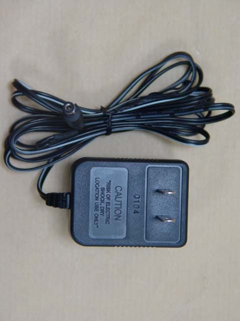
Sep 27, 2004Wireless Security A/V Transmitter Camera
Equipment Class
DXX - Part 15 Low Power Communication Device Transmitter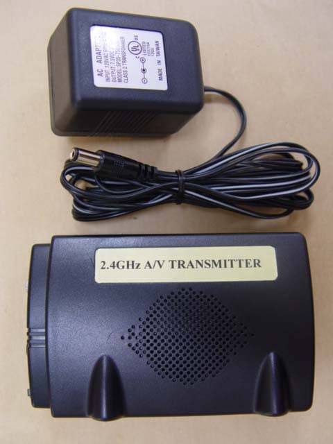
SB2ACT-205TX
Sep 27, 2004Wireless Control Security/Alarm A/V Transmitter
Equipment Class
DXX - Part 15 Low Power Communication Device Transmitter