SB7AAALOW POWER TRANSMITTER FOR ANY REMOTE CONTROL
Next Generation Home Products Inc.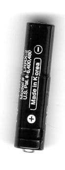
Click to zoom
Application Details
- Equipment Class
- DSC - Part 15 Security/Remote Control Transmitter
- Date of Grant
- Jul 27, 2004
- Application Purpose
- Original Equipment
- Date of Application
- Jul 27, 2004
- Equipment Note
- LOW POWER TRANSMITTER FOR ANY REMOTE CONTROL
- Frequency Range
- 433.00000000 - 434.00000000
- Country
- United States
Documents & Files
Document Text
Text extracted from the exhibit documents filed with the FCC. Open a document above to read the original.
Users Manual
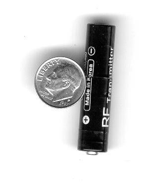
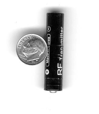
Around The House Remote Extender Owners Manual—Please read before using this equipment Thank you for buying the Around The House Remote Extender with AAA size transmitter and AA size sleeve, which extends your existing remote controls operating range. The extender allows your remote to operate your electronics components and not worry about line of sight requirements. The AAA size battery transmitter (or AA size sleeve) is installed inside your remote control’s battery compartment. The transmitter converts the remote control keypad signal RF. The receiver senses these transmissions, Converts them back to IR signals, and then relays them to your audio and video equipment. Installation Installing the transmitter 1. Remove the tab from the AAA battery transmitter. Push battery all the way into the sleeve. 2.Replace one of the AAA batteries inside tour remote with the AAA transmitter. Note: If your remote control uses AA batteries, insert the AAA transmitter into the supplied sleeve. If signal seems week you may need to move the transmitter to another battery slot in your remote. Installing the Receiver 1. Place the receiver in front of the audio/ video and position it: With in 10m (30 ft.) of the audio/video equipment’s Remote sensor Where the front of the receiver directly faces the audio/video remote sensor 2. Fully extend the antenna. 3. Connect the supplied AC/DC adapter’s barrel plug into receivers DC 12V jack, and then connect the adapter’s AC plug to a standard AC outlet. 4. Remove cover on the bottom of the receiver, place extra 2/3 AAA NiMH battery (supplied in kit) in slot marked for 2/3 AAA, make sure the three way switch on the bottom is in position “B” and replace cover. Connecting the Bright Eye Emitter You can connect the supplied Bright Eye Emitter when you need to place the receiver next to your audio/video equipment instead of in front of it. 1. Insert the Bright Eye Emitter plug into the receiver IR output jack on the back of the receiver. 2. Position the Emitter bulb facing your audio/video equipment’s IR sensor. 3. Find the best position, remove the adhesive tape on the back of the bulb and stick it on front of the audio/video equipment sensor. INTERFERENCE Your extender might cause TV or radio interference even when it is operating properly. To determine whether your extender is causing the interference, turn off the extender. If the interference goes away, your extender is causing it. Try to eliminate the interference by: Moving your extender away from the receiver Connecting your extender to an outlet that is on a different electrical circuit from the receiver F.C.C. Caution This device complies with FCC rule part 15. Operation is subject to the following conditions. (1) this device may not cause harmful interference, and (2)this device must except any interference received, including interference that may cause undesired operations. Any changes or modifications not expressly approved by the party responsible for compliance could void the user's authority to operate the equipment. This device complies with RSS-210 of Industry Canada. Operation is subject to the following two conditions: (1) this device may not cause harmful interference, and (2) this device must accept any interference received, including interference that may cause undesired operation. CARE Keep the extender dry, if it gets wet wipe it dry immediately. Use and store the extender only in normal temperature environments. Handle the extender carefully; do not drop it. Keep the extender away from dust and dirt, and wipe it with a damp cloth occasionally to keep it looking new. Limited Warranty Specifications
Block Diagram
ASK SAW resonator Transmitter BLOCK DIAGRAM CIRCUIT IMFORMATION Operational Description Battery : Ni-MH(Nickel-Metal Hydride “2/3AAA” Battery, Rechargeable, Charge current(standard charging circuit) Chock1 : Line sensing Transformer ( Data Access ) coil, Axial inductor + Air Inductor(Filter) TIC1 : DC-DC(inverter switching Booster) Vin = 1.2V(2/3AAA Bat), Start-up Voltage(0.85V at 1mA), Battery Discharge rate : 85%%(0.9V/cell) TQ1 : colpitz oscillator transistor(SAW resonator base oscillator) TQ3 : CE pin enables circuit switching TR to set the standby supply current at a maximum of 5uA(Off) TQ2 : Data code sensing switching transitor TD1 : Switching Low voltage (Vf=0.2V) High current high speed Diode. TC3 : Decoupling cap(A/C pass) SAW1 : SAW resonator(fo : 433.92MHz) TL1-2 : Harmonics B.P.F filter TC4-5 : Micro strip Loop antenna PWB Component side PWB Bottom side
ID Label/Location Info
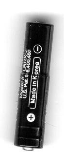
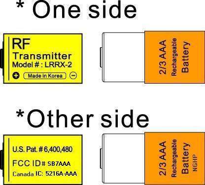
battery-1.jpg (416x376x16M jpeg)
Internal Photos
front PWB.jpg (920x638x16M jpeg) back PWB.jpg (935x643x16M jpeg)
Schematics
ASK SAW resonator Transmitter BLOCK DIAGRAM CIRCUIT IMFORMATION Operational Description Battery : Ni-MH(Nickel-Metal Hydride “2/3AAA” Battery, Rechargeable, Charge current(standard charging circuit) Chock1 : Line sensing Transformer ( Data Access ) coil, Axial inductor + Air Inductor(Filter) TIC1 : DC-DC(inverter switching Booster) Vin = 1.2V(2/3AAA Bat), Start-up Voltage(0.85V at 1mA), Battery Discharge rate : 85%%(0.9V/cell) TQ1 : colpitz oscillator transistor(SAW resonator base oscillator) TQ3 : CE pin enables circuit switching TR to set the standby supply current at a maximum of 5uA(Off) TQ2 : Data code sensing switching transitor TD1 : Switching Low voltage (Vf=0.2V) High current high speed Diode. TC3 : Decoupling cap(A/C pass) SAW1 : SAW resonator(fo : 433.92MHz) TL1-2 : Harmonics B.P.F filter TC4-5 : Micro strip Loop antenna PWB Component side PWB Bottom side
Contact Information
Applicant
Robert Dolatowski(President)
Test Firm
Product Safety Engineering, Inc.Steven Hoke
Technical Specifications
| # | Rule Parts | Frequency Range | Power Output |
|---|---|---|---|
| 1 | 15.231 | 433 MHz - 434 MHz | - |