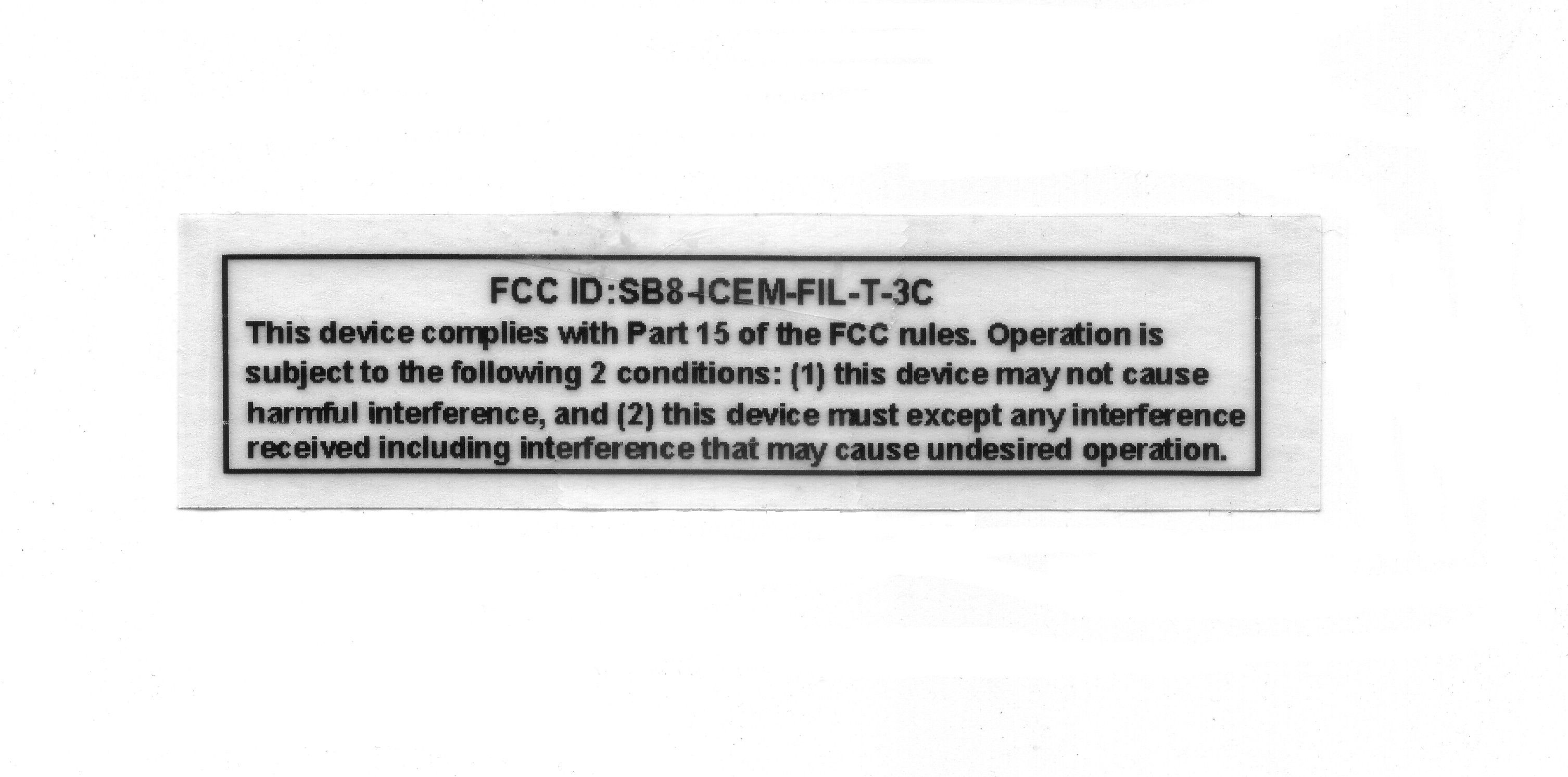
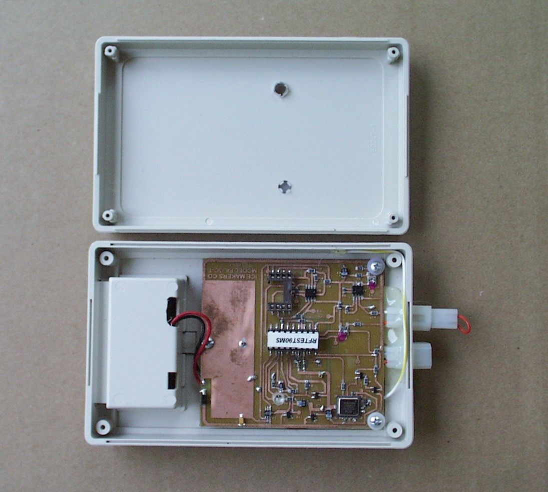
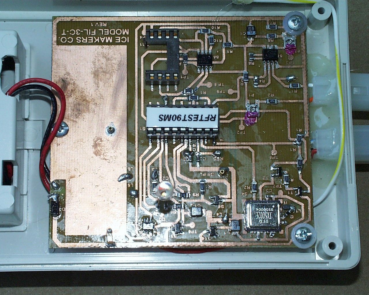
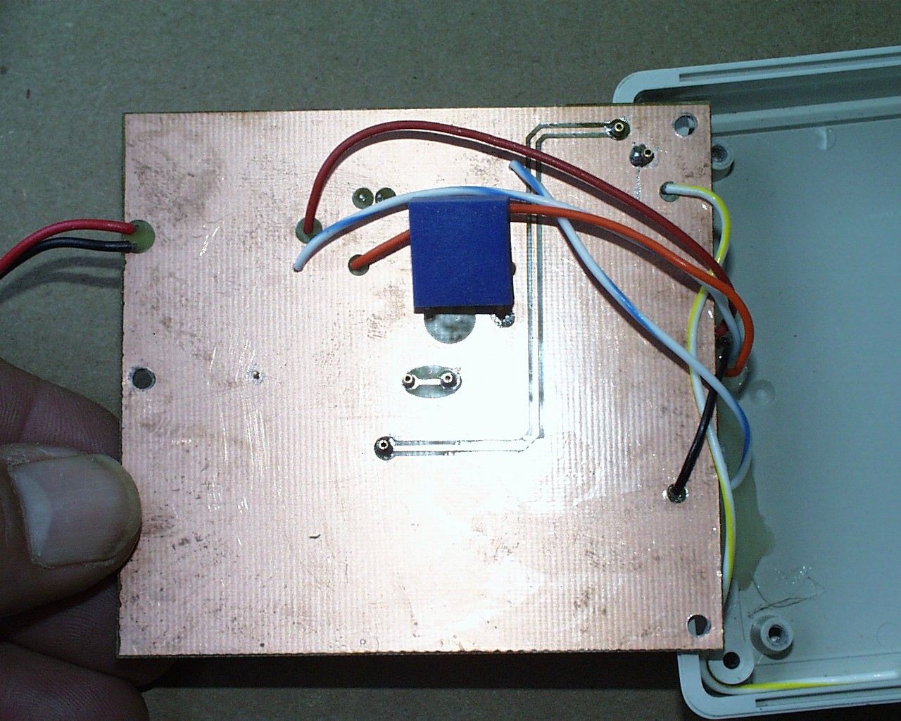
SB8-ICEM-FIL-T-3CICEMAKERS TRANSMITTER
ICEM Enterprises, Inc.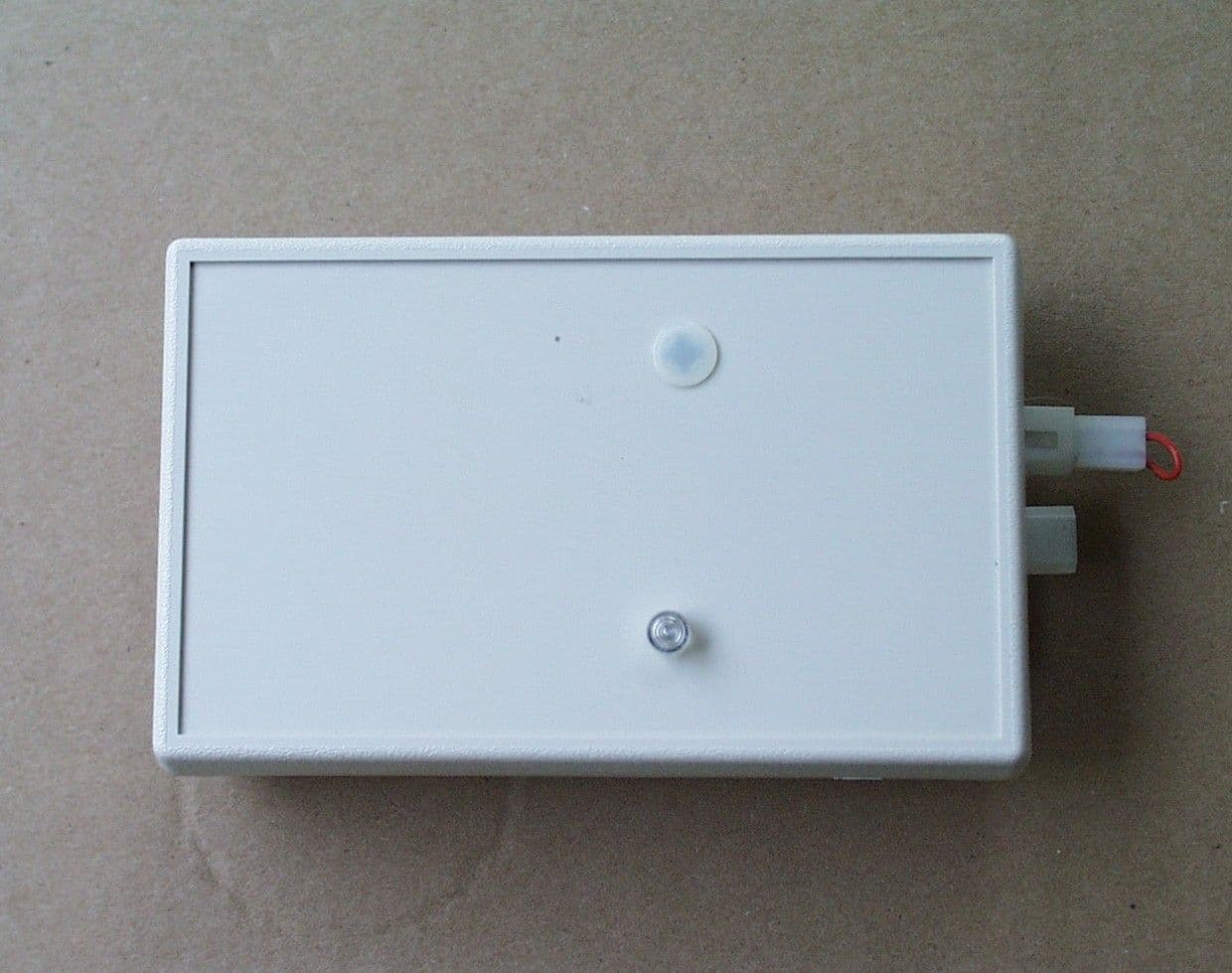
Click to zoom
Application Details
- Equipment Class
- DSC - Part 15 Security/Remote Control Transmitter
- Date of Grant
- Jul 15, 2004
- Application Purpose
- Original Equipment
- Date of Application
- Jul 15, 2004
- Equipment Note
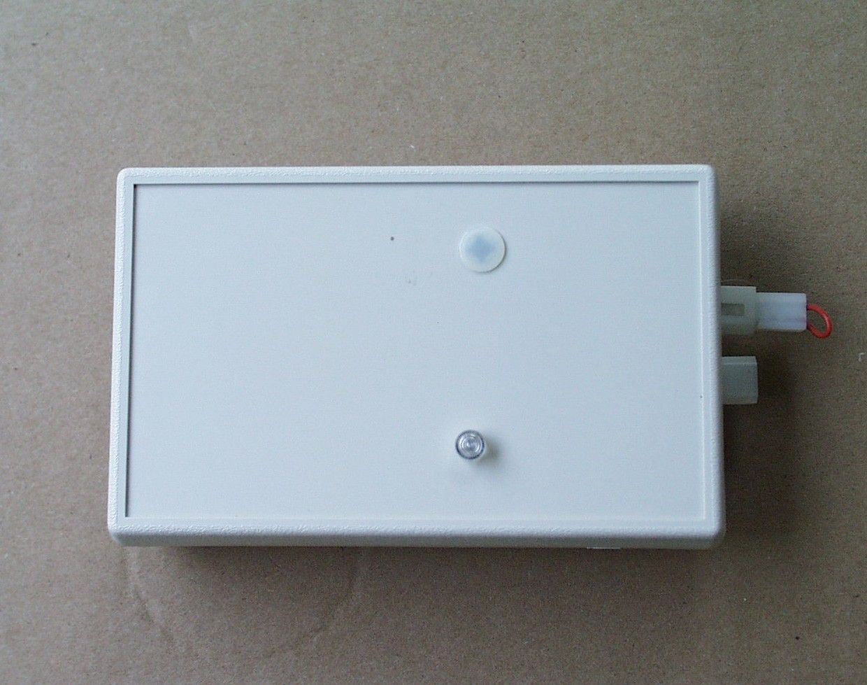
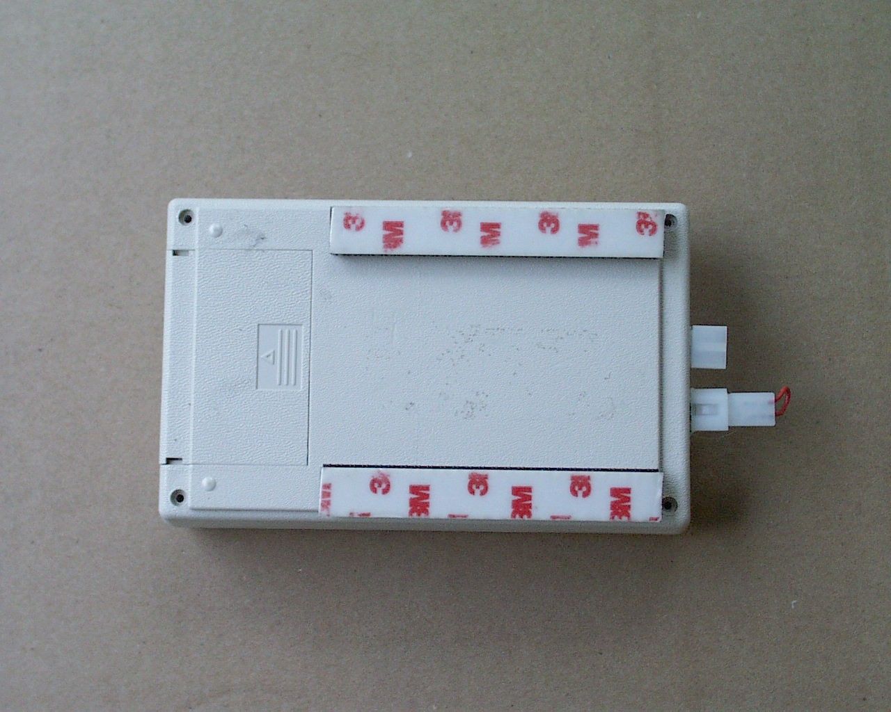
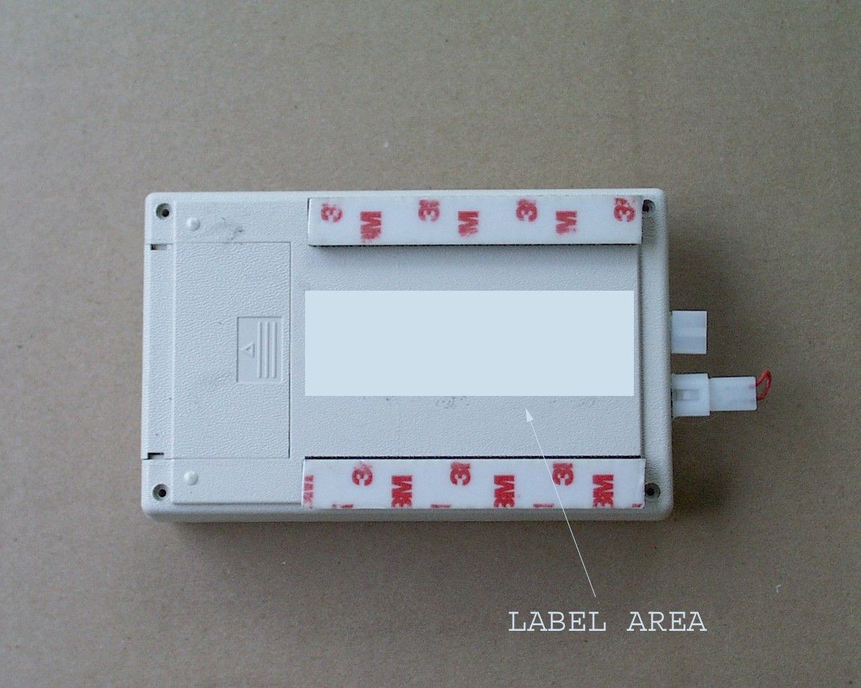
- ICEMAKERS TRANSMITTER
- Frequency Range
- 417.70000000 - 418.30000000
- Company
- ICEM Enterprises, Inc.
- Country
- United States
Documents & Files
Document Text
Text extracted from the exhibit documents filed with the FCC. Open a document above to read the original.
Users Manual
Page 1 of 4 Operating Instructions Turn on power switch located on the left side of the control box and set the time. The time must be set for the unit to work. Press and hold the Time button (leftmost button under message display) and then press the Hour or Minute buttons until the correct time appears. The display should now show the time and state “Ready / Put hose in tank.” This indicates that you are in the immediate fill mode and are ready to start filling. There are two modes of using the control: immediate fill and time delay fill. Time delay fill allows you to set a time at which filling will take place. Immediate fill This is the most commonly used mode. •Insert the hot water filling hose into the resurfacing machine’s filling hot water conduit . •Press the large red Start/Stop button. The red fill light should come on. •The display will change to a running fill time in minutes and seconds. •When the tank is filled, solenoid will stop water flow, the fill light will turn green, the unit will start to beep (1/4 second once a minute), and the display will state “Filled Remove Hose & Reset”. The fill time will be displayed until the alarm reset button is pressed. •Remove hose •Hit the Alarm Reset button •The fill light will go off and the last fill time will be displayed If you want to stop the fill cycle before it has completed, push the Start/Stop button to interrupt the fill. Page 2 of 4 Time Delay (Auto fill) fill This mode is used to set the unit to automatically fill at a preset time. Allow sufficient time for the unit to fill, e.g. program an 11:15 am fill time for an 11:30 am ice cut. •Insert the hot water filling hose into the resurfacing machine’s filling hot water conduit . •Press the Fill button (second button from the left under the display panel). The last programmed fill time will be displayed. If this is the time you wish to use, skip the next step. •To set the fill time, press and hold the Fill button while using the hour and minute buttons to set the desired time. •Press the Delay Fill button to the left of the display. •The display will show the current time, and indicate that it is in autofill mode and the start time for filling. •If the time is incorrect or to cancel the delay fill press the Delay Fill button again. The unit will now be back in immediate fill mode. •One minute before filling will commence, a 4 second alarm will sound to warn anyone present that the filling cycle is about to start. The display will read “Filling starts in 60 seconds” and will count down. This will alternate with a display reading “Push Start/Stop to Cancel”. Please double check that the hose is in place. •The fill status light will turn red when filling commences. •The rest of the cycle is identical to the immediate fill mode. Setting the Safety Timer The system has a back up time which will shut off filling after a preset amount of time. This would prevent a continuous loss of hot water if someone failed to place the hose into the tank or the resurfacer transmitter unit failed to send a filled signal due to a dead battery in the transmitter unit. The control unit comes from the factory pre programmed for 25 minutes. If the fill cycle exceeds the safety time limit, the filling will cease and the Safety time light will start flashing. The display will read “Warning Safety time > Shut off” alternating with a second message. “Remove Hose - Push Reset”. Hit the reset button before attempting to do another fill. The red safety time light will continue to flash until you have completed a successful fill. Based on your average fill times, you may wish to set a higher or lower time. (e.g. if your average fill time is 14 minutes, we recommend that you set the safety time to 16 or 17 minutes. To set the time, remove the plastic plug labeled Time Limit. Use a small screwdriver to turn the adjustment up or down from 5 to 59 minutes. As you are adjusting it, the display will show the programmed safety time. If the safety timer has stopped the fill and the replace transmitter battery light is on (non blinking), it means that the transmitter signal has stopped due to a dead battery. Replace the 9 volt transmitter battery immediately . Page 3 of 4 Power Failure When there is a power failure, the display will read “Power Down”. If the power fails during countdown (1 minute delay prior to filling), during filling, or while in delay fill mode, the lower line will read what activity was in progress at the time. In order to cancel the operation hit Start/Stop button for counting down or filling or hit the Delay Fill button if you wish to cancel the delay fill that has not started. If you do not cancel the current operation, when the power is restored that operation will continue. Fill Valve Bypass If the solenoid fails, you can still use it as a manual valve. Release the locking clip on the solenoid by lifting up on it. Unscrew the solenoid by turning it one half turn only, in a counter clockwise direction. This will allow water to flow. You can use the knob to regulate the flow or shut off flow. If the power fails during a fill and you manually fill the resurfacer until it overflows, the control unit will be in the ready to fill condition when the power is restored. Batteries The system has 2 batteries an alkaline 9V battery (Eveready # 522 or equivalent) in the transmitter and a 9 volt NiMH or NiCd rechargeable battery for the control system. The 9V nicad battery is always being recharged by the control unit circuitry The control panel has a warning light, which indicates when each has to be replaced. When the transmitter battery lamp starts to blink you have about 30 days in which to replace it. If the transmitter battery light stays on continuously, then the battery is dead (safety timer light will start blinking too, when it does not receive a filled signal) or the battery will fail in a short period of time. Page 4 of 4 Troubleshooting Inside the control unit and the transmitter unit are rese…
Text truncated - open the document above for the full version.
Block Diagram
9V BATTERY 5VSW SOURCE 5V SWITCH REGULATOR LED INDICATOR 5V 3.3V REGULATOR 3.3V SOURCE MICRO CONTROLLER BATTERY VOLTAGE MEASUREMENT CIRCUIT 418 MHZ TRANSMITTER ANTENNA 3V 200 KHZ RESONATOR 5V REGULATOR 5V SOURCE U.S. PATENT 5,762,118 CANADIAN PATENT 2,233,645 I C E M ENTERPRISES INC. DRAWING DATE 6-7-04 MODEL FIL-T-3C TRANSMITTER UNIT RED COMPONENTS ARE EXTERNAL PARTS 5VSW PRESSURE SENSOR AMPLIFEIR CIRCUITRY 5VSW OPTIONAL WATER PRESSURE SENSOR LOW VOLTAGE DROPOUT SW. 5V 5VSW TEMPERATURE SENSOR AMPLIFIER CIRCUITRY 5VSW OPTIONAL WATER TANK TEMERATURE SENSOR 5V WATER OVERFLOW SENSOR WATER OVERFLOW SENSOR CIRCUITRY 11 23 4 9 8 6 1 7 5 PRESSURE SENSOR A/D REFERENCE SOURCE CIRCUITRY 13 10 11 12
Operational Description
Page 1 FIL-T-3C CIRCUIT DESCRIPTION The FIL-T-3C transmitter unit is part of the I C E M Enterprises, Inc. Aquamatic Filling system for automatic filling of mobile vehicles. It sends information by digital coded radio frequency at 418 MHZ from the mobile vehicle to a receiver control unit. Below is a description list of the circuits & parts that make up the FIL-T-3C transmitter unit: 1) MICRO CONTROLLER (S1) This computer controls the sampling of all sensor circuits and the battery voltage. It then digital codes this information for transmitting. The computer also controls the blinking of an LED indicator. The computer codes this information into 4 word 10 bit packets (1 start bit, 8 bits data, 1 stop bit). Each bit has a duration of 400 usec . The first 2 words represents a unique serial number for identifying the unit. The next word identifies the information. The last word is data if data is available for that particular packet. The computer samples all sensors every second. It then determines if any of these samples should be digital coded and sent to the controller receiver. The battery voltage is sampled every 10 minutes and transmitted. Temperature & pressure is sent every 5 minutes if these optional sensors exist. If either of these sensors do exist & the temperature or pressure changes by a determined amount, then this information is transmitted right away. 2) 3.3 VOLT REGULATOR (S14, C1A) Supplies 3.3v to 418MHZ transmitter chip 3) 5 VOLT REGULATOR (S3, C1B) Supplies 5.0 v to the micro controller, LED indicator & water sensor circuit 4) 5 VOLT SWITCH REGULATOR (S2, C2A) This regulator is switched on & off by the micro controller, when measurements are made. It supplies 5 v to the pressure sensor circuitry & temperature sensor circuitry. 5) 418MHZ TRANSMITTER (S4, C3A, C3B, I1, I2, L1, R2A) This transmitter transmits 00k digital signal to the controller receiver. One bits are sent as RF transmission. Zero’s bits are sent as no RF transmission. During no packet transmission, the transmitter is put in sleep mode by the micro controller to save battery power. 6) 200 KHZ RESONATOR (RES, C3C, C3D) Supplies the clock frequency to run the micro controller. 7) LOW VOLTAGE DROPOUT SWITCH (S6, R1E) If the 5 volt supply drops below 4.5 volts it stops the micro controller from running Page 2 8) LED INDICATOR (D2, R9A) Blinks 4 times when a fresh battery is installed to show that the transmitter unit is running properly . It also blinks 2 times, when the water sensor is tripped to show a full water tank condition. 9) 9V BATTERY& CIRCUITRY (9V, C1C, D3) Replaceable alkaline battery supplies power to run the transmitter for about 6 months. 10) WATER OVERFLOW SENSOR CIRCUITRY (R9, R6B, C2B, L3, L4, M2F) Supplies bias current & conditions the signal of the water tank overflow sensor. When an overflow condition exists, this information is transmitted by the micro controller. 11) BATTERY VOLTAGE MEASUREMENT CIRCUITRY (R1A, R1B, R1C, R1D, T1, T2) This circuit is switched on to measure battery voltage condition by the micro controller for radio transmission of this information . 12) PRESSURE SENSOR AMPLIFIER CIRCUITRY (S5A, PS1, R1G, R1H, R1J, R10A, R10B) Differential amplifier amplifies the optional pressure sensor signal & then supples this voltage signal to an A/D input of the micro controller for measurement. 13) PRESSURE SENSOR A/D ADJ. VOLTAGE REFERENCE SOURCE(P1, R2B, R3) Calibration reference source for measuring the pressure sensor amplifier output by the micro controller A/D circuitry. 14) TEMPERATURE SENSOR AMPLIFIER CIRCUITRY(S5B, L2, L5, L6, M4F, P2 R4, R5, R7, R8) Amplifies the signal from the optional temperature water sensor & supplies this voltage signal to an A/D input of the micro controller for measurement. It also has a offset temperature adjustment for calibration purposes. I C E M ENTERPRISES INC. D. B. A. ICE MAKERS CO. 10 BUTTERMILK FALLS ROAD FORT ANN, NEW YORK 12827 518 761-3063
Schematics
- + R1H R10B OPTIONAL PRESSURE SENSOR 5VSW R10A 5VSW R1J 1/2 S5A - + 2/2 S5A PS1 5VSW R1G TP1 2.5V SW TP8 - + - + 2 3 4 1 8 5 6 7 5VSW R8 P2 R7 5VSW 2/2 1/2 TP3 .5V R5 R4 S5B S5B 9V BATTERY D3 5VSW SOURCE 5V SWITCH REGULATOR L5 C2A C3C C3D RES 200KHZ 5V R9A D2 C1C 5V S6 L3 TO WATER SENSOR RECEP. 5V SOURCE C2B R6B R9 TP8 5V REG S3 C1B 3.3V REG S14 C1 LOW V DROPOUT SW. C3A C3B R2A S4 418 MHZ TRANSMITTER L1 ANTENNA I2 I1 R1A R1B R1C R1D MICRO CONTROLLER S1 L2 TO TEMP. SENSOR RECP. 5VSW P1 R3 R2B TP2 4V 2 1 L3 L4 WATER TANK OVERFLOW SENSOR 2 4 3 1 L2 L6 L5 OPTIONAL WATER TANK TEMPERATURE SENSOR I C E M ENTERPRISES INC. DRAWING DATE 4-16-04 MODEL FIL-T-3C TRANSMITTER UNIT RED COMPONENTS ARE EXTERNAL PARTS L4 L6 TP9 T1 T2 TP4 U.S. PATENT 5,762,118 CANADIAN PATENT 2,233,645 TP6 TP7 TP5 5 7 6 8 2 3 1 4 3 1 2 3 2 1 3 2 1 M4F M2F 5V R1E 1 FIL-ST-3C PARTS LIST BATTERY REPLACEABLE 9V ALKALINE1 C1(A-C)4.7 UF SMD TANTALUM CAPACITOR2 C2(A-B)1.0 UF SMD TANTALUM CAPACITOR3 C3(A-D)330 PF SMD CERAMIC CHIP CAPACITOR4 D2T 1-3/4 RED LED5 I1SHUNT INDUCTOR .39UH (ANTI STATIC)6 I256NH INDUCTOR ANTENNA MATCHING7 L122 GA. YEL/WHI TEFLON WIRE 4.2 “ (ANTENNA)8 L222 GA. BLK TEFLON WIRE 1.7" 9 L322 GA. ORG TEFLON WIRE 3.3"10 L422 GA. BLU/WHI TEFLON WIRE 2.8"11 L522 GA. RED TEFLON WIRE 3.7"12 L622 GA. BLU/WHI TEFLON WIRE 3.7"13 M4F4 PIN .063 MOLEX FEMALE RECEPTACLE14 M2F2 PIN .063 MOLEX FEMALE RECEPTACLE15 P1POT 500 OHM 4MM CERMET SMD16 P2POT 2K OHM 4MM CERMET SMD17 PS18 PIN SMD SOCKET( OPTIONAL WATER LEVEL PRESSURE. SENSOR )18 RES200KHZ CERAMIC RESONATOR19 R1(A-H, K)RESISTOR 10K OHM 1/4 W 1%20 R2(A-B)RESISTOR 7.68K OHM 1/4 W 1%21 R3RESISTOR 1.78K OHM 1/4 W 1%22 R4RESISTOR 30K OHM 1/10 W .1%23 R5RESISTOR 10K OHM 1/10 W .1%24 R6(A-B)RESISTOR 680 OHM 1/4 W 1%25 R7RESISTOR 4.02K OHM 1/4 W 1%26 2 FIL-T-3C PARTS LIST R8RESISTOR 44.2K OHM 1/4 W 1%26 R9RESISTOR 1M OHM 1/4 W 1%27 R10(A-B)RESISTOR 100K OHM 1/4 W 1%28 S120 PIN SMD SOCKET PLUS 16C71 MICROCHIP CONTROLLER29 S25V SWITCH LDO REGULATOR SMD30 S35V LDO REGULATOR SMD31 S4TX 5002 TRANSMITTER RFM SMD32 S5(A-B)OP AMP DUAL CMOS SMD33 S6MICRO CONTROLLER SUPERVISOR N CHANNEL OPEN DRAIN SMD34 T1`PNP TRANSISTOR SMD35 T2NPN TRANSISTOR SMD36 PAC-TECH ENCLOSURE 3.4" X 5.6"37 LED LENSE38 PRESSURE SENSOR HOLE PLUG39 I C E M ENTERPRISES INC. D. B. A. ICE MAKERS CO. 10 BUTTERMILK FALLS ROAD FORT ANN, NEW YORK 12827 518 761-3063
Test Report
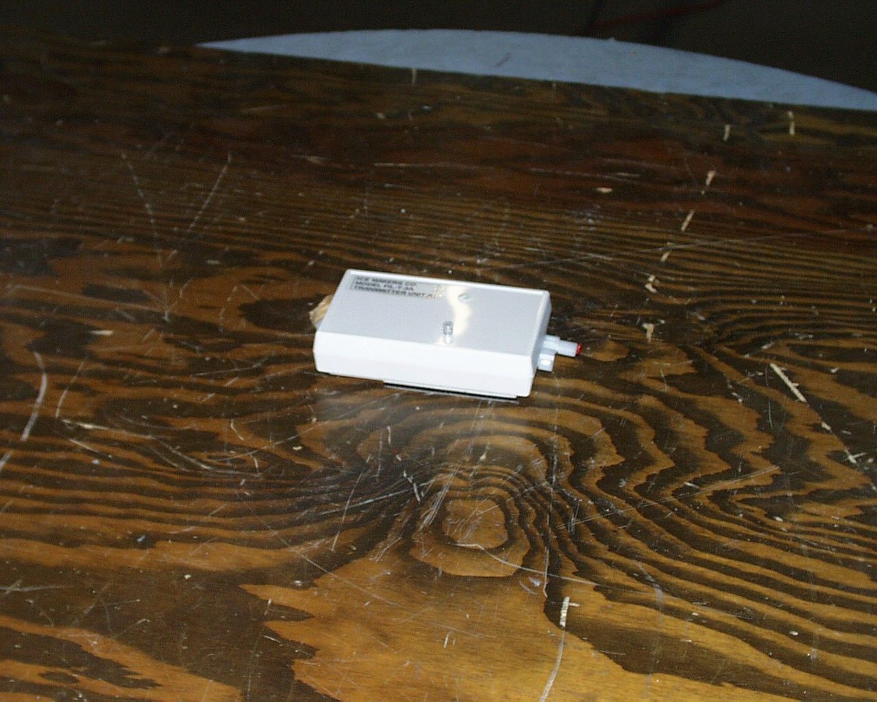
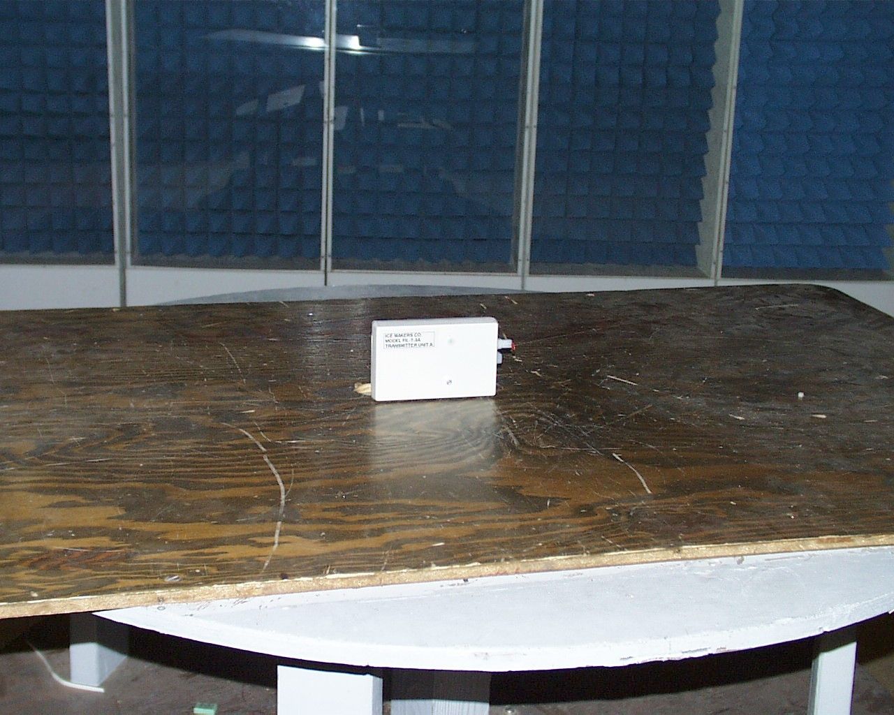
SB8-ICEM-FIL-T-3C ICEM Enterprises, Inc. 1 Test Report of an Intentional Radiator for Certification under Part 15.231(e) of the FCC rules DUT: Remote Control Transmitter FCC ID SB8-ICEM-FIL-T-3C Test Date: 07-July-2004 Manufacturer: ICEM Enterprises, Inc. 10 Buttermilk Falls Road Fort Ann, NY 12827 (518) 761-3063 Prepared by: Control Design & Testing, Inc. 6010 Red Fox Drive Spotsylvania, VA 22553 (540) 582-2826 SB8-ICEM-FIL-T-3C ICEM Enterprises, Inc. 2 A. DEVICE UNDER TEST The device is a transmitter used to control water filling systems for vehicles, in particular vehicles used for resurfacing ice rinks. The transmitter is manufactured by ICEM Enterprises, Inc and marketed under the trade name Icemakers. The frequency of operation is 418.00 MHz., nominal. The modulation mode is on/off keying using pulse code modulation. This product is designed to operate under the provisions of Part 15.231(e) of the FCC rules and RSS-210 in Canada. The test sample was supplied in the final production plastic enclosure. The device is powered by an internal 9 volt alkaline battery. The transmitter circuit is comprised of an RF Monolithics, TX-5002 transmitter hybrid IC, a two element inductive match and a 5 inch insulated wire antenna. The antenna is hard soldered to the circuit board. There is no provision to connect an external antenna. B. FACILITY: Radiated emissions testing of this device was conducted at the Carl T. Jones test facility located in Springfield, Virginia. FCC Site #90490; IC Site #3101. C. MEASUREMENT PROCEDURE: RADIATED EMISSIONS The field strength measurements were conducted according to the procedures set forth in ANSI C63.4 (1992). The device under test was placed on a rotating turntable 0.8 meters high, centered at 3 meters distant from the measurement antenna. The device was placed in the center of the turntable and tested in two positions as shown in the test setup photographs In normal operation, this device is programmed to transmit whenever an activated sensor is detected; one transmission per second maximum). For the purpose of radiated emissions testing, the test sample was specially programmed with a test routine that began continuously transmitting its code sequence on power-up. The occupied bandwidth (Plot 1) was also captured using this signal. SB8-ICEM-FIL-T-3C ICEM Enterprises, Inc. 3 Plot 1 SB8-ICEM-FIL-T-3C ICEM Enterprises, Inc. 4 The field strength measurements were taken using an HP-8596E spectrum analyzer, an EMCO 3121C dipole set, an EMCO 3115 double ridge guide horn and an Avantek UJ210 preamp. The device was scanned from 30 MHz. to 5 GHz. and all emissions were noted. In this case, the only emissions detected were the primary frequency of operation and those frequencies harmonically related to the fundamental transmit frequency. At each detected emission frequency, the device was measured by rotating the turntable and adjusting the antenna height over a range of 1 to 4 meters to obtain the maximum output level. This procedure was performed with both horizontal and vertical antenna polarizations for both of the positions shown in the test setup photos. The peak reading for each frequency was recorded in the fourth column in Table 1 below. Measurements taken for weak emissions were performed by reducing the distance from the measurement antenna to 1 meter and factoring –9.54dB into the calculation. This method was used for the 7 th and 8 th harmonics. CLIENT: ICEMAKERSFCC ID: DUT: CONTROL TRANSMITTER PART 15.231(e)DATE: 07-JULY-04 Ant. Polar. H/V 418.070H22.7-46.0215.91527624494133 836.140H30.2-85.3815.939063413 1254.210H27.6-92.3615.912921413 1672.280V29.3-96.4115.99916413 2090.350V31.0-99.8915.98013413 2508.420V32.2-102.3815.96911413 2926.490H33.6-108.0515.9427413 3344.560V34.9-113.2915.9274413 Table 1 RADIATED EMISSIONS DATA Frequency In MHz. Peak Power uV/m@3m Peak reading dBm Ant. Factor dB ANTENNA: DIPOLES/DRG HORN Duty Cycle -dB FCC Limit uV/m@3m Corrected Power uV/m@3m SB8-ICEM-FIL-T-3C ICEM Enterprises, Inc. 5 D. DUTY CYCLE AND INTERVAL CALCULATIONS The occupied bandwidth and duty cycle measurements were made using an HP-8594E spectrum analyzer and plotted with an HP-7475A pen plotter. The computation for the duty cycle correction factor for column five in Table 1 is derived from the manufacture’s description of the data scheme and is verified by plots 2 through 5 below. The data format for this device is a modified Manchester phase pulse modulation scheme. The code scheme consists of four packets transmitted as a continuous pulse stream without any spaces between the packets. Each packet is transmitted only one time for any given activation (sensor, low battery, integrity) at intervals of 1 second or longer. There can never be more than one packet in any 100ms. period. The device does not transmit a control signal every second automatically. The control transmissions are only sent in response to a request from a sensor or, in the event of low battery detection. Transmissions are sent once every 5 minutes for temperature readings once every 10 minutes for battery status (integrity). Each transmission is 16ms. long consisting of forty, 400μs. bit frames divided into four 10 bit packets. The start bits, stop bits and 1’s are represented by an “on” signal; zero’s are represented by an “off” or no transmission period. In actual operation it not possible to have all bits transmitted as 1’s. However, the calculation below is based on a transmission of all 1’s. 1 Packet 10 bits X 400μs. = 04ms. Transmission time 4 packets X 4ms = 16ms. On time per 100ms. 16ms. 20log(16ms. total on time)/100ms.) = -15.917 dB. As provided in Part 15.35 of the FCC rules, a correction factor of –15.9 dB is used for the calculations on the data sheet. The duty cycle corrected levels appear in the 7 th column in the table above. SB8-ICEM-FIL-T-3C ICEM Enterprises, Inc. 6 Plot 2 SB8-ICEM-FIL-T-3C ICEM Enterprises, Inc. 7 Plot 3 SB8-ICEM-FIL-T-3C ICEM Enterprises, Inc. 8 Plot 4 SB8…
Text truncated - open the document above for the full version.
Contact Information
Applicant
Roger Epworth(President)
Test Firm
Carl T. Jones CorporationCarl Jones
Technical Specifications
| # | Rule Parts | Frequency Range | Power Output |
|---|---|---|---|
| 1 | 15.231 | 417.7 MHz - 418.3 MHz | - |