SBYCYD0012.4GHz USB Dongle
Evermore Systems, Inc.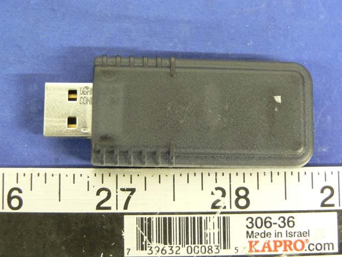
Click to zoom
Application Details
- Equipment Class
- DTS - Digital Transmission System
- Date of Grant
- Sep 06, 2005
- Application Purpose
- Original Equipment
- Date of Application
- Sep 06, 2005
- Equipment Note
- 2.4GHz USB Dongle
- Frequency Range
- 2402.00000000 - 2479.00000000
- Company
- Evermore Systems, Inc.
- Country
- United States
Documents & Files
Document Text
Text extracted from the exhibit documents filed with the FCC. Open a document above to read the original.
Users Manual
8140 N. Mopac Fwy Building 1, Suite 135. Austin, Tx 78759 HID Dongle Users Manual 17-Aug-05 1 of 3 HID Dongle Users Manual The Evermore Innovations HID dongle is a simple and elegant method for connecting wireless HID devices to a PC via Cypress Semiconductor’s Wireless USB standard. The HID Dongle is typically paired with an OEM’s HID device, such as a wireless keyboard. Binding To use the HID Dongle, the user must first “bind” the dongle to the HID device (keyboard). This is typically done at the factory before shipment of the keyboard/dongle. However, the end user may also bind the device to a keyboard by pressing the “bind” button on the dongle, and on the keyboard. The dongle’s bind button is internal to the dongle and must be pressed by inserting a paperclip or a small stiff wire into the bind button hole and depressing the button. 8140 N. Mopac Fwy Building 1, Suite 135. Austin, Tx 78759 HID Dongle Users Manual 17-Aug-05 2 of 3 LEDs The HID Dongle has 2 LEDs, one red and one green, that indicate the operational states of the device. The red LED is used for binding and the green LED indicates data transfer from the HID device to the dongle. FCC Compliance Notification CAUTION – Modifications to this device not expressly approved by Evermore Innovations could void user's authority to operate it. This device complies with Part 15 of the FCC Rules. Operation is subject to the following two conditions: (1) this device may not cause harmful interference and (2) this device must accept any interference received, including interference that may cause undesired operation. Note: This equipment has been tested and found to comply with the limits for a Class B digital device, pursuant to part 15 of the FCC Rules. These limits are designed to provide reasonable protection against harmful interference in a residential installation. This equipment generates, uses and can radiate radio frequency energy and, if not installed and used in accordance with the instructions, may cause harmful interference to radio communications. However, there is no guarantee that interference will not occur in a particular installation. If this equipment does cause harmful interference to radio or television reception, which can be determined by turning the equipment off and on, the user is encouraged to try to correct the interference by one or more of the following measures: • Reorient or relocate the receiving antenna. • Increase the separation between the equipment and receiver. • Connect the equipment into an outlet on a circuit different from that to which the receiver is connected. • Consult the dealer or an experienced radio/TV technician for help. 8140 N. Mopac Fwy Building 1, Suite 135. Austin, Tx 78759 HID Dongle Users Manual 17-Aug-05 3 of 3 IC Statement The term "IC:" before the certification /registration number only signifies that the Industry Canada technical specifications were met.
External Photos
EXHIBIT C - EUT EXTERNAL PHOTOGRAPHS EUT – Front View EUT – Back View
ID Label/Location Info
EXHIBIT A - FCC ID LABEL INFORMATION Proposed FCC ID Label Proposed Label Location on EUT Back View of EUT/FCC ID Label FCC ID: SBYCYD001 This device complies with Part 15 o the FCC Rules. Operation is subject to the following two conditions: (1) this device may not cause harmful interference, and (2) this device must accept any interference received, including interference that may cause undesired operation. 2.1875" 1.0"
Internal Photos
EXHIBIT C - EUT INERNAL PHOTOGRAPHS EUT – Component View EUT – Solder View
Test Report
Note: The test report is specially limited to the above company and this particular sample only. It may not be duplicated without prior written consent of Bay Area Compliance Laboratory Corporation. This report must not be used by the client to claim product certification, approval, or endorsement by NVLAP, NIST or any agency of the US Government. FCC PART 15.247 EMI MEASUREMENT AND TEST REPORT For Evermore Systems, Inc. 8140 North Mopac Building 1, Suite 135 Texas 78759 FCC ID: SBYCYD001 This Report Concerns: Original Report Equipment Type: 2.4GHz USB Dongle Test Engineer: Snell Leong Report No.: R0508161 Report Date: 2005-08-18 Reviewed By: Daniel Deng Prepared By: Bay Area Compliance Laboratory Corporation (BACL) 230 Commercial Street Sunnyvale, CA 94085 Tel: (408) 732-9162 Fax: (408) 732 9164 Evermore Systems, Inc. FCC ID: SBYCYD001 Report # R0508161Rpt Page 2 of 32 FCC Part 15.247 Test Report TABLE OF CONTENTS GENERAL INFORMATION.......................................................................................................................................4 PRODUCT DESCRIPTION FOR EQUIPMENT UNDER TEST (EUT) ....................................................................................4 OBJECTIVE...................................................................................................................................................................4 RELATED SUBMITTAL(S)/GRANT(S).............................................................................................................................4 TEST METHODOLOGY..................................................................................................................................................4 TEST FACILITY.............................................................................................................................................................4 SYSTEM TEST CONFIGURATION ..........................................................................................................................6 JUSTIFICATION.............................................................................................................................................................6 EUT EXERCISE SOFTWARE..........................................................................................................................................6 SPECIAL ACCESSORIES.................................................................................................................................................6 SCHEMATICS / BLOCK DIAGRAM.................................................................................................................................6 EQUIPMENT MODIFICATIONS.......................................................................................................................................6 LOCAL SUPPORT EQUIPMENT LIST AND DETAILS........................................................................................................6 CONFIGURATION OF TEST SYSTEM..............................................................................................................................7 TEST SETUP BLOCK DIAGRAM.....................................................................................................................................7 SUMMARY OF TEST RESULTS ...............................................................................................................................8 §15.203 - ANTENNA REQUIREMENT......................................................................................................................9 STANDARD APPLICABLE..............................................................................................................................................9 §15.207(A) - CONDUCTED EMISSIONS.................................................................................................................10 MEASUREMENT UNCERTAINTY..................................................................................................................................10 EUT SETUP................................................................................................................................................................10 SPECTRUM ANALYZER SETUP....................................................................................................................................10 TEST EQUIPMENT LIST AND DETAILS.........................................................................................................................10 TEST PROCEDURE......................................................................................................................................................10 SUMMARY OF TEST RESULTS.....................................................................................................................................11 CONDUCTED EMISSIONS TEST DATA.........................................................................................................................11 PLOT OF CONDUCTED EMISSIONS TEST DATA...........................................................................................................11 §2.1051, §15.205, §15.209, §15.247 (C) - SPURIOUS EMISSIONS AT ANTENNA TERMINALS ....................14 STANDARD APPLICABLE............................................................................................................................................14 MEASUREMENT PROCEDURE......................................................................................................................................14 EQUIPMENT LISTS......................................................................................................................................................14 MEASUREMENT RESULT............................................................................................................................................14 §15.205 & §15.209 - SPURIOUS RADIATED EMISSION......…
Text truncated - open the document above for the full version.
Test Setup Photos
EXHIBIT B - TEST SETUP PHOTOGRAPHS Conducted Emission - Front View Conducted Emission - Side View Radiated Emission - Front View Radiated Emission - Rear View
Contact Information
Applicant
John H Lupher(President)
Test Firm
Bay Area Compliance LaboratoryJohn Chan
Technical Specifications
| # | Rule Parts | Frequency Range | Power Output |
|---|---|---|---|
| 1 | 15C | 2.40 GHz - 2.48 GHz | 490.00 µW |
Other Applications from Evermore Systems, Inc.
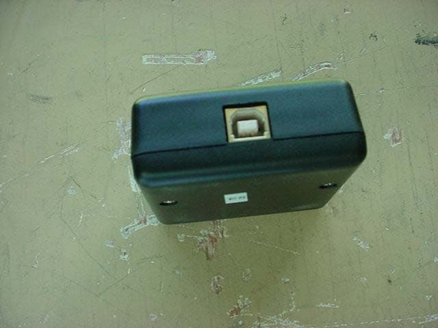
SBYSSL1
Jul 26, 2004Smart Swing USB Link Box
Equipment Class
DXX - Part 15 Low Power Communication Device Transmitter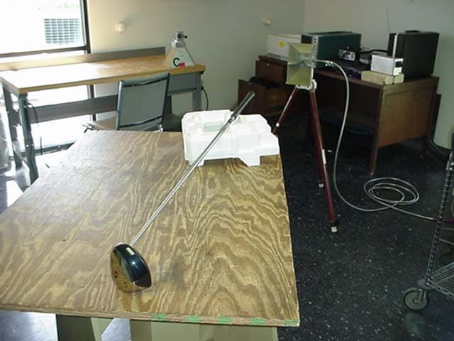
SBYSSC1
Jul 26, 2004Smart Swing Golf Club
Equipment Class
DXX - Part 15 Low Power Communication Device Transmitter