SC6VLS410S241FHSS Transmitter
Voxware, Inc.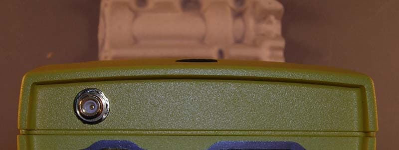
Click to zoom
Application Details
- Equipment Class
- DSS - Part 15 Spread Spectrum Transmitter
- Date of Grant
- Oct 14, 2004
- Application Purpose
- Original Equipment
- Date of Application
- Oct 14, 2004
- Equipment Note
- FHSS Transmitter
- Frequency Range
- 2402.00000000 - 2480.00000000
- Company
- Voxware, Inc.
- Country
- United States
Documents & Files
Document Text
Text extracted from the exhibit documents filed with the FCC. Open a document above to read the original.
Users Manual
VLS-410 Technical Specifications Processor PXA255, 400 Mhz OS WinCE.NET Runtime Memory (SDRAM) 128Mbyte Storage Memory (Flash) 64Mbyte Battery Life >10 hrs Hardware Interface Ports 2 serial, USB Client Weight 22 ounces with battery Batch Mode (buffered results) Yes Radio Support WIFI 802.11b; Symbol 802.11 TTS (Text-to- Speech) Engine Cepstral, higher quality male voice Internal Card Support PCMCIA/CF,SD Power LED Status Green light will blink slowly (once every 3 seconds ) during a software upgrade Green light will blink normal (once a second) once the browser is started. Green light will remain solid for 30 seconds or so when unit is booted up. Red light will blink fast if the unit has an error during the system install. No lights are normal when the unit runs out of battery or suspends. Alternate Red and Green blinking lights (once a second) is normal when the unit is out of range. Battery Change Procedures 1. Press & release the SUSPEND/RESUME button. 2. WAIT for the power light to go out (approximately 1.5 seconds). 3. Press the battery release button and lift out the battery pack. 4. Take a fully charged battery pack from the battery charger. 5. Press down firmly on the battery pack until you hear a small click. NOTE: After suspending the device and removing the battery, if a new battery is not inserted within 7 minutes then the unit will RESET when the battery is inserted. Caution! Changes and modifications not expressly approved by Voxware, Inc. could void the user’s authority to operate the equipment. This product must be professionally installed. Approved Accessories The accessories listed below are approved for use with the VLS-410 and the use of any other accessories is prohibited. Metrologic Bar Code Scanner Model # IS 4220 Available with Voxware compatible cable from Accucode +1-303-639-6111 VLS Pouch Available from Voxware VLS Headset Available from Voxware Battery Pack Suspend/ Resume button Reset button Battery Release button Suspending the Unit To SUSPEND the unit do the following: 1. Press & release the SUSPEND/RESUME button. The power light will go out in 1.5 seconds. Warning! Holding down the SUSPEND/RESUME button for more than 8 seconds will RESET the VLS–410 device. To RESUME the unit (after suspending it) just press & release the SUSPEND/RESUME button again. Notes: The VLS-410 unit will automatically go into Suspend mode when the battery charge is below 5%. In this instance, the battery will remain in Suspend mode for up to 2 days, if not removed sooner. VLS-410 Software Update Messages On occasion your device will need to be updated with new software/files. When this occurs you will hear one of the following messages: Resetting the Unit Method 1: 1. Remove the battery (while the unit is On). 2. Wait for the power light to go out. 3. Put the battery back on again. Method 2: 1. Press for more than 8 seconds the SUSPEND/RESUME button. Method 3: Cold Hardware Reset . 1. Press & release the SUSPEND/RESUME button. 2. Wait for the power light to go out. 3. Press the RESET button. A cold hardware reset of the unit is performed. Warning! Pressing the RESET button when the unit is ON may cause a loss of data . Version 7 9/29/04 Voxware VoiceLogistics ® VLS-410 Tech Specs & Usage Procedures Regulatory Information This equipment is within SAR (specific absorption rate) limits for a portable device in contact with the body. The maximum SAR measurement in Voxware’s supplied pouch is 0.091 W/kg Body. Industry Canada: This device has been designed to operate with an antenna having a maximum gain of 0 dB. An antenna having a higher gain is strictly prohibited per regulations of Industry Canada. The required antenna impedance is 50 Ohms. To reduce potential interference to other users, the antenna type and its gain should be so chosen so that the equivalent isotropically radiated power (EIRP) is not more than that required for successful communication. Message Software Type Installing new application version Application Updating Browser files Browser Updating Shell files Shell Installing new system version System Build Updating TTS files TTS
Cover Letter(s)
Response to TCB Findings 1. For the SAR testing please supply the calibration data for the E-field probe and the dipole antenna. Supplied. 2. For the SAR testing please clarify why there is no distribution overlay for configuration 3 on page 19 of the test report. There was no distribution overlay for configuration 3 on pg 19 because there was no detectable SAR level, as it stated in the table.
External Photos
REPORT: EE0056-3 FCC ID: SC6VLS410S241 EXHIBIT: External Photos MODEL: VLS-410 _____________________________________________________________ _____________________________________________________________ Curtis-Straus LLC • 527 Great Road • Littleton, MA • TEL (978) 486-8880 • FAX (978) 486-8828 Page 1 of 3 REPORT: EE0056-3 FCC ID: SC6VLS410S241 EXHIBIT: External Photos MODEL: VLS-410 _____________________________________________________________ _____________________________________________________________ Curtis-Straus LLC • 527 Great Road • Littleton, MA • TEL (978) 486-8880 • FAX (978) 486-8828 Page 2 of 3 REPORT: EE0056-3 FCC ID: SC6VLS410S241 EXHIBIT: External Photos MODEL: VLS-410 _____________________________________________________________ _____________________________________________________________ Curtis-Straus LLC • 527 Great Road • Littleton, MA • TEL (978) 486-8880 • FAX (978) 486-8828 Page 3 of 3
External Photos
REPORT: EE0056-3 FCC ID: SC6VLS410S241 EXHIBIT: External Photos MODEL: VLS-410 _____________________________________________________________ _____________________________________________________________ Curtis-Straus LLC • 527 Great Road • Littleton, MA • TEL (978) 486-8880 • FAX (978) 486-8828 Page 1 of 4 REPORT: EE0056-3 FCC ID: SC6VLS410S241 EXHIBIT: External Photos MODEL: VLS-410 _____________________________________________________________ _____________________________________________________________ Curtis-Straus LLC • 527 Great Road • Littleton, MA • TEL (978) 486-8880 • FAX (978) 486-8828 Page 2 of 4 REPORT: EE0056-3 FCC ID: SC6VLS410S241 EXHIBIT: External Photos MODEL: VLS-410 _____________________________________________________________ _____________________________________________________________ Curtis-Straus LLC • 527 Great Road • Littleton, MA • TEL (978) 486-8880 • FAX (978) 486-8828 Page 3 of 4 REPORT: EE0056-3 FCC ID: SC6VLS410S241 EXHIBIT: External Photos MODEL: VLS-410 _____________________________________________________________ _____________________________________________________________ Curtis-Straus LLC • 527 Great Road • Littleton, MA • TEL (978) 486-8880 • FAX (978) 486-8828 Page 4 of 4
External Photos
H9PLA3021 H9PLA3021
ID Label/Location Info
REPORT: EE0056-3 FCC ID: SC6VLS410S241 EXHIBIT: Label Location MODEL: VLS-410 _____________________________________________________________ _____________________________________________________________ Curtis-Straus LLC • 527 Great Road • Littleton, MA • TEL (978) 486-8880 • FAX (978) 486-8828 Page 1 of 1 Description: 2.5 mil, soft PVC film Adhesive: Solvent polyacrylate, permanent adhesive Adhesive power(FINAT-TM 1, after 24 h, stainless steel): min. 4.6 lb/in
Internal Photos
REPORT: EE0056-3 FCC ID: SC6VLS410S241 EXHIBIT: Internal Photos MODEL: VLS-410 _____________________________________________________________ _____________________________________________________________ Curtis-Straus LLC • 527 Great Road • Littleton, MA • TEL (978) 486-8880 • FAX (978) 486-8828 Page 1 of 3 REPORT: EE0056-3 FCC ID: SC6VLS410S241 EXHIBIT: Internal Photos MODEL: VLS-410 _____________________________________________________________ _____________________________________________________________ Curtis-Straus LLC • 527 Great Road • Littleton, MA • TEL (978) 486-8880 • FAX (978) 486-8828 Page 2 of 3 REPORT: EE0056-3 FCC ID: SC6VLS410S241 EXHIBIT: Internal Photos MODEL: VLS-410 _____________________________________________________________ _____________________________________________________________ Curtis-Straus LLC • 527 Great Road • Littleton, MA • TEL (978) 486-8880 • FAX (978) 486-8828 Page 3 of 3 Note: These internal photos were taken from a previous Voxware application. The Cisco card will be replaced with the Symbol LA-3021-100- US card.
Internal Photos
H9PLA3021-100 H9PLA3021-100 H9PLA3021-100 H9PLA3021-100
RF Exposure Info
SAR EVALUATION CERTIFICATE OF COMPLIANCE APPLICANT: Voxware Inc. EUT: VLS 410 W/SYMBOL SPECTRUM24 100 Date of Receipt: August 26, 2004 Device Category: WLAN RF exposure environment: Uncontrolled RF exposure category: Portable Power supply: Powered by Battery Antenna: Integrated Antenna Production/prototype: Identical Prototype Measured Standards: FCC OET 65 SUPPLEMENT C Modulation: FHSS (GFSK ) Crest Factor: FHSS = 1 TX Range: 2402 – 2480 MHz RX Range: 2412 – 2480 MHz Used TX Channels: Low: ch 2402 MHz Center: ch 2440 MHz High: ch. 2480 MHz Maximum RF Power Output: 0.045 Conducted RF power Maximum SAR Measurement (averaged over: 1g) 0.091 W/kg Body Kevin Mehaffey EMC Lab Manager APPLICANT NAME AND ADDRESS: DATE OF TEST: August 26, 2004 Voxware Inc.. TEST LOCATION: MET LABORATORIES INC. 185 Alewife brook parkway 914 West Patapsco Ave. Cambridge, MA 02138 Baltimore, Maryland 21230 This wireless portable device has been tested in accordance with the measurement procedures specified in FCC OET 65 SUPPLEMENT C and IEEE Std. 1528- (July 2001), and has been shown to be capable of compliance for localized specific absorption rate (SAR) for uncontrolled environment/general population exposure limits specified in ANSI/IEEE Std. C95.3 - 2002 I attest to the accuracy of this data. All reported measurements were performed by me, or were made under my supervision, and are correct to the best of my knowledge and belief. I assume full responsibility for the completeness of these measurements and vouch for the qualifications of all persons taking them. Voxware Inc. VLS 410 W/SYMBOL SPECTRUM24 100 (FCC ID SC6VLS410S241) September 22, 2004 EMC15834-SAR-FCC Copyright 2003, MET Laboratories, Inc. Page 2 of 45 August 26, 2004 Voxware Inc. 185 Alewife brook parkway Cambridge, MA 02138 Reference: VLS 410 W/SYMBOL SPECTRUM24 100 Dear Mr. Frederick Earthrowl : Enclosed is the EMC SAR Evaluation Report for the Voxware Inc. VLS 410 W/SYMBOL SPECTRUM24 100. It was tested in accordance with the measurement procedures specified in FCC OET 65 SUPPLEMENT C shown to be capable to be in compliance for localized specific absorption rate (SAR) for uncontrolled environment/general population exposure limits specified in FCC OET 65 SUPPLEMENT C. Thank you for using the testing services of MET Laboratories. If you have any questions regarding these results or if MET can be of further assistance to you, please feel free to contact me. We appreciate your business and look forward to working with you again soon. Kindest Regards, MET LABORATORIES, INC. Marianne T. Bosley EMC Administrator Enclosures: DOCTEM-23 Jan 04 Certificates and reports shall not be reproduced except in full, without the written permission of MET Laboratories, Inc. The Nation’s First Licensed Nationally Recognized Testing Laboratory Voxware Inc. VLS 410 W/SYMBOL SPECTRUM24 100 (FCC ID SC6VLS410S241) September 22, 2004 EMC15834-SAR-FCC Copyright 2003, MET Laboratories, Inc. Page 3 of 45 Dosimetric Assessment Test Report for the Voxware Inc. VLS 410 W/SYMBOL SPECTRUM24 100 Tested and Evaluated In Accordance With FCC OET 65 SUPPLEMENT C MET REPORT: EMC15834-SAR-FCC August 26, 2004 PREPARED FOR: Voxware Inc. 185 Alewife brook parkway Cambridge, MA 02138 PREPARED BY: MET Laboratories, Inc. 914 West Patapsco Avenue Baltimore, Maryland 21230-3432 Voxware Inc. VLS 410 W/SYMBOL SPECTRUM24 100 (FCC ID SC6VLS410S241) September 22, 2004 EMC15834-SAR-FCC Copyright 2003, MET Laboratories, Inc. Page 4 of 45 Dosimetric Assessment T EST REPORT for the Voxware Inc. VLS 410 W/SYMBOL SPECTRUM24 100 In Accordance With FCC OET 65 SUPPLEMENT C Prepared for Voxware Inc. 185 Alewife brook parkway Cambridge, MA 02138 Kevin Mehaffey EMC LAB MANAGER Report Prepared By Marianne T. Bosley EMC ADMINISTRATOR Report Reviewed By Liming Xu TEST ENGINEER Final Review By EMC LAB MANAGER Engineering Statement: The measurements shown in this report were made in accordance with the procedures specified in FCC OET 65 SUPPLEMENT C. I assume full responsibility for the accuracy and completeness of these measurements, and for the qualifications of all persons taking them. It is further stated that upon the basis of the measurements made, the equipment evaluated is capable of compliance for localized specific absorption rate (SAR) for uncontrolled environment/general population exposure limits specified in ANSI/IEEE Std. C95.3-2002. ← Voxware Inc. VLS 410 W/SYMBOL SPECTRUM24 100 (FCC ID SC6VLS410S241) September 22, 2004 EMC15834-SAR-FCC Copyright 2003, MET Laboratories, Inc. Page 5 of 45 Quick Links • Summary of test Report • EUT Description • Test Conditions • Host Laptops Used • System Validation • SAR results summary • SAR Area Scans • Setup Pictures • Measurement System ← Voxware Inc. VLS 410 W/SYMBOL SPECTRUM24 100 (FCC ID SC6VLS410S241) September 22, 2004 EMC15834-SAR-FCC Copyright 2003, MET Laboratories, Inc. Page 6 of 45 OBJECTIVE The objective of the procedure was to perform a dosimetric assessment one of the VLS 410 W/SYMBOL SPECTRUM24 100 card. The measurements have been carried out with the dosimetric assessment system “SARA2", and were made according to the FCC OET 65 SUPPLEMENT C for evaluating compliance of mobile and portable devices with FCC OET 65 SUPPLEMENT C limits for human exposure in the general population to radio frequency emissions. SAR DEFINITION Specific absorption rate (SAR) is the biological relevant parameter describing the effects of electromagnetic fields in the frequency range of interest. It is a measure of the power absorbed per unit mass and may be spatially averaged over the total mass of an exposed body or its parts. In mathematical terms Specific Absorption Rate (SAR) is defined as the time derivative (rate) of the incremental energy absorbed by (dissipated in) an incremental mass contained in a volume element of a given density. It is also defined as the rate of RF energy absorption per unit mass at a point in an absorbing body as given below. The SAR is calculat…
Text truncated - open the document above for the full version.
RF Exposure Info
IXP-050 Calibration Certificate Indexsar Limited Oakfield House Cudworth Lane Newdigate Surrey RH5 5BG Tel: +44 (0) 1306 632 870 Fax: +44 (0) 1306 631 834 e-mail: [email protected] Calibration Certificate Dosimetric E-field Probe Type: IXP-050 Manufacturer: IndexSAR, UK Serial Number: 0163 Place of Calibration: IndexSAR, UK IndexSAR Limited hereby declares that the IXP-050 Probe named above has been calibrated for conformity to the IEEE 1528 and CENELEC EN 50361 standards on the date shown below. Date of Initial Calibration: 12 th August 2004 The probe named above will require a calibration check on the date shown below. Next Calibration Date: August 2005 The calibration was carried out using the methods described in the calibration document. Where applicable, the standards used in the calibration process are traceable to the UK’s National Physical Laboratory. Calibrated By: Approved By: Please keep this certificate with the calibration document. When the probe is sent for a calibration check, please include the calibration document.
RF Exposure Info
Page 1 of 21 IMMERSIBLE SAR PROBE CALIBRATION REPORT Part Number: IXP – 050 S/N 0163 August 2004 Indexsar Limited Oakfield House Cudworth Lane Newdigate Surrey RH5 5BG Tel: +44 (0) 1306 632 870 Fax: +44 (0) 1306 631 834 e-mail: [email protected] Page 2 of 21 INTRODUCTION This Report presents measured calibration data for a particular Indexsar SAR probe (S/N 0163) and describes the procedures used for characterisation and calibration. Indexsar probes are characterised using procedures that, where applicable, follow the recommendations of CENELEC [1] and IEEE [2] standards. The procedures incorporate techniques for probe linearisation, isotropy assessment and determination of liquid factors (conversion factors). Calibrations are determined by comparing probe readings with analytical computations in canonical test geometries (waveguides) using normalised power inputs. Each step of the calibration procedure and the equipment used is described in the sections below. CALIBRATION PROCEDURE 1. Equipment Used For the first part of the characterisation procedure, the probe is placed in an isotropy measurement jig as pictured in Figure 1. In this position the probe can be rotated about its axis by a non-metallic belt driven by a stepper motor. The probe is attached via its amplifier and an optical cable to a PC. A schematic representation of the test geometry is illustrated in Figure 2. A balanced dipole (900 MHz) is inserted horizontally into the bracket attached to a second belt (Figure 1). The dipole can also be rotated about its axis. A cable connects the dipole to a signal generator, via a directional coupler and power meter. The signal generator feeds an RF amplifier at constant power, the output of which is monitored using the power meter. The probe is positioned so that its sensors line up with the rotation center of the source dipole. By recording output voltage measurements of each channel as both the probe and the dipole are rotated, data are obtained from which the spherical isotropy of the probe can be optimised and its magnitude determined. The calibration process requires E-field measurements to be taken in air, in 900 MHz simulated brain liquid and at other frequencies/liquids as appropriate. 2. Linearising probe output The probe channel output signals are linearised in the manner set out in Refs [1] and [2]. The following equation is utilized for each channel: U lin = U o/p + U o/p 2 / DCP (1) where U lin is the linearised signal, U o/p is the raw output signal in voltage units and DCP is the diode compression potential in similar voltage units. Page 3 of 21 DCP is determined from fitting equation (1) to measurements of U lin versus source feed power over the full dynamic range of the probe. The DCP is a characteristic of the schottky diodes used as the sensors. For the IXP-050 probes with CW signals the DCP values are typically 0.10V (or 20 in the voltage units used by Indexsar software, which are V*200). 3. Selecting channel sensitivity factors to optimise isotropic response The basic measurements obtained using the calibration jig (Fig 1) represent the output from each diode sensor as a function of the presentation angle of the source (probe and dipole rotation angles). The directionality of the orthogonally-arranged sensors can be checked by analysing the data using dedicated Indexsar software, which displays the data in 3D format as in Figure 3. The left-hand side of this diagram shows the individual channel outputs after linearisation (see above). The program uses these data to balance the channel outputs and then applies an optimisation process, which makes fine adjustments to the channel factors for optimum isotropic response. The next stage of the process is to calibrate the Indexsar probe to a W&G EMR300 E-field meter in air. The principal reasons for this are to obtain conversion factors applicable should the probe be used in air and to provide an overall measure of the probe sensitivity. A multiplier is applied to factors to bring the magnitudes of the average E-field measurements as close as possible to those of the W&G probe. The following equation is used (where linearised output voltages are in units of V*200): E air 2 (V/m) = U linx * Air Factor x + U liny * Air Factor y + U linz * Air Factor z (2) It should be noted that the air factors are not separately used for normal SAR testing. The IXP-050 probes are optimised for use in tissue-simulating liquids and do not behave isotropically in air. 4. 900 MHz Liquid Calibration Conversion factors for use when the probes are immersed in tissue-simulant liquids at 900 MHz are determined either using a waveguide or by comparison to a reference probe that has been calibrated by NPL. Waveguide procedures are described later. The summary sheet indicates the method used for the probe S/N 0163. The conversion factor, referred to as the ‘liquid factor’ is also applied to the measurements of each channel. The following equation is used (where output voltages are in units of V*200): E liq 2 (V/m) = U linx * Air Factor x * Liq Factor x + U liny * Air Factor y * Liq Factor y + U linz * Air Factor z * Liq Factor z (3) Page 4 of 21 A 3D representation of the spherical isotropy for probe S/N 0163 using these factors is shown in Figure 3. The rotational isotropy can also determined from the calibration jig measurements and is reported as the 900MHz isotropy in the summary table. Note that waveguide measurements can also be used to determine rotational isotropy (Fig. 5). The design of the cells used for determining probe conversion factors are waveguide cells is shown in Figure 4. The cells consist of a coax to waveguide transition and an open-ended section of waveguide containing a dielectric separator. Each waveguide cell stands in the upright position and is filled with liquid within 10 mm of the open end. The separator provides a liquid seal and is designed for a good electrical transition from air filled guide to liquid filled g…
Text truncated - open the document above for the full version.
RF Exposure Info
Company Reg No. 4075046 Reg. Office: Oakfield House, Cudworth Lane, Newdigate, Surrey RH5 5DR.. Directors: D Riley and MI Manning PhD. Indexsar Limited Oakfield House Cudworth Lane Newdigate Surrey RH5 5BG Tel: +44 (0) 1306 632 870 Fax: +44 (0) 1306 631 834 e-mail: [email protected] Calibration / Conformance statement Balanced Validation dipole Type: IXD-245 2450MHz Manufacturer: IndexSAR, UK Serial Number: 0041 Place of Calibration: IndexSAR, UK IndexSAR Limited hereby declares that the IXD series dipole named above has been checked for conformity to the specifications given in the draft IEEE 1528 and CENELEC En 50361 standards on the date shown below. Date of Calibration/Check: 11 th November 2002 The dipole named above should be periodically re-checked using the procedures set out in the dipole calibration document. It is important that the cautions regarding handling of the dipoles (given in the calibration document) are adhered to. Provided the dipole is undamaged and the periodic checks show that it continues to meet the return loss figures quoted in the calibration document, the recommended period before for re-calibration is due is 5 years. Next Calibration Date: November 2007 The calibration measurements were carried out using the methods described in the calibration document. Where applicable, the standards used in the calibration process are traceable to the UK’s National Physical Laboratory. Calibrated By: Approved By:
RF Exposure Info
These are the results from our recent functional verification of the Dipole antennas used exclusively in the validation of our SAR system. Provided below are plots provided by the manufacturer, followed by the results of our verification. 900MHZ Dipole MFR return loss Data 900 MHz validation return loss data 8/20/2004 1800MHZ Dipole MFR return loss Data 1800MHz dipole validation return loss data 8/20/2004 2450MHz dipole MFR return loss data. 2450 dipole verification return loss data 8/20/2004
Test Report
Curtis-Straus LLC is accredited by the American Association for Laboratory Accreditation for the specific scope of accreditation under Certificate Number 1627-01. This report may contain data which is not covered by the A2LA accreditation. _____________________________________________________________ Curtis-Straus LLC • 527 Great Road • Littleton, MA • TEL (978) 486-8880 • FAX (978) 486-8828 Test Report Report No EE0056-3 Client Voxware, Inc. 185 Alewife Brook Parkway Cambridge, MA 02138 Phone 617-497-0200 Fax 617-576-2123 FRN 0010250033 Model VLS-410 w/ 100mW Symbol card FCC ID SC6VLS410S241 Equipment Type Spread Spectrum Transmitter Equipment Code DSS Results As detailed within this report Prepared by _____________________ Evan Gould – Test Engineer Authorized by __________________________ Michael Buchholz – EMC Manager Issue Date Conditions of issue This Test Report is issued subject to the conditions stated in ‘terms and conditions’ section of this report. REPORT: EE0056-3 FCC ID: SC6VLS410S241 _____________________________________________________________ _____________________________________________________________ Curtis-Straus LLC • 527 Great Road • Littleton, MA • TEL (978) 486-8880 • FAX (978) 486-8828 Page 2 of 30 Table Of Contents Summary......................................................................................................................... 3 Test Methodology............................................................................................................ 3 Statement of Conformity.................................................................................................. 4 EUT Configuration........................................................................................................... 5 20dB Bandwidth.............................................................................................................. 6 Channel Separation......................................................................................................... 9 Number of Hopping Frequencies.................................................................................. 10 Time of Occupancy (Dwell Time).................................................................................. 13 Peak Output Power....................................................................................................... 15 Conducted Spurious Emissions.................................................................................... 16 Conducted Band Edges................................................................................................ 18 Radiated Band Edge..................................................................................................... 22 Radiated Spurious Emissions....................................................................................... 24 Test Equipment Used.................................................................................................... 25 Terms And Conditions................................................................................................... 26 A2LA Accreditation........................................................................................................ 28 REPORT: EE0056-3 FCC ID: SC6VLS410S241 _____________________________________________________________ _____________________________________________________________ Curtis-Straus LLC • 527 Great Road • Littleton, MA • TEL (978) 486-8880 • FAX (978) 486-8828 Page 3 of 30 Summary This test report supports an application for certification of a transmitter operating pursuant to 47 CFR 15.247. The product is the Voxware VLS-410 with the Symbol LA- 3021-100-US card. It is a frequency hopper that operates in the range 2400- 2483.5MHz. It utilizes a hopping table of 79 channels. The LA-3021-100-US card has previously been certified as FCC ID H9PLA3021-100. The purpose of this application is to certify the VLS-410 which utilizes this radio with a new antenna (Proxim 7742 0dBi omnidirectioinal antenna) in a body worn configuration. Test Methodology Radiated emissions testing is performed according to the procedures specified in ANSI C63.4 (2003). Public Notice DA 00-705 “Filing and Measurement Guidelines for Frequency Hopping Spread Spectrum Systems” was followed for testing as well. Emissions were maximized by rotating the EUT (including external antenna) around three orthogonal axes as well as varying the test antenna’s height and polarity. The external antenna can not be maximized separately. Fresh batteries were used throughout testing. Frequency range investigated: 30MHz – 26.5GHz Measurement distance: 30 - 1000MHz 3m 1 – 26.5GHz 1m REPORT: EE0056-3 FCC ID: SC6VLS410S241 _____________________________________________________________ _____________________________________________________________ Curtis-Straus LLC • 527 Great Road • Littleton, MA • TEL (978) 486-8880 • FAX (978) 486-8828 Page 4 of 30 Statement of Conformity The VLS-410 has been found to conform to the following parts of 47 CFR as detailed below: Part 2 Part 15 Comments 15.15(b) There are no controls on this device that adjust the power level. 2.925 15.19 The label is shown in the label exhibit. 15.21 Information to the user is shown in the instruction manual exhibit. 15.27 No special accessories are required for compliance. 15.203 The external antenna connector is a unique connector type: reverse MCX. 15.205 15.209 The fundamental is not in a Restricted band and the spurious and harmonic emissions in the Restricted bands comply with the general emission limits of 15.209. 15.207 The unit is battery powered. 15.247 The unit complies with the frequency hopper requirements of 15.247 REPORT: EE0056-3 FCC ID: SC6VLS410S241 _____________________________________________________________ _____________________________________________________________ Curtis-Straus LLC • 527 Great Road • Littleton, MA • TEL (978) 486-8880 • FAX (978) 486-8828 Page 5 of 30 EUT Configuration EUT Co…
Text truncated - open the document above for the full version.
Test Setup Photos
REPORT: EE0056-3 FCC ID: SC6VLS410S241 EXHIBIT: Setup Photos MODEL: VLS-410 _____________________________________________________________ _____________________________________________________________ Curtis-Straus LLC • 527 Great Road • Littleton, MA • TEL (978) 486-8880 • FAX (978) 486-8828 Page 1 of 2 Radiated Emissions Radiated Emissions REPORT: EE0056-3 FCC ID: SC6VLS410S241 EXHIBIT: Setup Photos MODEL: VLS-410 _____________________________________________________________ _____________________________________________________________ Curtis-Straus LLC • 527 Great Road • Littleton, MA • TEL (978) 486-8880 • FAX (978) 486-8828 Page 2 of 2 Antenna Port Conducted Emissions
Contact Information
Applicant
Nichole St.. Martin(Operations Manager)
Test Firm
BUREAU VERITAS CONSUMER PRODUCTS SERVICES, INC.Ozgur Ozturk
[email protected]978-486-8880
Technical Specifications
| # | Rule Parts | Frequency Range | Power Output |
|---|---|---|---|
| 1 | 15C | 2.40 GHz - 2.48 GHz | 35.00 mW |