SC7VST3Vital Signs Transmitter Model VST3
Biowatch Medical, Inc.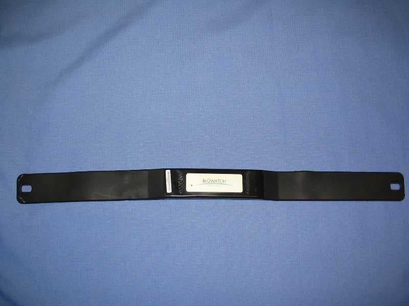
Click to zoom
Application Details
- Equipment Class
- PCT - PCS Licensed Transmitter worn on body
- Date of Grant
- Aug 26, 2004
- Application Purpose
- Original Equipment
- Date of Application
- Aug 26, 2004
- Equipment Note
- Vital Signs Transmitter Model VST3
- Frequency Range
- 824.70000000 - 848.30000000
- Company
- Biowatch Medical, Inc.
- Country
- United States
Documents & Files
Document Text
Text extracted from the exhibit documents filed with the FCC. Open a document above to read the original.
Users Manual
Personal Health Monitoring Services SM VITAL SIGNS TRANSMITTER ™ • MODEL: VST 3 TM Instruction Manual 1 TABLE OF CONTENTS Introduction . . . . . . . . . . . . . . . . . . . . . . . . . . . . . . . . . . .2 Get to Know Your Vital Signs Transmitter . . . . . . . . . . . .4 How the Vital Signs Transmitter Works . . . . . . . . . . . . .5 Clinical Monitoring Center Intervention . . . . . . . . . . . .5 Emergency Medical Service (EMS) Intervention . . . . . . .6 Event Button Intervention . . . . . . . . . . . . . . . . . . . . . . .6 Immediate Voice Response Intervention . . . . . . . . . . . . .6 Notifications . . . . . . . . . . . . . . . . . . . . . . . . . . . . . . . . .7 When to Wear Your Vital Signs Transmitter . . . . . . . . . . .8 Using the Vital Signs Transmitter for the First Time . . . .9 Getting Started . . . . . . . . . . . . . . . . . . . . . . . . . . . . . .10 Charging the Vital Signs Transmitter . . . . . . . . . . . . . .12 How to Wear Your Vital Signs Transmitter . . . . . . . . . .15 Care and Maintenance . . . . . . . . . . . . . . . . . . . . . . . . . .17 Cleaning . . . . . . . . . . . . . . . . . . . . . . . . . . . . . . . . . . .17 Troubleshooting . . . . . . . . . . . . . . . . . . . . . . . . . . . . . .18 Limited Warranty . . . . . . . . . . . . . . . . . . . . . . . . . . . . . .19 Technical Specifications . . . . . . . . . . . . . . . . . . . . . . . . .21 2 INTRODUCTION Thank you for purchasing Biowatch Medical’s vital signs transmitter, model number VST 3 . The vital signs transmitter is a comfortable, easy-to-use personal health monitoring device that may be worn continuously 24 hours a day. The vital signs transmitter automatically transmits medical data via the cellular modem to the Clinical Monitoring Center whenever your electrocardiogram (ECG) or other monitored physiological parameters exceed normal limits. Critical care specialists at the Clinical Monitoring Center will analyze data as it is received from the vital signs transmitter and may then communicate directly with you and take whatever action is deemed most appropriate at that time. If for any reason you are unable to respond, Emergency Medical Service (EMS) personnel will be dispatched to your location using the information provided by the global positioning system (GPS). The monitoring service also provides an Immediate Voice Response service option that allows you to depress the Event Button to alert and speak directly with the critical care specialists at the Clinical Monitoring Center at any time, for any reason. Your vital signs and clinical reports are also available to authorized personnel (i.e., yourself, physician, relative, guardian, etc.) who may securely “log on” to www.biowatchmed.com to view these reports for evaluation and tracking. 3 How the vital signs transmitter and Personal Health Monitoring Services should be used: •To monitor ECG and heart rate •The vital signs transmitter also captures: - body temperature DO NOT use the vital signs transmitter and Personal Health Monitoring Services: •To diagnose heart disease •To replace physician check-ups The vital signs transmitter is intended for use by only the registered user and should NOT be shared with others. DO NOT use the vital signs transmitter in combination with an external cardiac defibrillator. WARNING TYPE BF 1. Instruction Manual 2. Guide to Getting Started 3. VST 3 Monitoring Belt 4. Medium Elastic Strap 5. AC Power Adapter 6. Notice of Privacy Practices 7. Personal Health Monitoring Services Brochure 8. Warranty Card 9. Products & Services Agreement These items are included with your vital signs transmitter: 4 GET TO KNOW YOUR VITAL SIGNS TRANSMITTER The vital signs transmitter uses built-in electrodes and other physiological sensors to monitor and capture two channels of electrocardiogram (ECG) including heart rate and body temperature. The built-in cellular data modem and phone provide both data and voice communications between you and Biowatch Medical’s Clinical Monitoring Center. The vital signs transmitter also uses a rechargeable battery and a GPS. Front View Speaker Charging Port VST 3 Rear View Electrodes Microphone Event Button LED Charging Indicator 5 How the Vital Signs Transmitter Works The vital signs transmitter automatically transmits a notifica- tion via its cellular modem to the Clinical Monitoring Center whenever your ECG or other physiological parameters exceed normal limits. Clinical Monitoring Center Intervention If the Clinical Monitoring Center staff determines that it is necessary to contact you due to an abnormal ECG or other physiological abnormality, they will do so by placing a call to the vital signs transmitter. When an incoming call is received by the vital signs transmitter, it will vibrate to alert you of the incoming call. Within five seconds of this vibration, a voice channel is opened and allows the critical care specialists at the Clinical Monitoring Center to communicate directly with you and take whatever action is deemed most appropriate at that time. 6 Emergency Medical Service (EMS) Intervention If for any reason you are unable to respond, EMS personnel will be dispatched to your location using the information provided by the GPS. Event Button Intervention The vital signs transmitter also provides an Event Button that allows you to alert the critical care specialists when you feel dizziness, pain, palpitations or other medical symptoms. To send an alert, depress and release the Event Button. Once the Event Button has been fully depressed, the vital signs transmitter will vibrate to notify you that your medical data has been transmitted for review. The data is reviewed and analyzed by the critical care specialist who will initiate further interventional activities if needed. Immediate Voice Response Intervention* To use the Immediate Voice Response service option, depress the Event Button. * This is an optional service feature that requires additional monthly and per-use fees…
Text truncated - open the document above for the full version.
Users Manual
2130271 Rev 1.0 SB555 Embedded Modem Hardware Integration Guide Addendum Original Document2130075 SB555 Hardware Integration Guide Revision1.0 (April 2002) 2130271 Rev 1.0Nov.021 1 1: RF Integration • Receiver sensitivity • Matching • Antenna optionsReceiver sensitivity Page 79 of the of the Hardware Integration Guide includes “Table 7-1: Radio specifications”. This table has been corrected to: The receiver sensitivity in the PCS band has changed from -104 dBm to less than -106 dBm. The corrosponding sensitivity on the Cellular band now indicates less than -104 dBm. Matching antenna and cable The text on page 83 refering to antenna gain and cable loss should read: “Overall system antenna gain, with cable loss should be ≤+9 dBi. Keep in mind that your achieved value will have an impact on radiated power and RF exposure.” Antenna options Page 83 text refering antenna requirements to Table 7-1 is specifically for frequency band information. Table 7-1: Radio specifications Transmitter powerMaximum 224 mW into 50Ω (+23.5 dBm) Closed loop frequency stability ± 150 Hz PCS band Receiver sensitivity< -106.5 dBm Transmit band1850–1910 MHz Receive band1930–1990 MHz Channel spacing1.25 MHz Cellular band Receiver sensitivity < -104 dBm Transmit band824–849 MHz Receive band869–894 MHz Channel spacing1.25 MHz 2130271 Rev 1.0Nov.022 2 2: FCC Approval •FCC • Mobile vs. portable • Mobile approval and RF exposure • Product labelingThe Sierra Wireless SB555 embedded modem for CDMA2000 has been approved by the FCC for mobile applications. Chapter 7: “RF Integration” has been amended. A section headed FCC should be added, as follows. FCC For operation in the United States, your integration is required to meet appropriate regulatory requirements for stand-alone operation, including FCC parts 2, 15, 22, and 24. FCC Part 15 tests must be performed on the “whole device” and are therefore your responsibility. Mobile vs. portable devices The Federal Communications Commission Office of Engineering & Technology has published a bulletin, “Evalu- ating Compliance with FCC Guidelines for Human Exposure to Radiofrequency Electromagnetic Fields”, OET Bulletin 65. This provides a detailed description of the difference between mobile and portable devices. The FCC guidelines differentiate between these devices according to the antenna’s proximity to people, either the user or others nearby. MobileThe FCC defines a mobile device as being designed for use “in other than fixed locations and to generally be used in such a way that a separation distance of at least 20 centi- meters is normally maintained between radiating structures and the body of the user or nearby persons.” Mobile devices include vehicle-mounted systems designed to be used by people that are typically well separated from the antenna. This also includes wireless devices associated with a personal computer, provided the antenna is kept at least 20 cm away from people. These devices are normally evaluated for exposure potential with relation to Maximum Permissible Exposure (MPE) limits. The FCC rules for evaluating mobile devices for RF compliance are found in 47 CFR part 2.1091. Hardware Integration Guide AddendumFCC Approval 2130271 Rev 1.0Nov.023 PortableA portable device has a transmitter “designed to be used with any part of its radiating structure in direct contact with the user’s body or within 20 centimeters of the body of a user or bystanders under normal operating conditions.” This category includes hand-held cellular telephones with the antenna built into the handset. Portable devices are evaluated with respect to the Specific Absorption Rate (SAR) rules. These can be found in 47 CFR part 2.1093. Mobile approval and RF exposure requirements The SB555 module is approved for mobile operations only with respect to CFR 47 part 2.1091. FCC ID: N7NSB555 Note: If this module is intended to be used as a portable device, you are responsible for separate approval to satisfy the SAR requirements of part 2.1093. To ensure that the module meets the current FCC RF exposure guidelines, a separation distance of at least 20 cm (7.88") must be maintained between the module’s antenna and the body of the user and any nearby persons at all times and in all applica- tions and uses. Additionally, in mobile applications, maximum antenna gain must not exceed 9 dBi to comply with FCC regulations limiting both maximum RF output power and human exposure to RF radiation. Product labeling requirements For mobile devices, using the FCC approval obtained by Sierra Wireless, a label must be affixed to the outside of your end product—into which the authorized module is incorporated— with a statement similar to the following: This device contains TX FCC ID: N7NSB555 You need to provide a manual with your end product that clearly states the operating requirements and conditions that must be observed to ensure compliance with current FCC RF exposure guidelines (as detailed above). Hardware Integration Guide AddendumFCC Approval 2130271 Rev 1.0Nov.024 The warnings must appear in a prominent location in the User Guide for your product and may include: CAUTION Unauthorized modifications or changes not expressly approved by Sierra Wireless, Inc. could void compliance with regulatory rules, and thereby your authority to use this equipment. WARNING (EMI) – This equipment has been tested and found to comply with the limits pursuant to Part 15 of the FCC Rules. These limits are designed to provide reasonable protection against harmful interference in an appropriate installation. This equipment generates, uses, and can radiate radio frequency energy and, if not installed and used in accordance with the instructions, may cause harmful inter- ference to radio communication. However, there is no guarantee that interference will not occur in a particular installation. If this equipment does cause harmful interference to radio or television reception, which can be determined by turning the equipment of…
Text truncated - open the document above for the full version.
Cover Letter(s)
June 29, 2004 To Whom It May Concern: I, Clarence Groff, an officer of Biowatch Medical, Inc. do hereby authorize Intertek to act on our behalf in front of the Federal Communications Commission with respect to all matters relating to certification of equipment under Part 15 of the FCC Rules until further notice. The applicant certifies that, in case of an individual applicant, he or she is not subject to a denial of federal benefits, that includes FCC benefits, pursuant to Section 5301 of the Anti- Drug Abuse Act of 1988, 21 U.S.C. 853(a), or, in the case of a non-individual applicant (e.g. corporation, partnership or other unincorporated association), no party to the application is subject to a denial of federal benefits, that includes FCC benefits, pursuant to that section. Clarence Groff President and CEO Biowatch Medical, Inc. • 1233 Washington St., Suite 400 • Columbia, SC 29201 • t. 803.233.0244 • f. 803.233.0240 • www.biowatchmed.com
Cover Letter(s)
6/29/2004 Reviewing Engineer Federal Communications Commission 7435 Oakland Mills Road Columbia, MD 21046 Subject: Confidentiality Request FCC ID: SC7VST3 Products: Vital Signs Transmitter (VST) It is requested that the following items associated with this submission be held confidence in accordance with FCC Rule Section 0.459: a) Schematics b) Block diagram (or Technical Description) c) Parts List The reasons for withholding the above materials from inspection are trade secrets and substantial competitive harm. The above exhibits contain designs and information proprietary to Biowatch Medical, Inc. This information is available only for internal company use, and is not available publicly. Public release of this information would allow competitors to copy key elements of Biowatch Medical, Inc.’s design, and also provide them with engineering specifications that have been based on Biowatch Medical, Inc.’s many years of experience. We feel that this material should be held confidential in perpetuity, because the trade secrets that are based on Biowatch Medical, Inc.’s years of experience will always be applicable to the design of a similar product. Sincerely, Clarence Groff President and CEO Biowatch Medical, Inc. • 1233 Washington St., Suite 400 • Columbia, SC 29201 • t. 803.233.0244 • f. 803.233.0240 • www.biowatchmed.com
Cover Letter(s)
April 14, 2003 Federal Communications Commission Authorization and Standards Division 7435 Oakland Mills Rd. Columbia, M.D. 21046 Dear sir/madam: Re: Request for Confidentiality We hereby request that the documentation listed below, submitted with the application for certification, be withheld from public disclosure. This request is made under the provisions of Section 0.457(d) of the Commission’s Rules, and Section 552(b)(4) of the Freedom of Information Act. We cite trade secrets as the reason and purpose of the request. 1. SB555 Modem Schematics SB555SCH_S_3C.PDF 2. SB555 Bill of Materials SB555BOM_S_3C.PDF. 3. SB555 Detailed Circuit Description SB555DCD_S_3C.PDF 4. SB555 Block Diagram SB555BLK_S_3C.PDF 5. SB555 Tune Up Procedure.pdf Sincerely, Dattesh Kumar Senior Hardware Designer Sierra Wireless, Inc.
Cover Letter(s)
From: Bryan Taylor ES-Lex Sent: Friday, August 27, 2004 12:52 PM To: David Chernomordik ES-Mpk Cc: Jason Centers ES-Lex; Vinay Kutty ES-Lex Subject: RE: TCB review FCC ID: SC7VST3 David, I have attached the letter from Biowatch. Let me, Jason, or Vinay know if anything else is needed. Best regards, Bryan -----Original Message----- From: David Chernomordik ES-Mpk Sent: Friday, August 27, 2004 2:18 PM To: Bryan Taylor ES-Lex Subject: FW: TCB review FCC ID: SC7VST3 Bryan, I'd like to have a Statement from the Applicant that the radio module used in the device is unmodified. Therefore, please ask the client to provide a "Letter of Application". Any form can be used, for example, as attached. When will I get the corrected report? Thanks David << File: Letter of application.doc >> -----Original Message----- From: David Chernomordik ES-Mpk Sent: Tuesday, August 24, 2004 4:50 PM To: Bryan Taylor ES-Lex Subject: TCB review FCC ID: SC7VST3 Bryan, Please update the SAR report by removing SAR scale for the Duty Cycle. The justification of the 50% Duty Cycle, as declared by the Applicant, is not sufficient. Actually, it is not a source-based Duty Cycle. Thanks David From: Bryan Taylor ES-Lex Sent: Friday, August 27, 2004 11:36 AM To: David Chernomordik ES-Mpk Subject: RE: TCB review FCC ID: SC7VST3 Hello David, I have attached the revised report in this email and have forwarded your request for the letter on to the client. I will send it to you as soon as I get it. Thanks for your help. Bryan -----Original Message----- From: David Chernomordik ES-Mpk Sent: Friday, August 27, 2004 2:18 PM To: Bryan Taylor ES-Lex Subject: FW: TCB review FCC ID: SC7VST3 Bryan, I'd like to have a Statement from the Applicant that the radio module used in the device is unmodified. Therefore, please ask the client to provide a "Letter of Application". Any form can be used, for example, as attached. When will I get the corrected report? Thanks David << File: Letter of application.doc >> -----Original Message----- From: David Chernomordik ES-Mpk Sent: Tuesday, August 24, 2004 4:50 PM To: Bryan Taylor ES-Lex Subject: TCB review FCC ID: SC7VST3 Bryan, Please update the SAR report by removing SAR scale for the Duty Cycle. The justification of the 50% Duty Cycle, as declared by the Applicant, is not sufficient. Actually, it is not a source-based Duty Cycle. Thanks David
External Photos
Figure 1: Biowatch VSTEC38 – Top Side Figure 2: Biowatch VSTEC38 – Right Side (With Button) Figure 3: Biowatch VSTEC38 – Bottom Side Figure 4: Biowatch VSTEC38 – Left Side
ID Label/Location Info
Manufactured for Biowatch Medical, Inc. Columbia, SC 29201 USA FCC ID: SC7VST3 Serial No: U.S. Pat. No. 6,102,856 Model VST3 EC38 Type 1 5V=1A
ID Label/Location Info
Figure 1: Back Side of Biowatch Showing FCC ID Label and Placement Location
Internal Photos
Biowatch VSCTEC38 - Modem Side1 Biowatch VSCTEC38 - Modem Side2 Biowatch VSCTEC38 - PCB Side1 Biowatch VSCTEC38 - PCB Side2
RF Exposure Info
This report may be reproduced only with the written permission of Intertek and if reproduced must be reproduced in its entirety. This report must not be used to claim product endorsement by NVLAP or any agency of the U.S. Government. The results contained in this report were derived from measurements performed on the identified test samples. Any implied performance of other samples based on this report is dependent on the representative adequacy of the samples tested. SAR TEST REPORT Project Number: 3061521 6/30/2004 Evaluation of the Vital Signs Transmitter Model Number: VST3 FCC ID: SC7VST3 FCC Part 2.1093 For Biowatch Medical Test Performed by: Test Authorized by: Intertek 731 Enterprise Drive Lexington, KY 40510 Biowatch Medical 1233 Washington St. Columbia, SC 29201 Prepared By:_______________________________Date:____ 6/30/2004________ Vinay Kutty, Project Engineer Approved By:_______________________________Date:____ 6/30/2004_______ Bryan C. Taylor, EMC Team Leader Intertek 731 Enterprise Drive, Lexington, KY 40510 Telephone: 859-226-1000 Fax: 859-226-1040 Web: www.etlsemko.com 731 Enterprise Drive, Lexington KY 40510 Evaluation For:Biowatch Medical FCC ID: SC7VST3 Model No: VST3 Project Number: 3061521 Page 2 of 17 FCC Part 2.1093 TABLE OF CONTENTS 1 INTRODUCTION 3 2 JOB DESCRIPTION 4 2.1 CLIENT INFORMATION 4 2.2 TEST PLAN REFERENCE: 4 2.3 EQUIPMENT UNDER TEST (EUT) 5 2.3.1 System Support Equipment 6 2.3.2 Table 2-1: System Support Equipment 6 2.3.3 Cables associated with EUT 6 2.3.4 System Block Diagram 6 2.3.5 Justification 7 2.3.6 Mode(s) of operation 7 2.4 MODIFICATIONS REQUIRED FOR COMPLIANCE 7 2.5 RELATED SUBMITTAL(S) GRANTS 7 2.6 TEST SITE DESCRIPTION 8 2.7 MEASUREMENT UNCERTAINTY 9 2.8 MEASUREMENT TRACTABILITY 10 3 SPECIFIC ABSORBTION RATE 11 3.1 TEST LIMITS 11 3.2 TEST EQUIPMENT 12 3.3 TISSUE SIMULATING LIQUID DESCRIPTION AND VALIDATION 13 3.4 DIPOLE SYSTEM VALIDATION 14 3.4.1 Test Procedure 15 3.4.2 Conducted Output Power: 15 3.4.3 Test Positions: 15 3.4.4 Reference Power Measurement: 15 3.4.5 Coarse Scan: 15 3.4.6 Zoom Scan: 15 3.4.7 Data Extrapolation: 15 3.4.8 Reference Power Measurement: 16 3.4.9 RF Ambient Activity: 16 3.4.10 Conducted RF Power: 16 3.5 SAR TEST RESULTS 17 731 Enterprise Drive, Lexington KY 40510 Evaluation For:Biowatch Medical FCC ID: SC7VST3 Model No: VST3 Project Number: 3061521 Page 3 of 17 FCC Part 2.1093 1 INTRODUCTION The VST3 was evaluated for SAR in accordance with the requirements for RF Exposure compliance testing defined in FCC OET Bulletin 65, Supplement C (Edition 01-01). Testing was performed at the Intertek Testing Services facility in Lexington, Kentucky. For the evaluation, the dosimetric assessment system DASY3 was used. The phantom employed was the "SAM Twin Phantom". The total uncertainty for the evaluation of the spatial peak SAR values averaged over a cube of 1g tissue mass had been assessed for this system to be ±27.4%. The device was tested at the maximum output power. This was accomplished using a Rhode & Schwarz CMU-200 base station simulator to force the device into a “call”. Once in a “call” the base station simulator was configured to send the EUT an “all up bits” signal which forced the device to transmit at maximum power output. The maximum spatial peak SAR value for the sample device averaged over 1g was found to be: Phantom Position Worst Case Extrapolated SARB 1g B mW/gTP 1 PT Flat Section PCS Band Channel 1175 with the Back of the VST3 Against the Phantom 1.086 Based on the worst case data presented above, the sample tested was found to be in compliance with the requirements defined in OET Bulletin 65, Supplement C (Edition 01-01). TPT 1 TPT Data has been corrected for duty cycle. 731 Enterprise Drive, Lexington KY 40510 Evaluation For:Biowatch Medical FCC ID: SC7VST3 Model No: VST3 Project Number: 3061521 Page 4 of 17 FCC Part 2.1093 2 JOB DESCRIPTION 2.1 Client information The Vital Signs Transmitter has been tested at the request of Company: Biowatch Medical 1233 Washington St. Columbia, SC 29201 Name of contact: Paul Mulvaney Telephone: (803) 233-0244 Fax: (803) 233-0240 2.2 Test plan reference: Tests were performed to the following standards: • FCC Part 2.1093 731 Enterprise Drive, Lexington KY 40510 Evaluation For:Biowatch Medical FCC ID: SC7VST3 Model No: VST3 Project Number: 3061521 Page 5 of 17 FCC Part 2.1093 2.3 Equipment Under Test (EUT) The Equipment Under Test (EUT) was an Vital Signs Transmitter that operated in the CDMA800 and CDMA1900 modes. Product Vital Signs Transmitter EUT Model Number VST3 EUT Serial Number 9900284004 Whether quantity (>1) production is planned Quantity production is planned. Cellular Phone standards CDMA 800 and 1900 Type(s) of Emission 1M25F9W RF Output Power 23.31 dBm – CDMA 800 23.83 dBm – CDMA1900 Frequency Range 824.7 – 848.31 MHz 1850 – 1910 MHz CDMA800 CDMA1900 Antenna & Gain Integrated, non-retractable (internal) Detachable Antenna None Belt Clip None Battery Option 7.2V 750mAh Li-ion BatteryTP 2 PT External input [ x] Audio [ X] Digital Data EUT receive date: 6/1/2004 EUT receive condition: The EUT was received in good condition with no apparent damage. Test start date: 6/25/2004 Test completion date: 7/2/2004 The test results in this report pertain only to the item tested. TPT 2 TPT No other battery options are offered. 731 Enterprise Drive, Lexington KY 40510 Evaluation For:Biowatch Medical FCC ID: SC7VST3 Model No: VST3 Project Number: 3061521 Page 6 of 17 FCC Part 2.1093 2.3.1 System Support Equipment Table 2-1 contains the details of the support equipment associated with the Equipment Under Test during the testing. 2.3.2 Table 2-1: System Support Equipment Description Manufacturer Model Number Serial Number FCC ID number AC Battery Charger Biowatch Medical GTM21089-1305-W3 Not Labeled Not Labeled 2.3.3 Cables associated with EUT There were no cables used with the EUT. It was operated in a stand alone mode and powered by batteries. 2.3.4 System Block Diagram The …
Text truncated - open the document above for the full version.
RF Exposure Info
1.0 Graphical Test Results Dipole Validation Sweeps SAR Scans on Biowatch VSTEC38
Test Report
2002 Sierra Wireless, Inc. This document contains information which is proprietary and confidential to Sierra Wireless, Inc. Disclosure to persons other than the officers, employees, agents, or subcontractors of the Company or licensee of this document without the prior written permission of Sierra Wireless, Inc. is strictly prohibited. FCC Part 22 and 24 800/1900 MHz CDMA DUAL BAND MODULE Model: SB555-S FCC ID: N7NSB555 Prepared by SIERRA WIRELESS INC. 13811 WIRELESS WAY RICHMOND, BC V6V 3A4 CANADA Test Date(s): September 2002 SIERRA WIRELESS, INC. FCC Part 22 & 24 Test Report SB555-S Sept 2002 Page 2 of 43 Table of Contents 1 Introduction and Purpose.........................................................................3 2 Test Summary..........................................................................................3 3 Product Description.................................................................................4 4 Test Configuration...................................................................................5 5 RF Power Output.....................................................................................6 5.1 Test Procedure....................................................................................................6 5.2 Test Equipment.................................................................................................... 6 5.3 Test Results.........................................................................................................7 6 Occupied Bandwidth..............................................................................14 6.1 Test Procedure..................................................................................................14 6.2 Test Equipment.................................................................................................. 14 6.3 Test Results.......................................................................................................14 7 Out of Band Emissions at Antenna Terminals......................................17 7.1 Test Procedure..................................................................................................17 7.2 Test Equipment.................................................................................................. 17 7.3 Test Results.......................................................................................................18 8 Frequency Stability vs Temperature......................................................40 8.1 Test Procedure..................................................................................................40 8.2 Test Equipment.................................................................................................. 40 8.3 Test Results.......................................................................................................41 9 Frequency Stability vs Voltage..............................................................42 9.1 Test Procedure..................................................................................................42 9.2 Test Equipment.................................................................................................. 43 9.3 Test Results.......................................................................................................43 2002 Sierra Wireless, Inc. The contents of this page are subject to the confidentiality information on page one. SIERRA WIRELESS, INC. FCC Part 22 & 24 Test Report SB555-S Sept 2002 Page 3 of 43 1 Introduction and Purpose This document provides the FCC test data for the SB555-S module. The tests included in this report are limited to all conducted tests required. Other radiated tests were performed at an external test facility. 2 Test Summary FCC RULE DESCRIPTION OF TEST RESULT PAGE 2.1046 RF Power Output Complies 6 2.1049 Occupied Bandwidth Complies 15 2.1051, 22.901(d) 22.917(f), 24.238(a) Out of Band Emissions at Antenna Terminals Mobile Emissions In Base Frequency Range Complies 18 2.1053 Field Strength of Spurious Radiation Complies See CCS Report 2.1055 Frequency Stability vs Temperature Complies 44 2.1055 Frequency Stability vs Voltage Complies 45 The tests described in this report were performed by Mr. Sean Hoare, under the supervision of Mr Ron Vanderhelm, P.Eng. at Sierra Wireless, Inc. 13811 Wireless Way Richmond, B.C. V6V 3A4 Canada 2002 Sierra Wireless, Inc. The contents of this page are subject to the confidentiality information on page one. SIERRA WIRELESS, INC. FCC Part 22 & 24 Test Report SB555-S Sept 2002 Page 4 of 43 3 Product Description The Sierra Wireless Inc. model SB555-S is a dual band CDMA embedded modem. EUT Type Cellular and PCS CDMA Embedded Modem Whether quantity(>1) production is planned [X] Yes [ ]No Standards CDMA2000 Types of Emission 1M25F9W RF Output Power 824-849 MHz: 23.5 dBm max 1850-1910 MHz: 23.5 dBm max In both bands, power is variable to –50 dBm. Frequency Range 824-849 MHz, 1850-1910 MHz 2002 Sierra Wireless, Inc. The contents of this page are subject to the confidentiality information on page one. SIERRA WIRELESS, INC. FCC Part 22 & 24 Test Report SB555-S Sept 2002 Page 5 of 43 4 Test Configuration Tests were performed on the radio module alone. For frequency stability versus temperature, testing the module requires a wider range of temperature at the higher extreme to account for the insulating and warming affects of the end-user device. We test up to 70 degrees C for the module alone rather than just 50 deg C for the module in the end user device. For the effect of variation of DC power supply on frequency stability, the DC supply to the module was varied to the extremes of its specified voltage range, 3.15 to 4.2 volts. Item # Description Model No. Serial No. 1 Module EUT SB555-S E0207135003503C 2002 Sierra Wireless, Inc. The contents of this page are subject to the confidentiality …
Text truncated - open the document above for the full version.
Contact Information
Applicant
Paul Mulvaney(VP of Applied R&D)
Technical Contact
Biowatch Medical, Inc.Paul L Mulvaney
[email protected]803-233-0244
1233 Washington Street Suite 400 · Columbia, South Carolina · United States
Technical Specifications
| # | Rule Parts | Frequency Range | Power Output | Emission | Tolerance |
|---|---|---|---|---|---|
| 2 | 22H | 824.7 MHz - 848.3 MHz | 214.00 mW | 1M25F9W | 2.5 ppm |