SC9AEVK1
General Atomics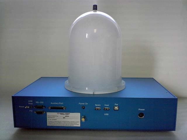
Click to zoom
Application Details
- Equipment Class
- UWB - Ultra Wideband Transmitter
- Date of Grant
- Jun 29, 2005
- Application Purpose
- Original Equipment
- Date of Application
- Aug 08, 2004
- Frequency Range
- 3100.00000000 - 7300.00000000
- Company
- General Atomics
- Country
- United States
Documents & Files
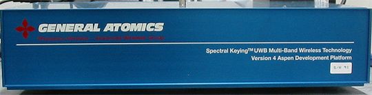
Document Text
Text extracted from the exhibit documents filed with the FCC. Open a document above to read the original.
Users Manual
Aspen TM AEVK-01 User Manual Ultra Wideband Transceiver General Atomics Photonics Division 10240 Flanders Court San Diego, CA 92121 http://photonics.ga.com/uwb Tel: (858) 457-8749 Fax: (858) 457-8746 Email: [email protected] April 2005 Version 1.0.4 Copyright General Atomics 2005 Nondisclosure Provisions This manual contains General Atomics Corporation Confidential and Proprietary information. All developers utilizing this evaluation kit and its documentation are reminded of their obligations to protect General Atomics Proprietary information. Copyright ©2005 General Atomics. All rights reserved. Trademarks Aspen and Spectral Keying are registered trademarks of General Atomics Corporation. Rights Rights to use this documentation are restricted to the terms set forth in the Terms and Conditions accompanying this AEVK-01 Evaluation Kit. Regulatory Notice This device does not comply with any RF emissions regulations in any country. Users should consult their spectrum management authorities before use. U.S. Operation : This device complies with the Part 15 of the FCC rules. Operation is subject to the following conditions: (1) this device may not cause harmful interference; (2) this device must accept any interference received, including interference that may cause undesired operation; (3) this device must be operated indoors; and (4) the emissions from equipment operated under this section shall not be intentionally directed outside of a building where the equipment is located, such as through a window or doorway, to perform an outside function, and (5) the use of outdoor mounted antennas or any other outdoor antenna infrastructure is prohibited. Operation in disregard of these conditions is a violation of 47 U.S.C. 301 and could subject the operator to serious legal penalties. Outside U.S. Operation : This Aspen TM UWB transceiver technology has not been authorized for use or commercial exploitation under the regulations on any non-U.S. government agency. Please consult with your government’s local regulatory agency to ensure proper authorizations are obtained. This document contains proprietary information subject to the terms and conditions of General Atomics Aspen Developers Program Nondisclosure Agreement 2 Table of Contents Revision History.......................................................4 Spectral Keying® Ultra Wideband Modulation..........5 Applications.............................................................7 Basic Connection....................................................10 Connecting The System For Data Streaming Operation................11 RF Test Mode.......................................................................12 Summary..........................Error! Bookmark not defined. Antenna Characteristics.........................................14 This document contains proprietary information subject to the terms and conditions of General Atomics Aspen Developers Program Nondisclosure Agreement 3 Revision History Revision Date Author Comments November 1 st , 2005 L. Chow Initial creation. March 25 th , 2005 R. Erman Added instructions on RF Test Mode March 31 st , 2005 R. Erman Moved programming portion Tech Note 4001. April 5 th , 2005 R. Erman Added Information regarding AEVK companion CD. This document contains proprietary information subject to the terms and conditions of General Atomics Aspen Developers Program Nondisclosure Agreement 4 Introduction Congratulations on your purchase of the General Atomics AEVK-01 ultra wideband (UWB) transceiver evaluation kit! This evaluation kit contains all of the hardware, software and documentation necessary to evaluate an FCC- compatible high data rate UWB transmission system. As the first generation of the Aspen TM family of UWB radios, the AEVK-01 is a discrete implementation of the Aspen TM 2000 UWB multi-chip module (MCM) based chipset, including the physical layer, baseband, and the embedded media access control (MAC) functions necessary to accomplish low-power wireless multimedia streaming. This User’s Guide describes the functional capabilities of the Aspen system, the advantages of the Spectral Keying ® (SK) modulation technique employed in the radio, its operational characteristics, and application interfaces. The AEVK- 01 is designed to provide product development OEMs and ODMs confidence in the robust RF performance of the SK-based UWB radio and provides all of information necessary to develop and test applications. Detailed timing and interface specifications are provided separately with General Atomics developer’s agreement. Spectral Keying® Ultra Wideband Modulation SK modulation is fundamentally different from other UWB approaches, optimized for robust long-range operation in high multipath application environments. The SK modulation approach divides the allocated UWB spectrum into multiple sub-bands, each with 500 MHz minimum bandwidth. This provides flexibility in selecting suitable bands (spectral agility) based on the presence of interference or regulatory constraints. In the SK modulation architecture used in the AEVK-01, information symbols are made up of 5 pulses, each sent in a different UWB sub-band. The combination of the five sub bands creates a symbol, where information is encoded in the sequence of the bands used for each pulse. Each frequency is used only once in a symbol. An individual sub band sample is shown below: This document contains proprietary information subject to the terms and conditions of General Atomics Aspen Developers Program Nondisclosure Agreement 5 Using 5 bands, the allowable symbol set is 5!=120 unique symbols. Hence the number of possible bits per symbol is log 2 (120) = 6.9 bits. Figure 1 illustrates the advantage of SK its capability to carry a large number of bits per symbol showing two typical SK symbols. The first symbol uses the sequence of sub- bands F 1 , F 2 , F 3 , F 4 , F 5 to create a unique symbol, while the second F 2 , F 5 , F 1 , F 3 , F 4 to a diffe…
Text truncated - open the document above for the full version.
Cover Letter(s)
October 14, 2004 Chief, Authorizations Branch Federal Communications Commission 7435 Oakland Mills Road Columbia, MD 21046 Re: Certification Application ID SC9AEVK1 Gentlemen, Please be advised that the following exhibits are to be held confidential on behalf of General Atomics. • Operational Description • Block Diagrams • Schematics • Parts List (Bill of Materials) This application contains technical information that General Atomics considers trade secrets and proprietary. Thank you for your attention to this matter. Regards, Pat Carson Vice President TDK RF Solutions
Cover Letter(s)
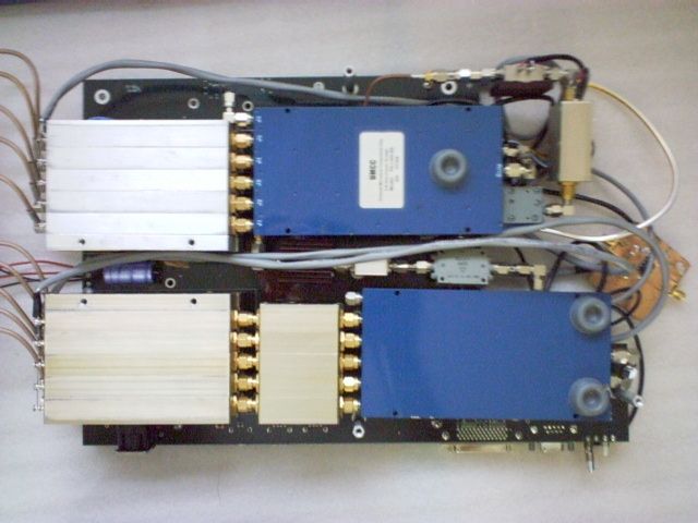
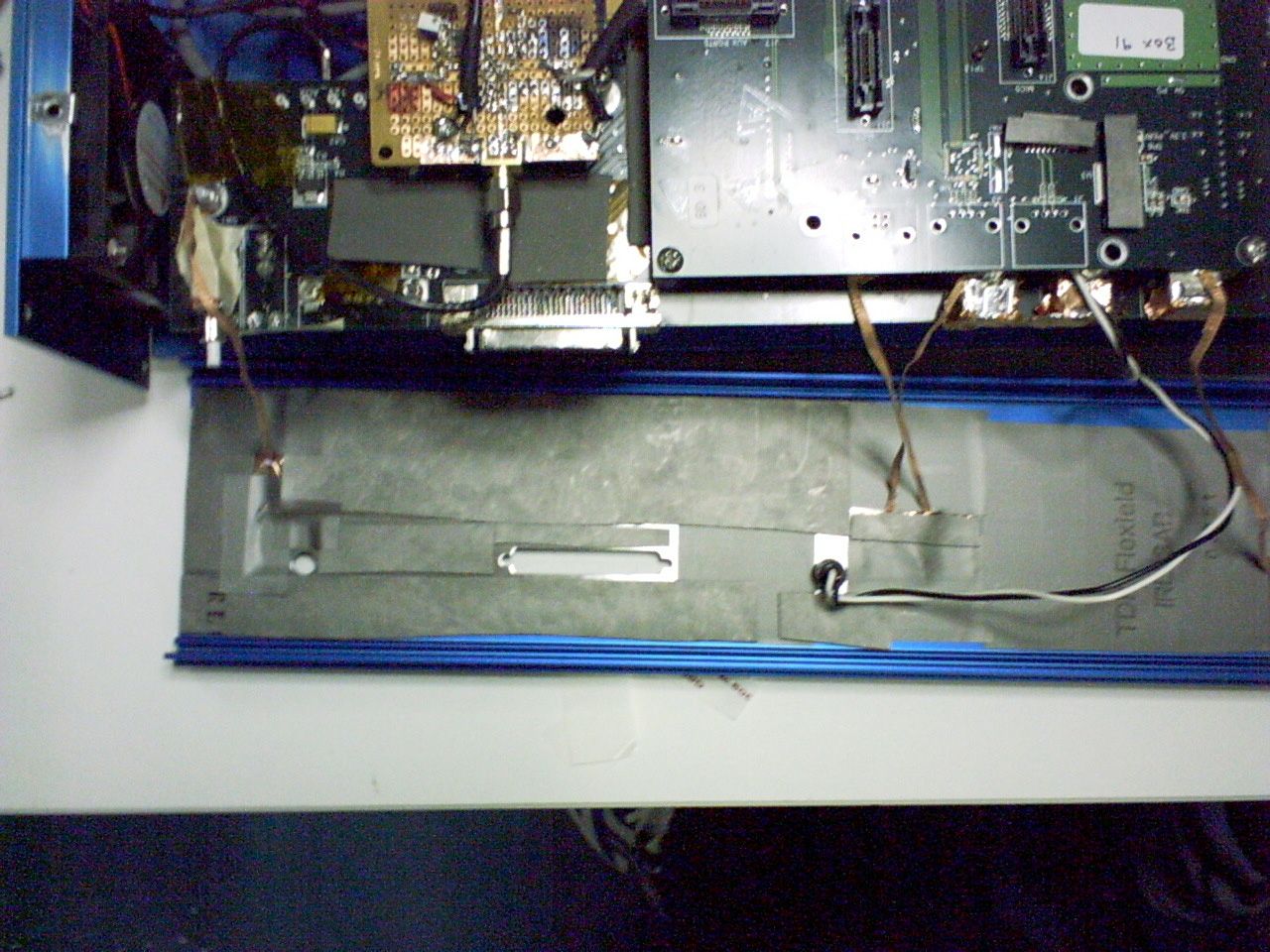
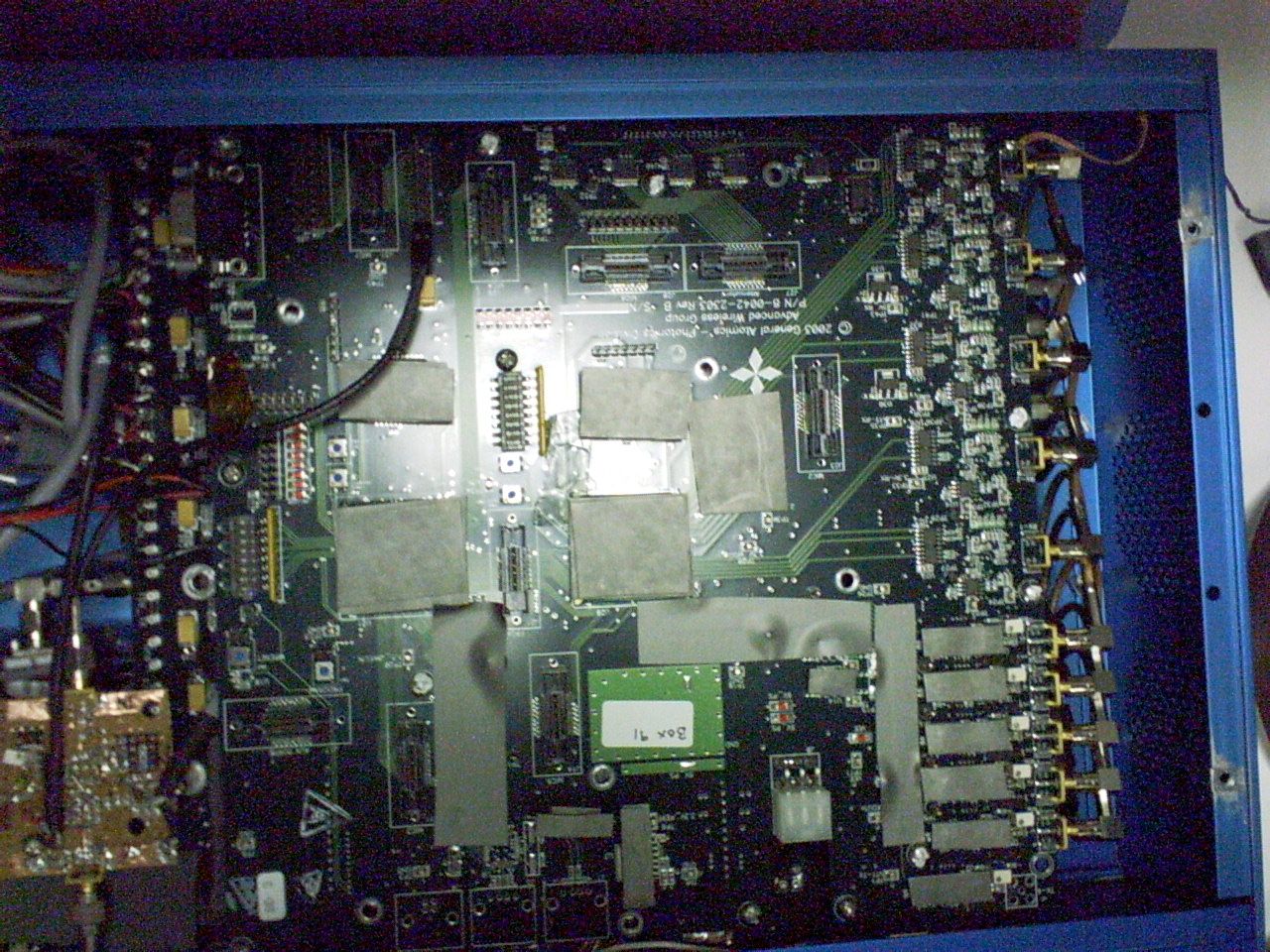
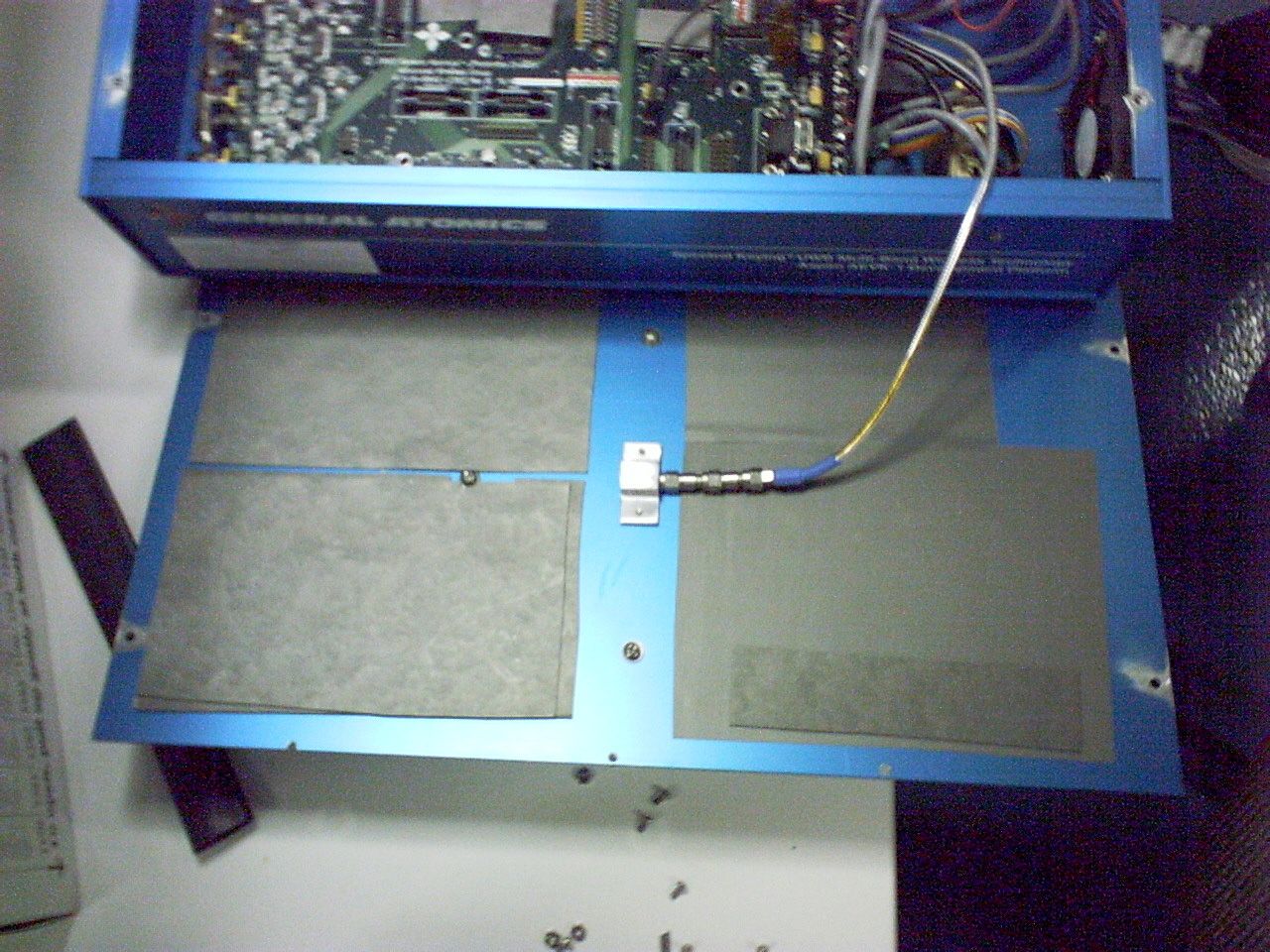
FCC ID SC9AEVK1 General Atomics EA744095 Dear Mr. Dichoso, With regards to the questions concerning the filing for General Atomics here are the answers to your questions. Correspondence reference number 28100 Q1) Spectral keying is similar to frequency hopping and frequency stepping. Measurement with the signal constant on the frequency is required. A time averaging cannot be introduced. Provide data on a low, middle and high channel. A1) As per the MBOA waiver we can operate the device in its original mode of usage. All of the relevant data is presented and passed. Q2) Although you indicated that the device is NOT a computer peripheral, the device is a computer peripheral as indicated in the manual. Indicate whether Certification or DOC approval will be obtained. If certified, then file a composite filing. If DOC approved, provide the DOC label. A2) The device will be certified as a transmitter. There are no computer interfaces on the radio for it to be used as a peripheral. All references to this in the user's manual have been removed. Q3) Provide a technical description of compliance with Section 15.517(a)5. Informing the applicant of the requirement is insufficient. A3) The technical description of compliance with Section 15.517(a)5 is now described in detail in the User's Manual on page 11. Q4) Provide clearer photo of the label for Section 15.517(f). The one submitted was unclear. A4) The revised test report has clearer photos for review. Q5) With regard to Section 4.5 of the report, indicate the frequencies and field strength of all emissions found. You had indicated that these emissions were attributed to oscillators/frequencies in the digital circuitry. Please provide information on this digital circuitry. Is it used to enable the transmitter? If not, what is it used for? Does this digital circuitry perform some other function or have some other capability? If so, what is it? A5) The shielding on the radio was improved so that all radiated emissions from digital circuitry (intentional and unintentional) fall below the more stringent UWB limit line. Therefore, there is no need to rely on the higher 15.209 limits for comparison or description of the sources. The revised test report has the results. Q6) After the above is submitted, a sample may be requested. A6) OK, please give us one week to prepare a sample. Correspondence reference number 28800 Q1) Please provide the 10 dB BW (Fl and Fh) of each of the 5 pulses. A1) Additional data included in the modified test report dated April 22, 2005 Q2) The new label photo did not include the wording required by Section 15.517(f). Please submit it. A2) This statement required from 15.5217(f) is included on Page 2 of the User's Manual under the "US Operations" of the Regulatory Notice section. According to FCC rules the manufacturer may include the statement; "This equipment may only be operated indoors. Operation outdoors is in violation of 47 U.S.C. 301 and could subject the operator to serious legal penalties." in a conspicuous location on the device or in the instruction manual supplied with the device. The manufacturer has included it in the Users Manual. Q3) It appears that the device was modified. Please clarify and if appropriate provide all appropriate photos. A3) The radio has improved out of band emissions by the addition production level flexshield material and the addition of a new rear panel with unused connectors removed. New internal photos have been sent. Best Regards Pat Carson
ID Label/Location Info
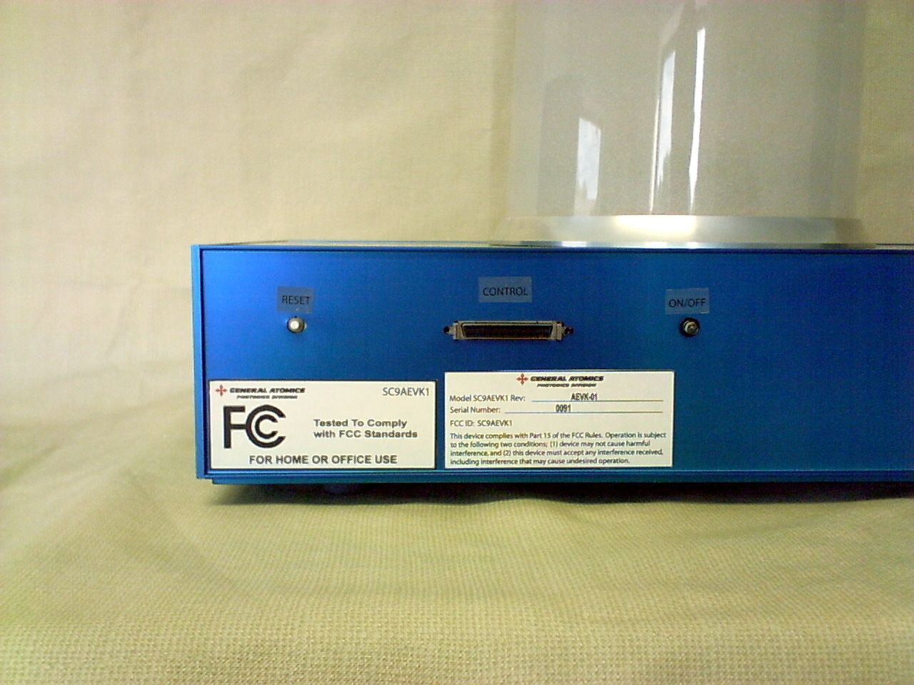
Model SC9AEVK1 Rev: ________________________________ Ser ial Number : _______________________________________ FCC ID: SC9AEVK1 This device complies with Par t 15 of the FCC Rules. Oper ation is subject t o the following two conditions; (1) device may not cause harmful interfer ence, and (2) this device must accept any interfer ence received, including interfer ence that may cause undesired oper ation. AEVK-01 0091
ID Label/Location Info
Model SC9AEVK1 Rev: ________________________________ Ser ial Number : _______________________________________ FCC ID: SC9AEVK1 This device complies with Par t 15 of the FCC Rules. Oper ation is subject t o the following two conditions; (1) device may not cause harmful interfer ence, and (2) this device must accept any interfer ence received, including interfer ence that may cause undesired oper ation. AEVK-01 0091
Test Report
Band 1 emissions using peak detector USB Mode 1MHz RBW, 3MHz VBW, 1msec averaging time, 1m distance Video Mode 1MHz RBW, 3MHz VBW, 1msec averaging time, 1m distance
Test Report
OOB Emissions The Base Band Board uses 120MHz and 240MHz digital clocks. The emissions labeled #1, #4, #5, and #11 could be attributed to 9th, 11th, 13th, and 15th harmonics of 120MHz digital clock. The emission labeled #3 would be attributed to 5th harmonics of 240MHz digital clock or 10th harmonics of 120MHz digital clock. The other emissions labeled #2, #6, #7, #8, #9, and #10 are additional spurious emission that are under the limit line. USB Mode This plot is a close up of the plot in Section 6.2.2 in the report, named USB Mode from 960MHz to 18000MHz, from 960 MHz to 2000MHz Frequency and field strength of emissions from 960MHz to 2000MHz in USB Mode, The bold letter is for emission exceeds the limit. peak frequency(MHz) emission level(dBm), H emission level(dBm), V 1m limit level(dBm) 1 1080 -62.2 -62.6 -65.8 2 1100 -67.7 -68.0 -65.8 3 1200 -66.8 -67.5 -65.8 4 1320 -65.3 -65.0 -65.8 5 1560 -66.7 -66.6 -65.8 6 1602 -66.2 -66.7 -65.8 7 1638 -65.3 -66.3 -43.8 8 1722 -66.6 -65.9 -43.8 9 1740 -65.3 -65.0 -43.8 10 1758 -65.8 -65.9 -43.8 11 1800 -64.2 -64.3 -43.8 #1 #2 #3 #4 #5 #6 #7 #8 #9 #10 #11 Video Mode This plot is a close up of the plot in Section 6.2.2 in the report, named Video Mode from 960MHz to 18000MHz, from 960 MHz to 2000MHz Frequency and field strength of emissions from 960MHz to 2000MHz in Video Mode, The bold letter is for emission exceeds the limit. peak frequency(MHz) emission level(dBm), H emission level(dBm), V 1m limit level(dBm) 1 1080 -65.6 -66.5 -65.8 2 1100 -68.6 -68.3 -65.8 3 1200 -68.1 -68.2 -65.8 4 1320 -63.5 -65.2 -65.8 5 1560 -67.4 -67.3 -65.8 6 1602 -67.5 -66.6 -65.8 7 1638 -66.0 -65.9 -43.8 8 1722 -66.4 -66.1 -43.8 9 1740 -60.4 -66.0 -43.8 10 1758 -66.2 -65.8 -43.8 11 1800 -65.3 -63.6 -43.8 #1 #2 #3 #4 #5 #6 #7 #8 #9 #10 #11
Test Report
All services undertaken are subject to the following general policy. Reports are submitted for exclusive use of the client to whom they are addressed. Their significance is subject to the adequacy and representative character of the samples and to the comprehensiveness of the tests, examinations or surveys made. This report shall not be reproduced except in full, without written consent of TDK RF Systems Inc. This report must not be used to claim product endorsement by A2LA, NVLAP nor any other agency of the US Government. Compliance report of Aspen™ AEVK-1 Customer: General Atomics Advanced Wireless Group 10240 Flanders Court San Diego, CA 92121 Date: April 15, 2005 TDK Report: 070401GArev1 Test performed by: TDK R&D Corporation 1101 Cypress Creek Rd Cedar Park, TX 78613 Technician Checked by Radiated 30 MHz to 40 GHz A. Medina K. Yata Conducted 150 KHz to 30 MHz G. Kudva K. Yata Report P. Carson R. Sutton This document contains confidential information and cannot be disclosed outside of General Atomics or any affiliated company in whole or in part without the express written permission of TDK RF Systems Inc. 535498.DOC 2 1. Executive Summary An EMC evaluation to determine compliance of the Aspen™ AEVK-1 with requirements of FCC 47 CFR Part 15, Subpart F Section 15.517 was conducted. All references are to the most current version of the Code of Federal Regulations 47 that are currently in effect. In accordance with §2.1033, the following data is presented in support of the Certification of the Aspen™ AEVK-1. The client should retain a copy of this document on file for at least 5 years after the manufacturing of the product has been discontinued. Test Description FCC 47 CFR Section Compliance Operational Limitations 15.517(a) The client has been notified of these limitations. In normal operating mode the transmitter will only send data when associated with a receiver. See section 5 for detail UWB Bandwidth 15.517(b) Yes Radiated Emissions 15.517( c), 15.209 Yes Radiated Emissions in GPS Bands 15.517(d) Yes Peak Emissions within a 50 MHz Bandwidth 15.517(e) Yes Labelling Requirements 15.517(f) The client has been notified of these requirements. See appendix for detailed photograph AC Conducted Emissions 15.207 Yes 2. Task Description 2.1. Scope Reference FCC ET Docket No. 98-153, FCC 02-48 First R&O; FCC 47 CFR, Part 15, Subpart A; FCC 47 CFR, Part 15, Subpart B; FCC 47 CFR, Part 15, Subpart C; FCC 47 CFR, Part 15, Subpart F FCC ET Docket No. 04-352, Petition for Waiver of the Part 15 UWB Regulations Filed by MBOA-SIG (Adopted: March 10, 2005) Title Revision of Part 15 of the Commission’s Rules Regarding Ultra-Wideband Transmissions Systems; Code of Federal Regulations, Part 15 Subpart A: General Code of Federal Regulations, Part 15 Subpart B: Unintentional Radiators Code of Federal Regulations, Part 15 Subpart C: Intentional Radiators Code of Federal Regulations, Part 15 Subpart F: Ultra-Wideband Operation Purpose of Test To gain FCC Certification Authorization for technical requirements for Indoor UWB Systems operating between 3.1 GHz and 10.6 GHz. Test Procedures The tests were conducted in accordance with the following documents: FCC ET Docket 98-153, FCC 02-48 First R&O ANSI C63.4: 2001: Methods of Measurement of Radio-Noise Emissions from Low-Voltage Electrical and Electronic Equipment in the Range of 9 kHz to 40 GHz FCC Code of Federal Regulations 47, Part 15 Subpart A: General FCC ET Docket No. 04-352, Petition for Waiver of the Part 15 UWB Regulations Filed by MBOA-SIG (Adopted: March 10, 2005) General Procedures FCC Code of Federal Regulations 47, Part 2 Frequency Allocations and Radio Treaty Matter: General Rules and Regulations Classification of EUT Indoor Ultra-Wideband System 2.2. Related Submittal(s)/Grant(s) None 2.3. Test Plan Reference Publication Year Title FCC 47 CFR, Part 15, Subpart A 10/2004 Code of Federal Regulations, Part 15 Subpart A: General FCC 47 CFR, Part 15, Subpart B 10/2004 Code of Federal Regulations, Part 15 Subpart B: Unintentional Radiators FCC 47 CFR, Part 15, Subpart C 10/2004 Code of Federal Regulations, Part 15 Subpart C: Intentional Radiators FCC 47 CFR, Part 15, Subpart F 10/2004 Code of Federal Regulations, Part 15 Subpart F: Ultra-Wideband Operation FCC ET Docket 98-153, FCC 02-48 First R&O 04/2002 Revision of Part 15 of the Commission’s Rules Regarding Ultra-Wideband Transmissions Systems: First Report & Order ANSI C63.4 01/2001 Methods of Measurement of Radio- Noise Emissions from Low-Voltage Electrical and Electronic Equipment in the Range of 9 kHz to 40 GHz FCC ET Docket No. 04- 352 3/2005 Petition for Waiver of the Part 15 UWB Regulations Filed by MBOA-SIG 2.4. Client Information APPLICANT Name: General Atomics Advanced Wireless Group Address: 10240 Flanders Court, San Diego, CA 92121 Contact Person: Jeff Harris MANUFACTURER Name: General Atomics Advanced Wireless Group Address: 10240 Flanders Court, San Diego, CA 92121 Contact Person: Jeff Harris 2.5. Equipment Under Test (EUT) The following information (with the exception of the date information) has been supplied by the applicant. The test results in this report pertain only to the item tested. General Brand Name Ultra-Wideband Evaluation Kit Product Name Aspen™ Model Name or Number AEVK-1 Serial Number 0091 Type of Equipment UWB Radio Transmitter Input Power Supply Type External power adapter Classification Indoor Ultra-Wideband System Technical Power Supply Requirements AC mains, 100-240 Vac, 110 VA, 50/60 Hz RF Output Rating -42.3 dB/MHz Operating Frequency Range 3.1 GHz to 7.3 GHz, 5 sub-bands Fc 1 = 3.48 GHz (Band 1) Fc 2 = 4.02 GHz (Band 2) Fc 3 = 4.56 GHz (Band 3) Fc 4 = 6.12 GHz (Band 4) Fc 5 = 6.96 GHz (Band 5) RF Output Impedance 50 Ω Channel Spacing N/A Pulse Width 4 nS Pulse Repetition Frequency 6 MHz 10 dB Bandwidth >500 MHz Modulation/Constellation Spectral Keying® Oscillators’ Frequencies 120 MHz, 3.48 GHz, 3.56 GHz, 4.02 GHz, 6.12 GHz, 6.96 GHz EUT Ports 12 Vdc External…
Text truncated - open the document above for the full version.
Contact Information
Applicant
Jeff Harris(Business Development Manager)
Technical Contact
TDK RF SolutionsKunio Yata
[email protected]512 258 9478
1101 Cypress Creek Road · Cedar Park, Texas · United States
Non-Technical Contact
Robert SuttonRobert Sutton
[email protected]512 258 9478
Test Firm
TDK RF Solutions, Inc.Robert Sutton
Technical Specifications
| # | Rule Parts | Frequency Range | Power Output |
|---|---|---|---|
| 1 | 15F | 3.10 GHz - 7.30 GHz | - |