SCOMOBISCANBarcode and RFID Reader
aitronic GmbH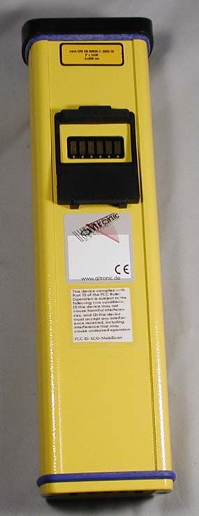
Click to zoom
Application Details
- Equipment Class
- DCD - Part 15 Low Power Transmitter Below 1705 kHz
- Date of Grant
- Jan 23, 2005
- Application Purpose
- Original Equipment
- Date of Application
- Jan 23, 2005
- Equipment Note
- Barcode and RFID Reader
- Frequency Range
- 0.12500000 - 0.12500000
- Company
- aitronic GmbH
- Country
- Germany
Documents & Files
Document Text
Text extracted from the exhibit documents filed with the FCC. Open a document above to read the original.
Users Manual
Operating Manual PMS, HTE and MobiScan Family with Standard Program Version 6 Operating Manual PMS, HTE and MobiScan Family with Standard Program Version 6 We do not only deliver our mobile Terminals with Standard Software... we are also developing custom specific • applications for these devices, • PC applications, • hardware and consult you concerning • creation of mobile data capturing concepts, • questions coming up with barcodes, • hardware problems, • PC problems. Please contact: aitronic GmbH Max-Planck-Str. 19 D-33104 Paderborn Phone: +49(0)5254/9969-0 Fax: +49(0)5254/9969-40 Internet: http://www.aitronic.de eMail: [email protected] __________________________________________________________ Copyright aitronic GmbH, 2004 All rights reserved, especially also excerpts for translation, printing, copying or similar processes. Possibility of delivery and technical modification reserved. Contents _________________________________________________________________ ____________________________________________________________________ aitronic 1 1. Introduction .................................................................... 1-1 2. Warning Hints ................................................................. 2-1 Laser Scanner Module............................................................................... 2-1 Accus......................................................................................................... 2-1 3. Security & Regulatory .................................................... 3-1 4. Care Instructions............................................................ 4-1 Care of the Scanner .................................................................................. 4-1 Dealing with the Devices Markings ............................................................ 4-1 Repairing Screen Damages....................................................................... 4-1 5. Communication/Charging Adapter ............................... 5-1 6. Installation of PC Software MTWIN............................... 6-1 7. Introduction to Operation .............................................. 7-1 Switching on/off ......................................................................................... 7-3 LCD Displays ............................................................................................. 7-3 Scanner Handling ...................................................................................... 7-4 Manually Data Entry .................................................................................. 7-5 Deleting Characters ................................................................................... 7-5 Deleting Entry Field ................................................................................... 7-5 Select next Entry Field............................................................................... 7-6 Closing Entry and storing the Record ........................................................ 7-6 8. System Functions .......................................................... 8-7 8.1 Cold Start / Initialization.......................................................................... 8-7 8.2 Reset Button ............................................................................................ 8-9 Warm Start .............................................................................................. 8-11 Cold Start / Initialization ........................................................................... 8-11 Calling the Boot Program......................................................................... 8-11 8.3 Battery Low Procedure ......................................................................... 8-12 8.4 Menu System ......................................................................................... 8-13 Calling/leaving the Menu System............................................................. 8-13 Selecting Menus ...................................................................................... 8-13 Selecting Menu Functions ....................................................................... 8-14 _________________________________________________________________ Contents aitronic ___________________________________________________________________ 2 Executing Menu Functions .......................................................................8-14 Returning to Menu System .......................................................................8-14 Menü: 1 APPLICATION............................................................................8-14 Menü: 2 DATA MEMORY.........................................................................8-15 Menü: 3 COMMUNICATION....................................................................8-15 Sub-Menü: 3 DECT Functions..................................................................8-16 Menü: 4 SETUP .......................................................................................8-17 8.5 Function Barcodes.................................................................................8-18 Commands ...............................................................................................8-18 Program Selection....................................................................................8-19 Standard Barcode Menu ..........................................................................8-20 8.6 Charging the integrated Accumulators ................................................8-26 8.7 Error Messages ......................................................................................8-27 8.8 Error Diagnostics ...................................................................................8-31 9. Software Update ............................................................. 9-1 10. Technical Data ......................................................... 10-1 Mobile Terminals PMS 1200/1500 ......................................................…
Text truncated - open the document above for the full version.
Block Diagram
ib technology Microcontroller IC Antenna Drivers Synchron Demodulator Phase Measurement Modulator Bandpass filter Amplifier and digitiser Control unit Control Register Oscillator Serial Interface 4 MHz Crystal 700μH antenna coil 5v DC supply RF Modulator/demodulator ASIC IC 125kHz carrier frequency 100ms RF OFF 10ms RF ON 100ms RF OFF 50ms RF ON (Default polling time setting) NO Tag Tag in field (Reading) MicroRWD Block Diagram Four Output signals TTL level RS232 interface LED output signals
Internal Photos
Annex C (Internal photographs of the EUT) of test report R40694a_Edition 2 EUT: MobiScan-75 Manufacturer: aitronic GmbH Examiner: Raimund BLASKDate of issue: 23 August 2004page 1 of 1 40694eut14.jpg: EUT, internal view
Operational Description
ib technology 1 Data Sheet Approvals.pdf 3 Pages Last Revised 07-07-04 MicroRWD EC and FCC Directive Conformity Background MicroRWD RFID reader device is a fully integrated 125 kHz read/write solution for Philips Semiconductors Hitag, EM Marin and Microchip RF passive transponders. It is completely housed in a 24-pin DIP package and only requires a 700 micro Henry antenna coil connected and 5v DC supply to be a fully featured “system on a chip”. The MicroRWD device incorporates a TTL level RS232 serial interface for host communication and a number of input and output pins for reading switch inputs, driving indicator LED’s and other output devices such as relays etc. These output lines can also be used to accommodate additional host interfaces such as Wiegand and clock/data protocols. The MicroRWD can be used in a standalone mode using its internal EEPROM for validating transponder serial numbers or can be connected to a host computer or microcontroller using the 9600-baud serial interface. Transponders Hitag 1, Hitag 2, EM Marin H400X and Microchip MCRF200 passive RF transponders are read/write or read only memory devices that derive their power and communicate using a modulated 125 kHz RF field created by the MicroRWD antenna coil. They can use various communication schemes and have different amounts of available memory for storing user information etc. Some of the transponders also use encryption and password authentication techniques to provide communication and data security. The transponders or tags can be packaged in a variety of forms but essentially all consist of the transponder device connected to a coil of the appropriate inductance. MicroRWD circuit description The MicroRWD module is made up of an RF ASIC IC (modulator/demodulator), a microcontroller IC and a number of R and C passive components, all of which are powered from an external 5-volt DC supply. A single 4 MHz crystal provides the oscillator-clocking signal for both ICs. The RF ASIC internally divides this to produce the 125kHz carrier frequency, which under control of the microcontroller is turned ON and OFF according to a polling duty cycle. (Default setting – 100ms OFF / 10ms ON with no tag in field and 100ms OFF / 50ms ON reading a tag in field). Because the RF field is normally turned off and is effectively only on for short periods of transponder communication, the average power consumption of the MicroRWD is very low compared to other products on the market The 125kHz carrier frequency drives a pair of FET transistors, which are connected, to an antenna coil of 700μH inductance (typically a simple 7-10cm diameter wire wound coil) with a 2nF capacitor in series. Under optimum conditions this forms a resonant circuit at the 125kHz fundamental frequency and 100v peak-to-peak and 200ma peak currents are created in the coil. This radiated carrier field has sufficient strength to power passive transponders in close proximity (up to 15cm max range typically). ib technology 2 Typical operation for MicroRWD H400X version (read-only type) is as follows: The H4001 transponder also has a small antenna coil and capacitor which is designed to resonate at 125kHz so that when the MicroRWD reader field is turned on they form an inductive link (like an air-cored transformer). The transponder antenna picks up the carrier signal and rectifies it internally to provide sufficient power for it’s logic and memory to wake-up. The 64-bit content of the internal memory is encoded into a Manchester code bit stream that is used to “Amplitude Modulate” (ASK) the received carrier frequency at a rate of RF/64 (2 kbaud). Using the inductive coupling principle, the MicroRWD reader antenna picks up this modulation. MicroRWD antenna signal levels for a transponder in close proximity to the antenna are typically less than 100mv ASK modulation on the 100v peak-to-peak carrier. The RF ASIC device demodulates the data and corrects for phase shift. Finally the microcontroller reads the Manchester bit stream, decodes it further and checks for parity and other data errors before providing the data in a convenient protocol form on it’s TTL level RS232 interface. The microcontroller also has four I/O lines that can supply up to 25ma sink current to drive external loads. Two I/O lines are also specifically allocated to drive Red and Green LEDS to give visual indication of valid card in the field etc. Microcontroller IC Antenna Drivers Synchron Demodulator Phase Measurement Modulator Bandpass filter Amplifier and digitiser Control unit Control Register Oscillator Serial Interface 4 MHz Crystal 700μH antenna coil 5v DC supply RF Modulator/demodulator ASIC IC 125kHz carrier frequency 100ms RF OFF 10ms RF ON 100ms RF OFF 50ms RF ON (Default polling time setting) NO Tag Tag in field (Reading) MicroRWD Block Diagram Four Output signals TTL level RS232 interface LED output signals ib technology 3 Typical Characteristics: Supply VDD: 5v (+/- 10%) Carrier frequency: 125kHz RF OFF/ON duty cycle 100ms:10ms (no tag in field), 100ms/50ms (reading tag data) Max antenna voltage (optimum conditions) 100v peak-to-peak at carrier frequency Max antenna current (optimum conditions) 200ma peak Transponder data rate: 2k baud (RF/64) Manchester coded Back-modulation: ASK Serial interface: TTL level RS232. 9600 baud, 8 bits, 1 stop, no parity, CTS handshaking Approvals As a low power active transmission device in the 125 kHz frequency band the MicroRWD has been designed to conform to the European Community R&TTE (Radio and Telecommunication Terminal Equipment) Directive (99/5/EC) and specifically EN 300 330. The frequency band below 135 kHz is license free and as such represents a straightforward approval path. Ultimately the conformity would depend on the user following the design guidelines provide by IB Technology with regard to designing the antenna coil and associated circuitry. The final application or product would also have to comply with EMC (Electro Magnetic Compatibi…
Text truncated - open the document above for the full version.
Test Report
Königswinkel 10 32825 Blomberg Germany Phone+49 5235 9500-0 Fax+49 5235 9500-10 TEST REPORT Test Report Reference: R40694a Edition 2 Equipment under Test: MobiScan-75 Serial Number: 50000900 Applicant: aitronic GmbH Manufacturer: aitronic GmbH FCC ID: Not available Test Laboratory (CAB) accredited by DATech e.V. in compliance with DIN EN ISO/IEC 17025 under the Reg. No. TTI-P-G071/94-11 and listed by FCC 31040/SIT1300F2 TEST REPORT REFERENCE: R40694a Edition 2 Examiner: Raimund BLASKDate of issue: 23 August 2004Page 2 of 23 Contents:Page 1IDENTIFICATION.....................................................................................................................................3 1.1APPLICANT....................................................................................................................................3 1.2MANUFACTURER..........................................................................................................................3 1.3DATES............................................................................................................................................3 1.4TEST LABORATORY......................................................................................................................4 1.5RESERVATION...............................................................................................................................4 1.6NORMATIVE REFERENCES.........................................................................................................4 1.7TEST RESULTS..............................................................................................................................4 2TECHNICAL DATA OF EQUIPMENT......................................................................................................5 2.1DEVICE UNDER TEST...................................................................................................................5 2.2PERIPHERY DEVICES...................................................................................................................5 2.3MODIFICATIONS............................................................................................................................5 3OPERATIONAL STATES AND PHYSICAL BOUNDARIES.....................................................................6 4LIST OF TEST MODULES.......................................................................................................................7 4.1EMISSION.......................................................................................................................................7 METHODS OF MEASUREMENT................................................................................................................8 4.2RADIATED EMISSIONS 9 kHz to 30 MHz......................................................................................8 4.3RADIATED EMISSIONS 30 MHz to 1 GHz.....................................................................................10 5TEST RESULTS EMISSION TEST..........................................................................................................13 5.1PRELIMINARY RADIATED EMISSION TEST (9 kHz to 30 MHz)..................................................13 5.2PRELIMINARY RADIATED EMISSION TEST (30 MHz to 1 GHz).................................................15 5.3FINAL RADIATED EMISSION TEST (9 kHz to 30 MHz)................................................................17 5.4BAND EDGE COMPLIANCE..........................................................................................................18 6TEST EQUIPMENT AND ANCILLARIES USED FOR TESTS.................................................................19 7LIST OF ANNEXES..................................................................................................................................23 TEST REPORT REFERENCE: R40694a Edition 2 Examiner: Raimund BLASKDate of issue: 23 August 2004Page 3 of 23 1IDENTIFICATION 1.1APPLICANT Name:aitronic GmbH Address:Max-Planck-Str. 19 33104 Paderborn Country:Germany Name for contact purposes:Mr. Bönninghoff Phone:+49-(0)-5254-9969-24 Fax:+49-(0)-5254-9969-40 Mail address:[email protected] Applicant represented during the test by the following person: Mr. Bönninghoff 1.2MANUFACTURER Name:aitronic GmbH Address:Max-Planck-Str. 19 33104 Paderborn Country:Germany Name for contact purposes:Mr. Bönninghoff Phone:+49-(0)-5254-9969-24 Fax:+49-(0)-5254-9969-40 Mail address:[email protected] Applicant represented during the test by the following person: Mr. Bönninghoff 1.3DATES Date of receipt of test sample:21 July 2004 Start of test:21 July 2004 Finish of test:21 July 2004 TEST REPORT REFERENCE: R40694a Edition 2 Examiner: Raimund BLASKDate of issue: 23 August 2004Page 4 of 23 1.4TEST LABORATORY The tests were carried out at:PHOENIX TEST-LAB GmbH Königswinkel 10 D-32825 BlombergPhone: +49 (0) 52 35 / 95 00-0 GermanyFax:+49 (0) 52 35 / 95 00-10 Test engineer:Raimund BLASK24 August 2004 NameSignatureDate Test report checked: Wilfried MEIER24 August 2004 NameSignatureDate Stamp 1.5RESERVATION T h i s t e s t r e po r t i s o n l y v a l i d i n i t s o r i g i n a l f o r m . Any reproduction of its contents without written permission of the accredited test laboratory PHOENIX TEST-LAB GmbH is prohibited. The test results herein refer only to the tested sample. PHOENIX TEST-LAB GmbH is not responsible for any generalisations or conclusions drawn from these test results concerning further samples. Any modification of the tested samples is prohibited and leads to the invalidity of this test report. Each page necessarily contains the PHOENIX TEST-LAB Logo and the TEST REPORT REFERENCE. 1.6NORMATIVE REFERENCES [1] ANSI C63.4-2001 American National Standard for Methods of Measuring of Radio-Noise Emissions from Low-Voltage Electrical and Electronic Equipment in the Range of 9 kHz to 40 GHz. [2] FCC 47 CFR Part 15 (23 April 2004) Radi…
Text truncated - open the document above for the full version.
Test Setup Photos
Annex A (Photographs of the test set-up) of test report R40694a_Edition 2 EUT: MobiScan-75 Manufacturer: aitronic GmbH Examiner: Raimund BLASKDate of issue: 23 August 2004page1 of 3 40694emi5.jpg: Test set-up preliminary radiated emission measurement 9 kHz to 30 MHz Annex A (Photographs of the test set-up) of test report R40694a_Edition 2 EUT: MobiScan-75 Manufacturer: aitronic GmbH Examiner: Raimund BLASKDate of issue: 23 August 2004page2 of 3 40694emi7.jpg: Test set-up preliminary radiated emission measurement 30 MHz to 1 GHz Annex A (Photographs of the test set-up) of test report R40694a_Edition 2 EUT: MobiScan-75 Manufacturer: aitronic GmbH Examiner: Raimund BLASKDate of issue: 23 August 2004page3 of 3 40694emi8.jpg: Test set-up final radiated emission measurement 9 kHz to 30 MHz
Contact Information
Applicant
Manfred Kell(Dipl. Ing.)
Technical Contact
aitronic GmbHKlaus B�nninghoff
[email protected]+49 (0) 5254 9969 0
Max-Planck-Str. 19 · Paderborn · Germany
Non-Technical Contact
aitronic GmbHManfred Kell
[email protected]+49 (0) 5254 9969 0
Test Firm
Phoenix TestLab GmbHH. Altmaier
Technical Specifications
| # | Rule Parts | Frequency Range | Power Output |
|---|---|---|---|
| 1 | 15C | 0.125 MHz - 0.125 MHz | - |