SDECN200405182.4 GHz Wireless (VGA to TV) Audio/Video Tx
Shanghai Fullband Technologies Co., Ltd.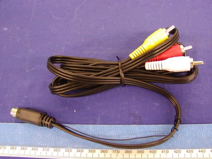
Click to zoom
Application Details
- Equipment Class
- DXX - Part 15 Low Power Communication Device Transmitter
- Date of Grant
- Jul 29, 2004
- Application Purpose
- Original Equipment
- Date of Application
- Jul 29, 2004
- Equipment Note
- 2.4 GHz Wireless (VGA to TV) Audio/Video Tx
- Frequency Range
- 2414.00000000 - 2468.00000000
- Country
- China
Documents & Files
Document Text
Text extracted from the exhibit documents filed with the FCC. Open a document above to read the original.
Users Manual
FLY Image 5000 2.4G Wireless (VGA to TV) Audio/Video Transmitter and Receiver User’s Manual Shanghai Fullband Technologies Co., Ltd Content 1. Introduction .................................................................................1 1.1 Overview.....................................................................................1 1.2 Main Features..............................................................................1 2. Check the Package Before Use............................................................1 2.1 One Unit of Transmitter..................................................................1 2.2 One Unit of Receiver........................................................................1 2.3 One Unit of Remote Control...............................................................1 2.4 One Unit of T-shaped VGA HDB15MTO HDB15F/MD8MCable: 2.5 Two Units of MD6MTO RCAMA/V cables 2.6 One Unit of Audio DC3.5MTO RCAF*2 cables: 2.7 Two Units of Power Adaptors 2.8 One Load of 75 2.9 One Book of Direction 2.10One set of wireless IR Keyboard&Mouse 3. Functions 3.1 VGA to VIDEO 3.2 2.4GHz wireless A/v Transmitter and Receiver 3.3 IR wireless Remote 3.4 433MHz IR Extender 4. How to connect 4.1 Connect the Transmitter 4.2 Connect the Receiver 4.3 Connect the IR wireless Keyboard&Mouse with PC Box 4.4 Connect the adaptor, plug into the power outlet 5. Operations 5.1 Adjust the channel 5.2 Turn on the A/V source and the A/V display 5.3 Turn on the switch of the elec. Power 5.4Long distance remote 5.5 Enjoying the high quality A/V entertainment FLY Image 5000 brings to you 6. Trouble Shooting 6.1 No picture or sound 6.2 Interference in the Image and Sound 7. Specifications 7.1 Transmitter 7.2 Receiver The Fullband’s Quality Guarantee Federal Communication Commission Interference Statement This equipment has been tested and found to comply with the limits for a Class B digital device, pursuant to Part 15 of the FCC Rules. These limits aredesignedtoprovidereasonableprotectionagainst harmful interference in a residential installation. Yhis equipment generates, uses and can radiate radio frequency energy and, if not installed and used in accordance with the instructions, may cause harmful interference to radio communications. However, there is no guarantee that interference will not occur in a particular installation. If this equipment does cause harmful interference to radio or television reception, which can be determined by turning the equipment off and on, the user is encouraged to try to correct the interference by one of the following measures,and on, the user is encouraged to try to correct the interference by one of the following measures: - Reorient or relocate the receiving antenna. - Increase the separation between the equipment and receiver. - Connect the equipment into an outlet on a circuit different fromthat to which the receiver is connected. - Consult the dealer or an experienced radio/TV technician for help. RF Exposure: To comply with FCCRFexposure compliance requirements, the antenna used for this transmitter must be installed to provide a separation distance of at least 20cmfromall persons and most not be co-located or operating in conjunction with any other antenna or transmitter. FCCCaution:Toassurecontinuedcompliance, (example-useonly shieldedinterface cables whenconnectingtocomputer or peripheral devices). Any changes or modifications not expressly approved by the partyresponsiblefor compliancecouldvoidtheuser'sauthorityto operate this equipment. 1. Introduction 1.1Overview Fly Image 5000 is a new product we put on the market, which has powerful functions integrating the features of our series wireless transmission products. Adopting the advanced 2.4GHz wireless transmission technology, it is interference resistant and can be moved freely in the certain distance. By using Fly Image 5000, you can get access to Internet, surfing on Internet, or order any online movies on TVor any monitor for displaying. Matched with wireless IR remote controller (the combinationof keyboard&mouse), youcancontrol the televisioninthelivingroomwhileusingyourcomputerinthesanctum simultaneously. It is a great breakthrough in family entertainment, since it realizes the resources sharing indeed and is different from the traditional applications. 1.2Key Features There are 4 channels, and the frequency scope ranges from 2.400GHz to 2.483GHz; In order to increase the flexibility and reliability, we prepare four selectable channels (2.414GHZ, 2.432GHz, 2.450GHz, 2.468GHz); 2.4 GHz wireless transmitter and receiver with 4 selectable channels (Tact Switch); Multiple-operationmodels:one-to-one(1Txto1Rx)onthesamechannel; one-to-multiple (1Tx to nRx) on the same channel; multiple-to-multiple(nTx to nRx) on up to 4 channels work simultaneously at the same area. Pal and NTSC video format available The refresh rate and max resolution of VGAinput is up to 150Hz and 2048x1546 respectively; Support the conversion fromVGAto VIDEO, video and audio as well as stereo transmission in the form of PAL and NTSC; Remote control PCA/V sources with 433MHz IR Extender Clear and sharp images video and stereo audio quality output from the receiver The effective distance of wireless transmission is within 300 feet in open areas. Working temperature ranges from 0 C to + 60 C Compact Size and2.4GHz RFmodule antennas of transmitter andreceiver are embedded in the housing No software is required Control PC on TV with the remote control combining keyboard and mouse FCC and CE certifiedPatent numberDI03-1055-XC26 Compatible with Camcorder or COMS camera application Receiver wirelessly accept VGA/Video/audiosignals fromtransmitter andoutput connected to TV, LCDTVmonitor, PDP TV, VCR, Digital Video recorder, video projector, speaker, or any device with video/audio input Transmitter can be connected to VGA card and sound card of any PC, and wirelessly transmit video/audio signals to receiver long range away. 2. Check Package …
Text truncated - open the document above for the full version.
External Photos
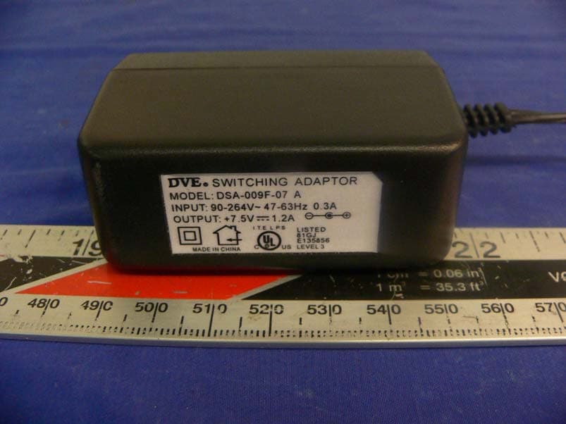
EXHIBIT C - EUT EXTERNAL PHOTOGRAPHS EUT – Chassis Front View EUT – Chassis Rear View Power Adapter View VGA Cable AV Cable I AV Cable II
ID Label/Location Info
EXHIBIT A - FCC ID LABEL INFORMATION Proposed FCC ID Label Specifications : Text is black or white in color and is left justified. Labels are silk- screened and shall be “permanently affixed” at a conspicuous location on the EUT. Proposed Label Location on EUT Rear View of EUT / FCC ID Label FCC ID: SFBCN20040518 This device complies with Part 15 of the FCC Rules. Operation is subject to the following two conditions: (1) this device may not cause harmful interference, and (2) this device must accept any interference received, including interference that may cause undesired operation. 2.1875" 1.0" FCC IDL: Q74ZT812 This device complies wi th Part 15 o the FCC Rules. Operat ion is subject to t he fol low ing two conditions: (1) this device may not cause harmful interference, and (2) this device must accept any interference received, including i nterference that may cause undesired operation. 2.1875" 1. 0 "
Internal Photos
EXHIBIT C - EUT INTERNAL PHOTOGRAPHS 75 Load View I 75 Load View II EUT – Cover off View EUT – Component View with Shielding EUT – Component View without Shielding EUT – Solder View EUT – Antenna View
Test Report
Note: The test report is specially limited to the above company and the product model only. It may not be duplicated without prior written consent of Bay Area Compliance Laboratory Corporation. This report must not be used by the client to claim product certification, approval, or endorsement by NVLAP, NIST or any agency of the US Government. FCC PART 15 Subpart C EMI MEASUREMENT AND TEST REPORT For Shanghai Fullband Technologies Co., Ltd. Suite 213-215, Building 22, 498 Guo Shoujing Rd. Shanghai 201203, P.R. China FCC ID: SDECN20040518 This Report Concerns: Original Report Equipment Type: 2.4GHz Wireless (VGA to TV) Audio/Video, Transmitter Test Engineer: Ling Zhang Report No.: R0406115(T) Report Date: 2004-07-16 Reviewed By: Benjamin Jin Prepared By: Bay Area Compliance Laboratory Corporation 230 Commercial Street Sunnyvale, CA 94085 Tel (408) 732-9162 Fax (408) 732-9164 Shanghai Fullband Technologies Co., Ltd. FCC ID: SDECN20040518 Report # R0406115Rpt.doc Page 2 of 19 FCC Part 15.249 Test Report TABLE OF CONTENTS GENERAL INFORMATION.......................................................................................................................................3 PRODUCT DESCRIPTION FOR EQUIPMENT UNDER TEST (EUT) ....................................................................................3 OBJECTIVE...................................................................................................................................................................3 RELATED SUBMITTAL(S)/GRANT(S).............................................................................................................................3 TEST METHODOLOGY..................................................................................................................................................3 TEST FACILITY.............................................................................................................................................................3 SYSTEM TEST CONFIGURATION ..........................................................................................................................5 DESCRIPTION OF TEST CONFIGURATION......................................................................................................................5 EQUIPMENT MODIFICATIONS.......................................................................................................................................5 LOCAL SUPPORT EQUIPMENT LIST AND DETAILS........................................................................................................5 EXTERNAL I/O CABLING LIST AND DETAILS...............................................................................................................5 POWER SUPPLY INFORMATION.....................................................................................................................................5 CONFIGURATION OF TEST SYSTEM..............................................................................................................................6 TEST SETUP BLOCK DIAGRAM.....................................................................................................................................6 SUMMARY OF TEST RESULTS ...............................................................................................................................7 §15.203 - ANTENNA REQUIREMENT......................................................................................................................8 STANDARD APPLICABLE..............................................................................................................................................8 ANTENNA CONNECTED CONSTRUCTION......................................................................................................................8 § 15.249 (C) - CONDUCTED EMISSIONS TEST DATA .........................................................................................9 MEASUREMENT UNCERTAINTY....................................................................................................................................9 EUT SETUP..................................................................................................................................................................9 SPECTRUM ANALYZER SETUP......................................................................................................................................9 TEST EQUIPMENT LIST AND DETAILS...........................................................................................................................9 TEST PROCEDURE........................................................................................................................................................9 ENVIRONMENTAL CONDITIONS..................................................................................................................................10 SUMMARY OF TEST RESULTS.....................................................................................................................................10 CONDUCTED EMISSIONS TEST DATA.........................................................................................................................10 PLOT OF CONDUCTED EMISSIONS TEST DATA...........................................................................................................10 §15.209(A) - RADIATED EMISSION DATA ...........................................................................................................13 MEASUREMENT UNCERTAINTY..................................................................................................................................13 EUT SETUP................................................................................................................................................................13 SPECTRUM ANALYZER SETUP..................................................................................................…
Text truncated - open the document above for the full version.
Test Setup Photos
EXHIBIT B - TEST SETUP PHOTOGRAPHS Conducted Emission Radiated Emission
Contact Information
Applicant
Kenneth Zhang(President & CEO)
Test Firm
Bay Area Compliance LaboratoryJohn Chan
Technical Specifications
| # | Rule Parts | Frequency Range | Power Output |
|---|---|---|---|
| 1 | 15C | 2.41 GHz - 2.47 GHz | - |
Other Applications from Shanghai Fullband Technologies Co., Ltd.
SDECN20050808
Aug 30, 2005Wireless PC-to-TV (Pro PC/TV Wireless)
Equipment Class
DXX - Part 15 Low Power Communication Device Transmitter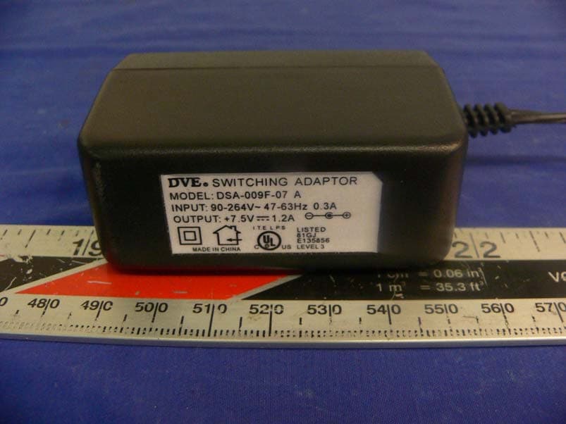
SDECN20050608
Jul 17, 20052.4GHz Wireless A/V (Pro A/V Media Extender) TX
Equipment Class
DXX - Part 15 Low Power Communication Device Transmitter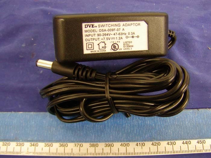
SDECN20041028
Dec 07, 20042.4GHz wireless RF&A/V to A/V transmission
Equipment Class
DXX - Part 15 Low Power Communication Device Transmitter