SDGGKB7U-3B60Dimming Receiver of Wireless 2-way System
GUANGZHOU GKB ELECTRIC CO., LTD.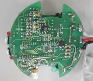
Click to zoom
Application Details
- Equipment Class
- DSR - Part 15 Remote Control/Security Device Transceiver
- Date of Grant
- Dec 28, 2004
- Application Purpose
- Original Equipment
- Date of Application
- Dec 28, 2004
- Equipment Note
- Dimming Receiver of Wireless 2-way System
- Frequency Range
- 433.90000000 - 433.90000000
- Country
- China
Documents & Files
Document Text
Text extracted from the exhibit documents filed with the FCC. Open a document above to read the original.
Cover Letter(s)
PDF 文件使用 "pdfFactory Pro" 试用版本创建 www.fineprint.com.cn
Cover Letter(s)
Subject: AN04T4339 FCC ID: SDGGKB7U-3B60 Dimming Receiver of Wireless 2-way Intelligent Control System Assessment Number: AN04T4339 Question #1: The user information required in FCC15.21 had been added in the user manual. Question #2: Please see the document named AN04T4339 setup photos FCC2004-0005 . Question #3, #8 and #9: The component used as oscillator is CC1000, you can see it in the top right corner of the Schematic Diagram. The CC1000 is an ultra-low-power single-chip RF transceiver, it is used for short-range wireless communication. The key features of CC1000 component are: single-chip RF transceiver, single-port antenna connection (pin 8), programmable frequency and output power. The pins (PALE, PDATA and PCLK) are connected to microprocessor MSF430, the pin connected to PDATA of CC1000 must be bi-directional for transmitting and receiving functions. The statement describing how the device operates please see the file named AN04T4339 Functional Block Diagram. Question #4: Power Line conducted emission testing had been done with Neutual line and Hot line. During testing, ESH3-Z5 LISN and ESCS30 testing receiver were used, phase L1, phase N and PE ground are used for the final measurement. We have modified our test report and added two columns of phase in the tables on page 8 and 10. Question #5: One column indicating calibration date of each test equipment in Appendix A on the last page of the test report had been added. Question #6: Thank you for your suggestion, we’ll use the unit dBuV/m instead uV/m next time and list frequencies, actual readings and results in the test tables. But I think that it is not necessary to list antenna factors and cable factors in the test table. Because test receiver ESCS30 and ESI26 can calculate the transducer factor on the basis of sampling points, which are defined by frequency and transducer factor and the unit that determines the unit of the level display. For frequency between the known sampling points the transducer factor is approximated using modified spline interpolation. The test results listed in the test tables and displayed in the scan graphs have been amended by the testing instrument, so the test engineer needn’t recalculated the test results. Is that OK? Question #7: Thank you again. Question #10: Class/Severity on page 7 of the test report had been taken out. Question #11: The duty cycle plot and duty cycle correction are on page 19 of the test report named AN04T4339 test report FCC2004-0005. You can see the entire period of pulse train, the number of pulses and the length of the pulse in this plot. The calculation is above the plot. If you have any other questions, please let me known immediately. Thank you for your cooperation. Best wishes, Wang Xiaoyan EMC Testing Dept. of GTIHEA Helen Zhao -----Original Message----- From: Compliance Certification Services [mailto:[email protected]] Sent: Tuesday, November 16, 2004 4:04 PM To: Helen Zhao Subject: GUANGZHOU GKB ELECTRIC CO., LTD., FCC ID: SDGGKB7U-3B60, Assessment NO.: AN04T4339, Notice#1 Question #1: The user manual does not contain user information required in FCC15.21. Please add the following statement into the user manual: "Changes or modifications not expressly approved by the party responsible for compliance could void the user's authority to operate the equipment." Question #2: Please provide setup photos of both front view and rear view. Question #3: The user manual said the device is one part of Wireless 2-Way Intelligent Control System. Please explain what kind of signals the receiver will send to the control panel. Please explain why the test report said the device is an intentional radiator, however fundamental field strength is reported undetectable. If the device is a receiver only, without transmission function, please remove 15.231 test data including duty-cycle and 20dB bandwidth measurements from the test report, but keep the data per 15.107 and 15.109 requirements. Question #4: Based upon ANSI C63.4, Power Line conducted emission testing must be done with Neutual line and hot line. But the test report does not indicate clearly that both lines have been investiaged. Question #5: Please add one more column to indicate calibration date of each Test Equipment listed on the last page of the test report. Question #6: It's suggested in future, on the test tables, you list frequencies, actual readings, Antenna factors, cable factors, duty cycle factors, results(after calculation), compared with FCC limits. (If the limit is in the unit of dBuV/m, please just use the same unit, do not use uV/m for instance.) Question #7: This is for your information, for two-way devices, since they can transmit and receive at the same time, the proper "Equipment of Class" should be "DSR - Part 15, Remote Control/Security Device transceiver" instead of "DSC - Part 15, Security/Remote Control Transmitter." For receiver only device, the proper "Equipment of Class" should be "CRR - Part 15, Superregenerated receiver" if it is a Superregenerated receiver or "CYY - Part 15 Communication Receiver used w/Part 15 TX" if it it is not a superregenerative receiver. Please answer the following questions only when the device is a transceiver(can transmit and receive): Question #8: Please provide Functional Block Diagram showing frequency of all oscillators in the device. Question #9: Please provide Operational Description to brief describe the circuit functions of the device along with a statement describing how the device operates. Question #10: Page 7 of the test report indicates Class B as Class/Severity. Please take it out since Class B is not applied to intentional radiators. Question #11: It shows the duty cycle correction factor is -22.4dB, but there are no enough plots to support it. Please provide additional duty cycle plot to show the entire period of pulse train, the nujber of pulses, and the length of the pulse. To... Cc... Bcc... Subject: FW: GUANGZHOU GKB ELECTRIC CO., LTD., FCC ID: S…
Text truncated - open the document above for the full version.
External Photos
AN04T4339 FCC ID: SDGGKB7U-3B60 Dimming Receiver of Wireless 2-way Intelligent Control System Outlook: Front View of the EUT Rear View of the EUT
ID Label/Location Info
AN04T4339 FCC ID: SDGGKB7U-3B60 Dimming Receiver of Wireless 2-way Intelligent Control System Nameplate: Statement: This device complies with Part 15 of the FCC Rules. Operation is subject to the following two conditions: (1) this device may not cause harmful interference, and (2) this device must accept any interference received, including interference that may cause undesired operation. Note: The statement is in the Operating Instructions because of the size of nameplate Position of the Nameplate Use direction 1. Model No.: GKB7U-3B/60 2. Voltage: AC110V±10% 60Hz Max load: 2A 3. Red line -- live wire, black line -- neutral wire, white line -- load wire 4. Applicable load: 5. M1 key is for system code, M2 key is for receiver code setting. Please follow the use manual to set the system code and the receiver code. FCC ID: SDGGKB7U-3B60 GUANGZHOU GKB ELECTRIC CO., LTD.
Internal Photos
AN04T4339 FCC ID: SDGGKB7U-3B60 Dimming Receiver of Wireless 2-way Intelligent Control System Structure of internal wires: Inner Circuit Top View Inner Circuit Bottom View AN04T4339 FCC ID: SDGGKB7U-3B60 Dimming Receiver of Wireless 2-way Intelligent Control System Inner Circuit Side View
Test Report
TEST REPORT Guangzhou Testing & Inspection Institute for Household Electrical Appliances 广州日用电器检测所 广州日用电器检测所广州日用电器检测所 广州日用电器检测所 GTIHEA 国家日用电器质量监督检验中心 国家日用电器质量监督检验中心国家日用电器质量监督检验中心 国家日用电器质量监督检验中心 Add.: 204 Xingang West Road Guangzhou 510302 P.R. China Telephone: 86-20-84451692 Fax: 86-20-84183160 E-mail: EMC@ GTIHEA.COM EUT : Dimming Receiver of Wireless 2-way Intelligent Control System MODEL/TYPE : GKB7U-3B/60 CLIENT : GUANGZHOU GKB ELECTRIC CO., LTD. FCC ID : SDGGKB7U-3B60 Classification of Test : COMMISSION TEST Test Report No.: FCC2004-0005 Guangzhou Testing & Inspection Institute for Household Electrical Appliances GTIHEA Test Report No. FCC2004-0005 Page2of33 Client Name: GUANGZHOU GKB ELECTRIC CO., LTD. Address: No. 98, Hedong Rd., Fangcun District, Guangzhou, Guan gdong Province, P. R. China Manufacturer Name: GUANGZHOU GKB ELECTRIC CO., LTD. Address: No. 98, Hedong Rd., Fangcun District, Guangzhou, Guangdong Province, P. R. China Equipment under Test Name : Dimming Receiver of Wireless 2-way Intelligent Control System Model/ type : GKB7U-3B/60 FCC ID : SDG GKB7U-3B60 Trade mark : GKB Serial no. : — Sampling : — Date of Receipt. 2004.08.15 Date of Testing 2004.08.15-2004.09.07 Test Specification Test Result FCC PART 15 Subpart C, 2004 PASS Evaluation of Test Result This device complies with the requirements of Federal Communications Commission (FCC) Rules and Regulations Part 15. Issue Date: Tested by: Reviewed by: Approved by: Chen Jing Name Signature Wang Xiaoyan Name Signature Name Signature Other Aspects: NONE Abbreviations: OK, Pass = passed Fail = failed N/A= not applicable EUT= equipment, sample(s) under tested This test report relates only to the EUT, and shall not be reproduced except in full, without written approval of GTIHEA. Guangzhou Testing & Inspection Institute for Household Electrical Appliances GTIHEA Test Report No. FCC2004-0005 Page 3 of 33 Contents 1. GENERAL PRODUCT INFORMATION...................................................................................4 1.1 PRODUCT FUNCTION...........................................................................................................4 1.2 RATINGS AND SYSTEM DETAILS.........................................................................................4 1.3 INDEPENDENT OPERATION MODES....................................................................................4 1.4 SUBMITTED DOCUMENTS....................................................................................................4 2. TEST SITES..........................................................................................................................5 2.1 TEST FACILITIES.................................................................................................................5 2.2 DESCRIPTION OF NON-STANDARD METHOD AND DEVIATIONS.........................................5 2.3 LIST OF TEST AND MEASUREMENT INSTRUMENTS............................................................5 3. TEST SET-UP AND OPERATION MODES..............................................................................6 3.1 PRINCIPLE OF CONFIGURATION SELECTION......................................................................6 3.2 PHYSICAL CONFIGURATION FOR TESTING.........................................................................6 3.3 TEST OPERATION MODE AND TEST SOFTWARE................................................................6 3.4 SPECIAL ACCESSORIES AND AUXILIARY EQUIPMENT.......................................................6 3.5 COUNTERMEASURES TO ACHIEVE EMC COMPLIANCE....................................................6 4. EMISSION TEST RESULTS (INTENTIONAL RADIATOR).........................................................7 4.1 CONDUCTED EMISSION (0.15MHZ~30MHZ).....................................................................7 4.2 RADIATED EMISSION (ABOVE30 MHZ) ............................................................................12 4.3 20DB BANDWIDTH OF FUNDAMENTAL EMISSION............................................................25 5. PHOTOGRAPHS & NAMEPLATES OF THE EUT.................................................................27 6. PHOTOGRAPH OF THE TEST SETUP...................................................................................31 Guangzhou Testing & Inspection Institute for Household Electrical Appliances GTIHEA Test Report No. FCC2004-0005 Page 4 of 33 1. General Product Information 1.1 Product Function Refer to the operation instruction. 1.2 Ratings and System Details Power supply AC110V/60Hz Max Load 2A Frequency 433.9MHz Modulation type Pulse modulation Power wire NONE Interconnecting wires NONE Antenna type Internal permanently attached antenna Classification Intentional radiator 1.3 Independent Operation Modes The basic operation modes are: 1. Bi-directional transmission (two-way transmission) Note: Through the function of bi-directional transmission, the EUT can send out the information about the working state of the controlled loads (for example, electrical appliances). The EUT can receive the RF signal from the controlling unit (for example, the LCD control panel) to change the working state of the controlled electrical appliances. 2. Dimmer function 3. Stand by 1.4 Submitted Documents Operating Instructions and Installation Manual Rating Label Wiring Diagram Construction Drawing Photographs of EUT Material Bill (Parts List) Guangzhou Testing & Inspection Institute for Household Electrical Appliances GTIHEA Test Report No. FCC2004-0005 Page 5 of 33 2. Test Sites 2.1 Test Facilities The tests and measurements refer to this report were performed by EMC testing Lab. of Guangzhou Testing & Inspection Institute for Household Electric Appliances. Add. : 204 Xingang West Road Guangzhou 510302 P.R. China Telephone : 86-20-84451692 Fax : 86-20-84183160 The EMC testing laboratory has been recognized by China National Commission for Laboratory Assessment, and authorized by Nemko of Norway since 1997(Aut…
Text truncated - open the document above for the full version.
Test Setup Photos
AN04T4339 FCC ID: SDGGKB7U-3B60 Dimming Receiver of Wireless 2-way Intelligent Control System Photograph of the test setup AC mains p ower in p ut/out p ut p orts Measurement of Radiated Emission Test AN04T4339 FCC ID: SDGGKB7U-3B60 Dimming Receiver of Wireless 2-way Intelligent Control System Measurement of Radiated Emission Test Measurement of Radiated Emission Test
Contact Information
Applicant
Gu Wanmin(Manager of Quality Assurance)
Test Firm
GTIHEAYang Chunrong
Technical Specifications
| # | Rule Parts | Frequency Range | Power Output |
|---|---|---|---|
| 1 | 15.231 | 433.9 MHz - 433.9 MHz | - |
Other Applications from GUANGZHOU GKB ELECTRIC CO., LTD.

SDGGKB7UIR-3B
Dec 28, 2004LCD Panel of Wireless 2-way Control System
Equipment Class
DSR - Part 15 Remote Control/Security Device Transceiver
SDGGKB7U-360
Dec 28, 2004Receiver I of Wireless 2-way Control System
Equipment Class
DSR - Part 15 Remote Control/Security Device Transceiver
SDGGKB7ME-3
Dec 28, 2004Master Box of Wireless 2-way System
Equipment Class
DSR - Part 15 Remote Control/Security Device Transceiver
SDGGKB7U-3360
Dec 28, 2004Receiver III of Wireless 2-way Control System
Equipment Class
DSR - Part 15 Remote Control/Security Device Transceiver