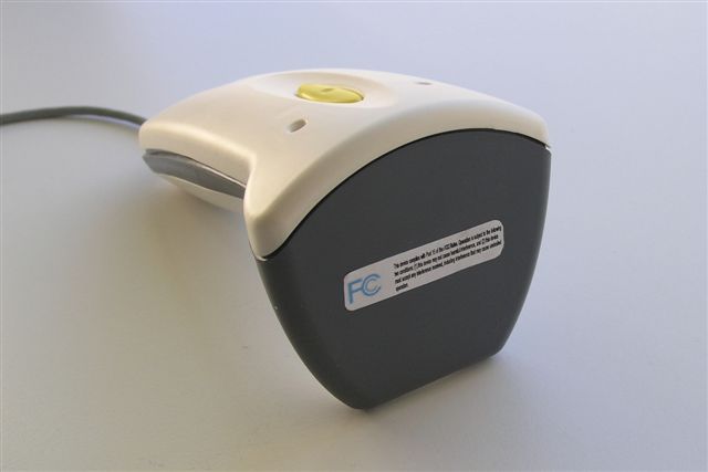
SDH-RIGHTTAGRFID Reader
RightTag Inc.,
Click to zoom
Application Details
- Equipment Class
- DXT - Part 15 Low Power Transceiver, Rx Verified
- Date of Grant
- Nov 22, 2004
- Application Purpose
- Original Equipment
- Date of Application
- Nov 22, 2004
- Equipment Note
- RFID Reader
- Frequency Range
- 13.56000000 - 13.56000000
- Company
- RightTag Inc.,
- Country
- United States
Documents & Files

Document Text
Text extracted from the exhibit documents filed with the FCC. Open a document above to read the original.
Users Manual
User’s Manual 1.General This document describes the installation procedure and usage of the RightTag series 3000 RFID reader. NOTE! This device complies with Part 15 of the FCC Rules. Operation is subject to the following two conditions: (1) this device may not cause harmful interference, and (2) this device must accept any interference received, including interference that may cause undesired operation. This equipment has been tested and found to comply with the limits for a Class B digital device, pursuant to Part 15 of the FCC Rules. These limits are designed to provide reasonable protection against harmful interference in a residential installation. This equipment generates, uses and can radiate radio frequency energy and, if not installed and used in accordance with the instructions, may cause harmful interference to radio communications. However, there is no guarantee that interference will not occur in a particular installation. If this equipment does cause harmful interference to radio or television reception, which can be determined by turning the equipment off and on, the user is encouraged to try to correct the interference by one or more of the following measures: -- Reorient or relocate the receiving antenna. -- Increase the separation between the equipment and receiver. -- Connect the equipment into an outlet on a circuit different from that to which the receiver is connected. -- Consult the dealer or an experienced radio/TV technician for help. 2.Installation Unpack the device. In case you are using the COM version of reader, plug it into a free COM port. The reader is ready for operation. Note: it is essential that your COM port has power supply voltage +5V connected to pin 1 of the connector. The reader gets the power supply via COM cable. In case your COM port does not provide the voltage, it is possible to use a standard adapter that takes the power supply from PS/2 port of your PC. In case you are using the USB version of reader, plug it into a free USB port. The “Found New Hardware” dialog will appear. Below is described install procedure for Windows XP. Note: Installing the reader under Windows 2000 is similar to Windows XP. You have to point to directory with driver file (RFIDReader.ini). Choose “Install from a list or specific location (Advanced)” and click “Next”. Choose “Don’t search. I will choose the driver to install” and click “Next”. Now click “Have Disk...” and select the folder that contains the driver file (RFIDReader.ini). Then click “Next”. Windows XP will then show the next message: Click “Continue Anyway”. This will install the driver. Now click “Finish”. Your computer should now have one more COM port – virtual COM port “RightTag Series 3000 RFID Reader (13.56 MHz)”. Communication between PC and reader can be done now exactly as it would be done through real COM port using the COM reader. 3.Quick start guide If your reader came with special software for PC, start this. If not, you can use any COM port terminal program to read the information from tag. For example: Start -> All Programs -> Accessories -> Communication -> HyperTerminal. Select the COM port your reader is connected to. If using USB reader, the serial port parameters do not matter. If using COM reader, select the baud rate (usually new readers come with 9600bps), 8 data bits, no parity, 1 stop bit, no handshake. Now just put the tag near the reader and press the button on the reader. You should see the tag ID and data written on the tag in the HyperTerminal’s window. Also the reader should make an “OK” beep and blink the green light. If you press the button without putting the tag near the reader’s antenna, you should see red blink and hear “fail” beep. If your reader continuously blinks orange light, it is in continuous read mode – there is no need to press the button, just move the tag near the reader and it will be read. 4.Troubleshooting 1.Problem: Reader seems to do nothing (no sound, no light). Check if the USB or COM cable is connected properly. In case you have the COM version, ensure that there is power supply +5V at pin 1 of COM connector. 2.Problem: Reader always makes the “fail” beep and blinks the red light. Your tag may be of wrong type or damaged. Try to check if the reader was meant for those tags. Also try some more tags. 3.Problem: Reader makes “OK” beep and blinks green light when reading a tag, but nothing appears in the HyperTerminal window. Check, if your reader is connected into the same COM port that you selected when starting HyperTerminal. 4.Problem: Only garbage appears into the HyperTerminal window. Probably the COM port baud rate was wrong. The possible values the reader can be configured: 9600, 19200, 38400, 57600, 115200. Try to change the baud rate.
Cover Letter(s)
DATE: July 21, 2004 Federal Communications Commission 7435 Oakland Mills Road Columbia, MD 21046 Gentlemen: This letter is to comply with Section 0.457(d)(2)(i) pertaining to confidential material. RightTag Inc., would like the following documents regarding this submission for FCC ID: SDH-RightTag to be kept confidential. 1.Doc 6 - Theory of Operaton 2.Doc 7 - Block Diagram 3.Doc 8 – RF_Scanner_BOM 4.Doc 9 - Schematics The above material contains trade secrets or technical data, which would customarily be guarded from competitors. We do not want these documents to be accessible to the general public. Sincerely, Harish Chander President and CEO RightTag Inc., 2048 Lovell Place, Santa Clara, CA 95051 Tel: 408-241-2678 1-800-714-4882 Fax: 1-800-396-0398 Email: [email protected] Website: http://www.righttag.com
External Photos
Bottom of casing removed PCB removed External Photos Top of device Bottom of Device Front of Device Complete Device
Internal Photos
Internal Photos Back of board Front of Board with antenna Attached Front of PCB clarified to view components and writings Top of casing removed Inside top of Casing Bottom of casing removed PCB removed External Photos Top of device Bottom of Device Front of Device Complete Device
Test Report
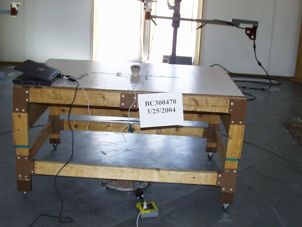
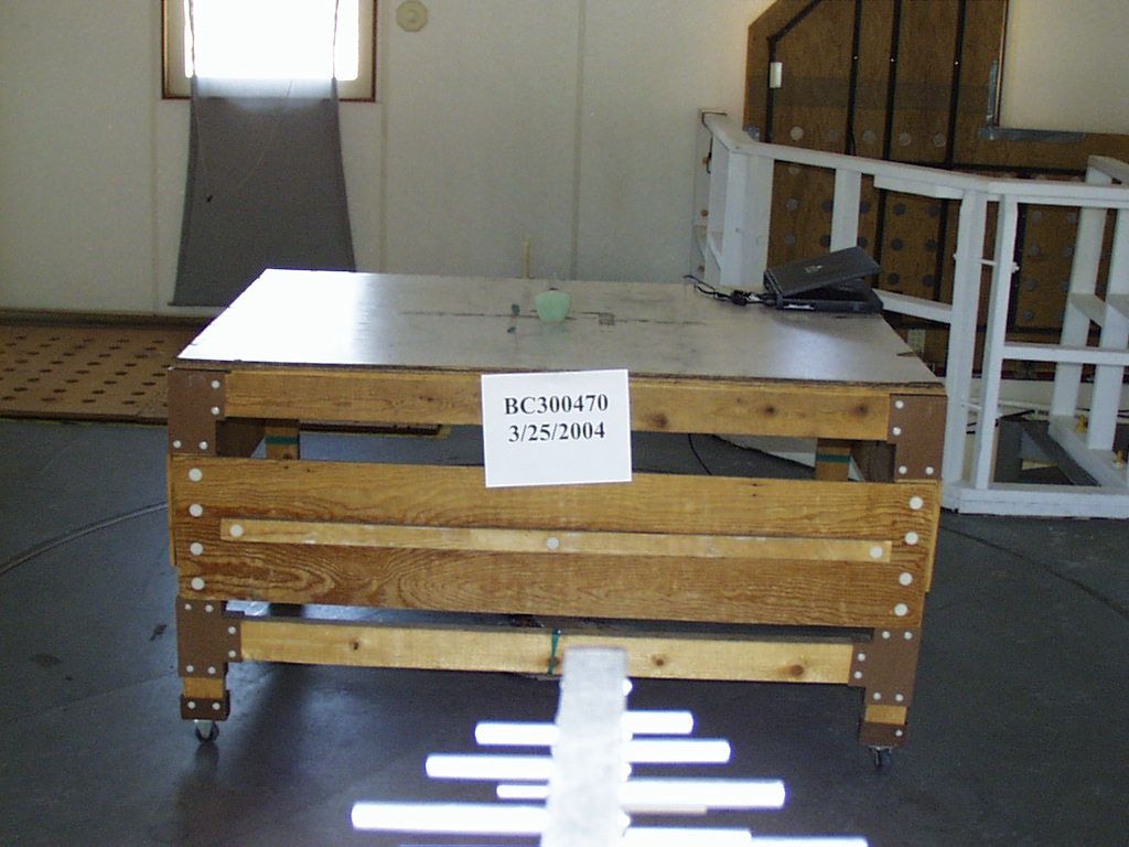
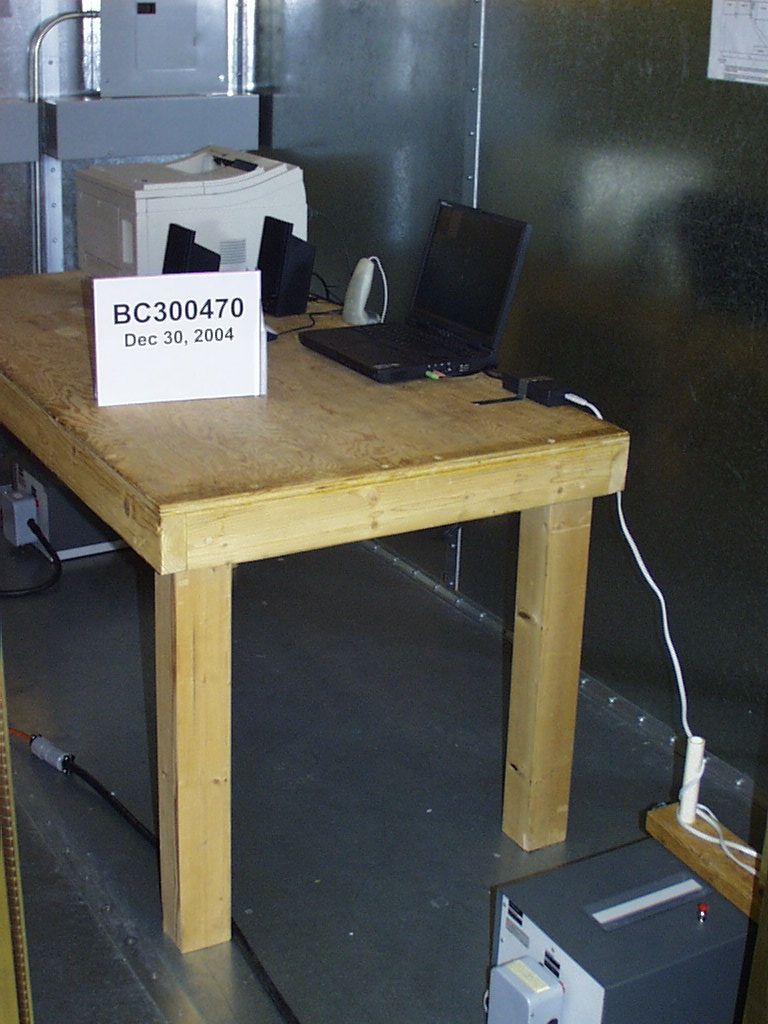
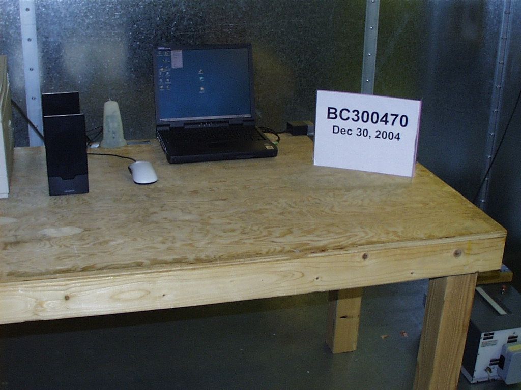
EMC EMISSIONS - TEST REPORT (Full) Test Report No. BC300470 -1 Issue Date: 3-Jan-2005 Model / Serial No. 3000 / 1 Product Type RFID Reader Client Right Tag Manufacturer Right Tag License holder Right Tag 2048 Lovell Place Address Santa Clara, CA 95051 Test Criteria Applied FCC CFR47 Part 15.225 Test Result PASS Test Project Number References BC300470-1 Total Pages Including Appendices: 36 Title 47 CFR 15.225: RADIO FREQUENCY DEVICES operating in the frequency range of 13.553-13.567MHz (including 15.205, 15.207, 15.209 where applicable) Reviewed By : Approved By : INTERNATIONAL APPROVALS LABORATORIES (IAL) reports apply only to the specific samples tested under stated test conditions. It is the manufacturer's responsibility to assure that additional production units of this model are manufactured with identical electrical and mechanical components. IAL have no liability for any deductions, inferences or generalizations drawn by the client or others from IAL issued reports. This report is the confidential property of the client. As a mutual protection to our clients, the public and ourselves, extracts from the test report shall not be reproduced except in full without our written approval of IAL. This report shall not be used by the client to claim product endorsement by NVLAP (No. 200624- 0) or any agency of the US government. International Approval Laboratories and its professional staff hold government and professional organization certifications and are members of IEEE, NVLAP, and VCCI. D I R E C T O R Y Documentation Page(s) Test report 1 - 36 Directory 2 Test Regulations 3 General Remarks 4 - 5 Test-setup Photographs 6 - 10 Appendix A Test Data Sheets and Test Equipment Used 10 - 30 Appendix B Test Plan/Constructional Data Form 31 - 31 Appendix C Measurement Protocol/Test Procedures 32 - 36 STATEMENT OF MEASUREMENT UNCERTAINTY The data and results referenced in this document are true and accurate. The measurement uncertainty for Conducted Emissions in the frequency range of 150kHz – 30MHz is calculated to be ±2.30dB and for Radiated Emissions is calculated to be ±3.60dB in the frequency range of 30MHz – 200MHz and ±3.38dB in the frequency range of 200MHz – 1000MHz. EUT Received Date: 1-July-2004 Testing Start Date: 1-July-2004 Testing End Date: 30-Dec-2004 Project File: BC300470 Page 2 of 36 International Approvals Laboratories, LLC 5541 Central Avenue, Suite 110 Boulder, Colorado 80301 Voice: 303 786 7999 Fax: 303 449 6160 Rev.No 1 Project File: BC400148 Page 3 of 31 International Approvals Laboratories, LLC 5541 Central Avenue, Suite 110 Boulder, Colorado 80301 Voice: 303 786 7999 Fax: 303 449 6160 Rev.No 1 The tests were performed according to following regulations : 1. FCC CFR47 Part 15.205 2. FCC CFR47 Part 15.207 3. FCC CFR47 Part 15.209 4. FCC CFR47 Part 15.231 5. ICES-003 Emission Test Results: Conducted Emissions, Powerline (15.207) - PASS Test Result Minimum limit margin -8.9 dB at 0.212 MHz Maximum limit exceeding dB at MHz Remarks: Powered off PS2 Port of the computer / Measured on AC Mains Radiated Emissions (15.209) / 15.225 (b) - PASS Test Result Minimum limit margin -8.9 dB at 49.01 MHz Maximum limit exceeding dB at MHz Remarks: In Band Radiated Emissions 15.225(a) - PASS Test Result Minimum limit margin -32.6 dB at 13.56 MHz Maximum limit exceeding dB at MHz Remarks: Field measurements in the band of 13.553-13.567 may not exceed 15,848uV/m @ 30m Radiated Emissions 15.255(c) - PASS Test Result Remarks: Devices operated within the frequency band of 13.553-13.567MHz: -20dBc Bandwidth maximum of 0.01% of the center frequency as measured through the temp range of -20 to +50 deg. C, and at 85 - 115% of the nominal supply voltage at 20 deg. C “a new battery would be used in cases where the device is powered from a battery” Radiated Emissions RSS-210 - PASS Test Result Remarks: -20dBc Bandwidth maximum of 0.25% of the center frequency GENERAL REMARKS: The following remarks are to be considered as “where applicable“ and are taken into account while completing any FCC/IC/ETSI radio tests at International Approvals Laboratories, LLC. Testing was performed in 3 different orthogonal axis to determine the worst case emissions from the device. The worst case emissions measurements are shown in this report. FCC CFR47 Part 15.31: Measurement Standards: In any case where the device is powered off a battery, a fresh battery was used during test. In cases where the device is powered off an AC supply, voltage was varied per Part 15.31 to find worst case emissions. FCC CFR47 Part 15.35: Measurement Detector Functions and Bandwidths: FCC Part 15.35 was utilized when performing the measurements within this report. In any case where the device is powered off a battery, a fresh battery was used during test. In cases where the device is powered off an AC supply, voltage was varied per Part 15.31 to find worst case emissions. The actual test distance for the FCC Part 15.209 testing was conducted at 10m for the fact that the device was being tested to EN55022 Class B from 30 MHz to 1000 MHz (meets/exceeds the FCC Part 15.209 & 109B limits) The data is automatically extrapolated back to the FCC 3m limits and measurements are corrected to better show the compliance to FCC requirements and reduce confusion. A correction factor of 10.54dB is used in cases of 30MHz and up for a difference between 10m and 3m measurement distances. All measurements that are lesser than 30MHz where applicable are accompanied with the fall of measurements and calculations to support the interpolation. Support Equipment Description: DELL Laptop Computer / Model: Latitude C600 / Serial: TW-0791UH-12800-0CC-4067, HP LJ4+ printer / Model: C2039A / Serial: JPGF016054, Creative Sound Speakers / Model: SB5270 / Serial: SW00403121001376 Support Equipment was used in order to provide power to the EUT and monitor that the EUT was operational. The actual application of the EUT is to be connected to a POS terminal in a department st…
Text truncated - open the document above for the full version.
Contact Information
Applicant
Harish Chander(President and CEO)
Technical Contact
RightTag Inc.,Harish Chander
408-241-2678
2048 Lovell Place · Santa Clara, California · United States
Non-Technical Contact
RightTag Inc.,Harish Chander
408-241-2678
Test Firm
International Approval Laboratories, LLCTodd Seeley
Technical Specifications
| # | Rule Parts | Frequency Range | Power Output |
|---|---|---|---|
| 1 | 15C | 13.56 MHz - 13.56 MHz | - |