SEOHY-DIS001DISPENSER
HYGINEX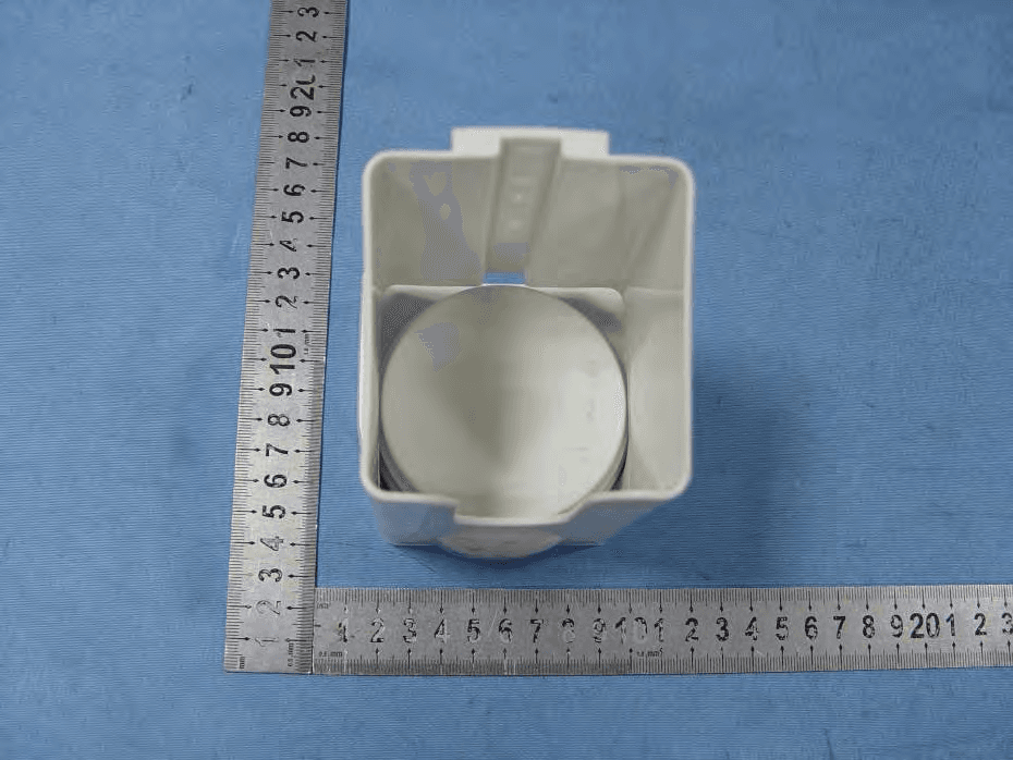
Click to zoom
Application Details
- Equipment Class
- DXX - Part 15 Low Power Communication Device Transmitter
- Date of Grant
- Apr 21, 2013
- Application Purpose
- Original Equipment
- Date of Application
- Apr 21, 2013
- Equipment Note
- DISPENSER
- Frequency Range
- 2412.00000000 - 2480.00000000
- Company
- HYGINEX
- Country
- Israel
Documents & Files
Document Text
Text extracted from the exhibit documents filed with the FCC. Open a document above to read the original.
Users Manual
Installation & Maintenance Manual Version 1.0 © 2012 Hyginex Ltd. All rights reserved. This document is the protected intellectual property of Hyginex Ltd. Any copying, reprinting, reuse, reproduction ,adaptation distribution or translation without the prior written permission of Hyginex Ltd. is prohibited. The information included in this document is subject to change without notice. For more information, please contact: Hyginex LTD 18 Shenkar St, Heezliya, Israel 46725 Telephone: +972-77-4507088 Fax: +972-97-746068 Email: [email protected] H y g i n e x Table of Contents 1 OVERVIEW ............................................................................ 5 1.1 ABOUT THIS MANUAL......................................................... 6 2 INSTALLATION ...................................................................... 6 2.1 DISPENSER ....................................................................... 7 2.1.1 Selecting a Mounting Location for a Dispenser .......... 7 2.1.2 Installing the Dispenser ............................................. 7 2.1.3 Dispenser Recognition Testing ................................ 11 2.1.4 Documenting a Dispenser installation ..................... 11 2.2 CHARGING STATION ......................................................... 12 2.2.1 Selecting a Location for a Charge Station ................ 12 2.2.2 Installing a Charging Station ................................... 12 2.2.3 Testing a Charge Station ......................................... 13 2.2.4 Documenting a Charging Station Installation .......... 13 2.3 BRACELET ...................................................................... 14 2.3.1 Wearing a Bracelet ................................................. 14 2.3.2 Bracelet Recognition Testing ................................... 14 2.3.3 Documenting a Bracelet Designation ...................... 15 2.4 LOCATION BEACONS......................................................... 15 2.4.1 Selecting a Location for a Bedside/Corridor Beacon . 15 2.4.2 Installing a Location Beacon ................................... 20 2.4.3 Testing a Beacon .................................................... 24 2.4.4 Documenting a Beacon Installation ......................... 26 2.5 HYGINEX LOCAL COMPUTER ............................................... 26 3 TEST THE SYSTEM - WALK TEST ........................................... 26 4 MAINTENANCE ................................................................... 27 4.1 REPLACING THE BATTERY ................................................... 27 4.2 UPDATING THE INSTALLATION PROJECT SPREADSHEET .............. 27 Hyginex Installation & Maintenance Manual 4 H y g i n e x 5 CONTACT INFORMATION ................................................... 28 Installation & Maintenance Manual 5 H y g i n e x 1 Overview Hyginex hand hygiene control solutions provide a simple and effective solution for monitoring and assisting healthcare workers’ hand hygiene compliance in an unobtrusive manner and with almost no management effort. The Hyginex system includes the following components: Beacon: A battery operated wireless passive radio frequency (RF) transmitter. Dispenser: A soap and hand sanitizer delivery device that includes sensors and transmitters. Bracelet: Interacts via wireless connection with beacon and dispenser sensors to detect proper hand washing and hand hygiene habits. It also reminds staff to wash hands according to hospital protocol. And finally, the Bracelet transfers hand hygiene data to the Hyginex server via the Dongle. Chargers for the bracelets are included with the system purchase. Dongle: Connects to a hospital ward’s computer via USB port. The dongle downloads the data from the various bracelets in the Hyginex system via wireless connection. Server: Collects the data from the hospital computer and automatically analyzes it. Report generator: Produces detailed hygiene compliance reports. The scope of a report can cover an individual staff member or all staff members assigned a bracelet. The scope of a report and frequency is determined by the hospital during the purchasing process. Hyginex Installation & Maintenance Manual 6 H y g i n e x 1.1 About this Manual This manual is for the Hyginex agent. The agent is expected to have knowledge of the Hyginex system operation and basic construction methods. The manual covers the installation procedure for each hardware component type in the system. 2 Installation Each component in the system arrives on site preprogrammed. In case custom programming is required, contact Hyginex for programming tools and instructions. This means that the Beacons, dispensers and server are already aware of the bracelets. Each bracelet is assigned to a staff member by the Hyginex agent performing the installation. The Hyginex system components require the following batteries: Beacon: Six 1.5V D size alkaline batteries Dispenser: Three 1.5V AA size alkaline batteries 7 Installation H y g i n e x Bracelet: One 3.6V Lithium Polymer 120mAh battery (installed during bracelet setup) Always use new batteries do not mix old and new batteries. This will limit the number of maintenance calls while the system is online. Each Hyginex agent is supplied with a test bracelet. This bracelet is for testing the installation exclusively. The testing bracelet may be identified by its serial number visible on the face of the bracelet. The serial number is zero. 2.1 Dispenser The Hyginex Dispenser should be the only type of dispenser on site. All dispensers that are not Hyginex Dispenser should be removed from the ward or area where Hyginex devices will be used. This is necessary because non-logged hand wash events will compromise hygiene data integrity. 2.1.1 Selecting a Mounting Location for a Dispenser The dispenser can be mounted on a flat wall, next to a sink or entry way. Alternatively, a dispenser can be hung off a bracket from the footboard of a bed or the side of a medication cart. Note: Avoi…
Text truncated - open the document above for the full version.
Cover Letter(s)
HYGINEX Jan 30, 2013 To: SIEMIC, INC. 775 Montague Expressway Milpitas, CA 95035 USA Dear Sir/Madam, Re: Project and Product Certification Representative Authorization Letter We, ______HYGINEX ___hereby authorize SIEMIC, INC. to act as a Certification Body for certifying for the following project(s): FCC ID: SEOHY-DIS001 Product Description: DISPENSER Model name: DIS-000-01 We affirm that between SIEMIC and _ HYGINEX __, any difference in understanding, including test plan, measurement methods, applicable standards and relevant procedures and processes have been resolved prior to commencement of testing activities. Sincerely, Client’s signature : Client’s name / title : Efrat Raichman / CEO Contact information / address : 18 Shenkar St.., First Floor, P.O. Box 12317, HERZLIYA, Israel
Cover Letter(s)
SCS-F19: Confidentiality Request Letter Page 1 of 2 Rev 3.0 775 Montague Expressway Milpitas, CA 95035 Tel: 408-526-1188 Fax: 408-526-1088 Email: [email protected] Confidentiality Request Letter Revision History Reason for Amendment (current / obsolete) From To Approved Date Initial Release (obsolete) 1.0 1.0 Nov-14-2006 Adding CFR 2.459 (obsolete) 1.0 2.0 August – 11 - 2008 Updated company template & Added text box (current) 2.0 3.0 Jan-31-2012 SCS-F19: Confidentiality Request Letter Page 2 of 2 Rev 3.0 HYGINEX Jan 30, 2012 To: Federal Communications Commission Authorization and Evaluation Division 7435 Oakland Mills Road Columbia, MD Subject: Permanent Confidentiality Request for FCC ID: SEOHY-DIS001 We hereby request confidential treatment of information accompanying this application as outlined below: - Block Diagram - Schematics - Operational Description The above materials contain trade secrets and proprietary information not customarily released to the public. The public disclosure of these materials may be harmful to the applicant and provide unjustified benefits to its competitors. The applicant understands that pursuant to Section 0.457 & 0.459 of the Rules, disclosure of this application and all accompanying documentation will not be made before the date of the Grant for this application.
Internal Photos
Antenna
Test Report
Page 1 of 51 FCC ID: SEOHY-DIS001 ACCURATE TECHNOLOGY CO. LTD REPORT NO. ATE20122105 FCC CERTIFICATION On Behalf of HYGINEX DISPENSER Model No.: DIS-000-01 FCC ID: SEOHY-DIS001 Prepared for : HYGINEX Address : 18 shenkar St., First Floor, P.O. Box 12317, HERZLIYA Prepared by : ACCURATE TECHNOLOGY CO. LTD Address : F1, Bldg. A, Changyuan New Material Port, Keyuan Rd. Science & Industry Park, Nanshan, Shenzhen, Guangdong P.R. China Tel: (0755) 26503290 Fax: (0755) 26503396 Report Number : ATE20122105 Date of Test : Feb 15 , 2013 Date of Report : Feb 16 , 2013 Page 2 of 51 FCC ID: SEOHY-DIS001 ACCURATE TECHNOLOGY CO. LTD REPORT NO. ATE20122105 TABLE OF CONTENTS Description Page Test Report Certification 1. GENERAL INFORMATION .......................................................................................................... 4 1.1. Description of Device (EUT)....................................................................................................................4 1.2. Description of Test Facility ......................................................................................................................4 1.3. Measurement Uncertainty.........................................................................................................................5 2. MEASURING DEVICE AND TEST EQUIPMENT ..................................................................... 6 3. SUMMARY OF TEST RESULTS................................................................................................... 7 4. FUNDAMENTAL AND HARMONICS RADIATED EMISSION FOR SECTION 15.249(A) 8 4.1. Block Diagram of Test Setup....................................................................................................................8 4.2. The Emission Limit ..................................................................................................................................9 4.3. Configuration of EUT on Measurement ...................................................................................................9 4.4. Operating Condition of EUT ....................................................................................................................9 4.5. Test Procedure ........................................................................................................................................10 4.6. The Field Strength of Radiation Emission Measurement Results ..........................................................11 5. SPURIOUS RADIATED EMISSION FOR SECTION 15.249(D) ............................................. 14 5.1. Block Diagram of Test Setup..................................................................................................................14 5.2. The Emission Limit For Section 15.249(d) ............................................................................................15 5.3. EUT Configuration on Measurement .....................................................................................................15 5.4. Operating Condition of EUT ..................................................................................................................15 5.5. Test Procedure ........................................................................................................................................16 5.6. The Emission Measurement Result ........................................................................................................17 6. BAND EDGES ................................................................................................................................. 20 6.1. The Requirement ....................................................................................................................................20 6.2. EUT Configuration on Measurement .....................................................................................................20 6.3. Operating Condition of EUT ..................................................................................................................20 6.4. Test Procedure ........................................................................................................................................20 6.5. The Measurement Result ........................................................................................................................21 7. 20DB BANDWIDTH....................................................................................................................... 23 7.1. Block Diagram of Test Setup..................................................................................................................23 7.2. EUT Configuration on Measurement .....................................................................................................23 7.3. Operating Condition of EUT ..................................................................................................................23 7.4. Test Procedure ........................................................................................................................................24 7.5. Test Result ..............................................................................................................................................24 8. ANTENNA REQUIREMENT........................................................................................................ 25 8.1. The Requirement ....................................................................................................................................25 8.2. Antenna Construction .............................................................................................................................25 APPENDIX I ( TEST CURVES) (28 pages) Page 3 of 51 FCC ID: SEOHY-DIS001 ACCURATE TECHNOLOGY CO. LTD REPORT NO. ATE20122105 Test Report Certification Applicant : HYGINEX Manufacturer : Exploit Innovation Limited EUT Description : DISPENSER (A) MODEL NO.: DIS-000-01 (B) Trade Name.…
Text truncated - open the document above for the full version.
Test Setup Photos
Radiated spurious emission (up to 1G): Radiated spurious emission (above 1G):
Contact Information
Applicant
Efrat Raichman(CEO)
Test Firm
Accurate Technology Co., Ltd.Sean Liu
Technical Specifications
| # | Rule Parts | Frequency Range | Power Output |
|---|---|---|---|
| 1 | 15C | 2.41 GHz - 2.48 GHz | - |
Other Applications from HYGINEX

SEOHY-PIR001
May 27, 2013BEACON
Equipment Class
DXX - Part 15 Low Power Communication Device Transmitter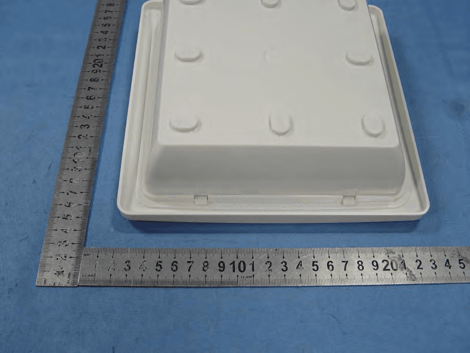
SEOHY-BEC001
Apr 16, 2013BEACON
Equipment Class
DXX - Part 15 Low Power Communication Device Transmitter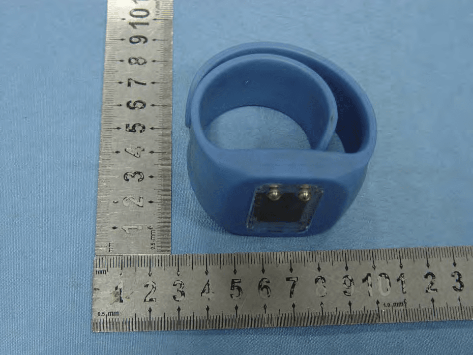
SEOHY-BRC003
Apr 16, 2013BRACELET
Equipment Class
DXX - Part 15 Low Power Communication Device Transmitter