SEVGRC20GARemote Control Transmitter
Gooding Enterprise Co., Ltd.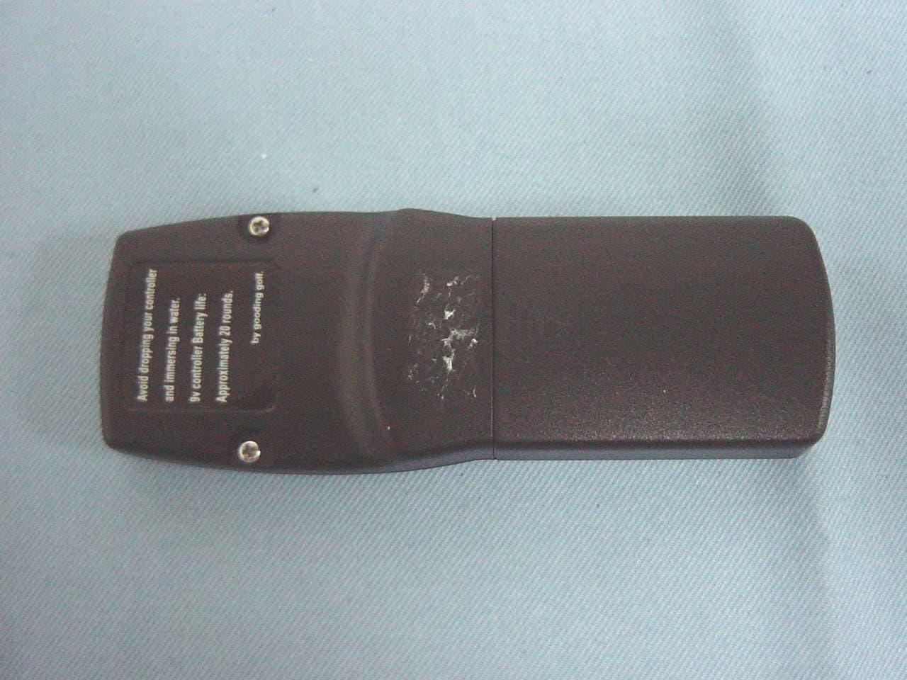
Click to zoom
Application Details
- Equipment Class
- DSC - Part 15 Security/Remote Control Transmitter
- Date of Grant
- Sep 01, 2004
- Application Purpose
- Original Equipment
- Date of Application
- Sep 01, 2004
- Equipment Note
- Remote Control Transmitter
- Frequency Range
- 433.92000000 - 433.92000000
- Company
- Gooding Enterprise Co., Ltd.
- Country
- Taiwan
Documents & Files
Document Text
Text extracted from the exhibit documents filed with the FCC. Open a document above to read the original.
Users Manual
1 MANUAL Index 1. Productions contents 2. Productions specifications 3. Safety rules 4. Operation 5. Battery care and maintenance 6. Battery charging operation 7. Trouble-shooting 8. Warranty Card Productions contents 1. Gorgeous GRC-300 2. Battery 24 V 3. Battery charger 4. Remote controller 5. Cable controller 6. Manual and Warranty Card Gorgeous structural drawing 1.Cart frame 2.Main control box 3.Drive system 4.Front wheel 5.rear wheel 6. battery-serving tray 7.Direction server 8.Cart bag Neck bottom support 9. Cart bag bottom support 2 Product Specifications 1. (Weight) 12.5KG Battery 24V.20ma. Battery charger Model:CU-090 INTELLIGENT AUTO-DETECTING CHARGER Frame 6061-T5 Aluminum Motor 24V DC motor. Remote Control FM Transmitter Control Electronics FM receiver with microprocessor control sets for Speed ,direction, range tether and over-current Protection. Measurement 28〞/ 16〞/ 16〞 Safety rules 2. Normal operation: Please read and understand all instructions in the manual before operate。 1. Never allow child under 12 years old to operate cart without adult accompany。 2. Please store remote controller in the secure place to prevent child catch。 3. Never carry passengers and goods except golf cart-bag。 4. Dangerous Condition:please operate cart with one hand on handle and slow down 。 1.Steep slope. 2.Congested area. 3.Narrow cart path. 6.Do not operate at long range out of your vision 。 7.Avoid dropping your remote controller。 8.Avoid operate cart in the rain。 9.When any emergency happen ,please stop the cart。 10.Read and follow all instructions for safe use and charging. 11.Please use original indicate battery and charger,to keep the cart in good condition 。 3 OPERATION Step #1. Swing Cart bag- bottom support forward. Step #2. Release front wheel bolt and Swing wheels turn to locked position(1) Step #3.Unfold and fix frame Upright rear frame and tighten quick release (1). Adjust handle frame and tighten quick release(2). (1) (2) (1) 4 Step #4.Install battery Set battery lay on the battery-serving tray. Battery-bag with Gorgeous markings facing up. Strap battery into battery serving tray . Step #5 Connect battery and control electronics Connect battery cable with control electronics(1). Step #6 Installing golf-cart bag Put cart bag on neck bottom support Make sure secure with neck support straps. (1) 5 Main Control Box (1)POWER BUTTON ON . OFF 1. Please press ON button to start power. 2.Please press OFF button to stop power. (2)BATTERY LEVEL INDICATION When power on,battery level lamps will show the battery level , When green lamp light that show the battery is full, you can play 18 holes. When yellow lamp light that show the battery is half, you can play 9 holes. When red lam light that show the battery is low, need to be recharged. 。 (3)DIRECTION LEVEL INDICATION Direction lamps will light to show the direction ,include forward ,backward ,left ,and right ,when main control box receive the command from the remote controller 。 (4)RESET BOTTON Gorgeous’ main control box contain an over-current circuit , the circuit will terminate the power to main control box when the current occur an overload ,then press reset button that main control box will return to the normal state. 6 REMOTE CONTROLLER A. Direction button B. Speed control button C. Flashing light 1. Press ↑ button to go forward motion、press button again to stop Gorgeous 。 2. Press ↓ button to move backward、press button again to stop Gorgeous 。 3. Press→button to turn right ,then release to go straight。 4. Press←button to turn left ,then release to go straight。 5. Use speed + button to increase speed,8 speed steps control。 6. Use speed - button to decrease speed,8 speed steps control。 7. ≡ is flashing light,remote controller ON is indicated by flashing light。 8. Remote controller battery、9v already installed,replace the battery in the controller approx 20 rounds。 9. Avoid dropping your controller and immerse in water。 10. Never use remote controller and cable controller at the same time。 7 Cable Controller A. Direction button. 1. Please use cable-controller to instead remote controller when controller didn’t work normal。 2. Put the Cable controller’s PS2 connector into the socket on the main control box。 3. Press ↑ button to go forward motion、press button again to stop Gorgeous。 4. Press ↓ button to move backward、press button again to stop Gorgeous。 5. Press→button to turn right ,then release to go straight。 8 Battery Care and Maintenance Description Gorgeous power is provide by Long sealed lead acid battery. Model# WP20-24E. 24Vdt20Ah Before use battery 1. Battery should be full charged more than 4 hours at the first time and store it for a long time。 2. Make sure battery terminals bolts are tightened securely。 3. Avoid put anything on battery upside。 4. Please open the battery bag zipper;before recharge. 5. Never let battery stand upside down in any condition。 stand up(○) lie down(△) sideways(△) upside down(╳) Feature 1. For good performance and long life exercise,battery must be full charged each use。 2. You can use Gorgeous to play 18 holes when battery is full;after 18 holes ,you want to play 9 holes more, please check battery level indication。 3. A second battery is recommended if you want to use Gorgeous for more than 36 holes in one day。 4. Store Battery should be recharged at least every three months。 5. Battery life:normal use:1∼3years Circle use: 300 times 9 Maintenance z STORE BATTERY TEMPERATURE: -20°C ~ 40°C,WETNESS RANGRE: 25%-85%。 z PLEASE STORE BATTERY AFTER FULL RECHARGED,OTHERWISE BATTERY LIFE WILL BE SHORTENED。 z BATTER IS STORED FOR A LONG TIME WILL CAUSE CAPACITY LOSE。 z STORE TEEMPERATURE SUGEESTION AND RECHARGE CIRCLE: 20°C(68°F) UNDER:9 MONTHS 20°C~30°C(68°F-86°F):6 MONTHS 30°C(86°F)UP:3MONTHS BAD BATTERY JUDGE AND RECOVER z Measure method for judge battery from good or bad as follows ;Initial voltage、 resistance、current capacity、 check the variation when batter is charging。 z The initial voltage of a newes…
Text truncated - open the document above for the full version.
Block Diagram
Battery Power Switch EEPROM RF Transmitter CPU Block Diagram
Cover Letter(s)
GOODING ENTERPREISE CO., LTD. Power of Attorney Date: August 4, 2004 We, the undersigned, hereby authorize Compliance Certification Services Inc. to act on our behalf in all matters relating to all processes related to FCC applications and communications issue. Any and all acts carried out by Compliance Certification Services Inc. on our behalf shall have the same effects as acts of our own. If you have any questions regarding this authorization, please don’t hesitate to contact us. Thank you. Sincerely yours, ----------------------------------------------------- SALES MANAGER GOODING ENTERPREISE CO., LTD.
Cover Letter(s)
Mike Kuo From: [email protected] on behalf of [email protected] Sent: September02 2004 Thursday 2:34 AM To: Mike Kuo Cc: CCS- Application (E-mail) Subject: Gooding Enterprise Co., Ltd., FCC ID: SEVGRC20GA, Assessment NO. : AN04T4119, Notice#1 9/2/2004 Hi Mike, Please refer to the following for our replies. Best regards, Ting Question#1:Section 7.1 of test report, 20dB bandwidth test plot indicated Channel Frequency 393.444 MHz but certer frequency was set at 433.92MHz. Please explain. Ans #1: Please refer to the attached for revised test report. Question#2: Please explain how this device complies with 15.231(a)(1) (2) and please provide strong technical description to show that this device comply with periodical transmission definition. Ans #2: Please refer to the attached for revised test report. Question#3: The limits of radiated emission of fundamental is not correct, please revise. Ans #3: Please refer to the attached for revised test report. Best Regards Mike Kuo Compliance Certification Services 561F Monterey Road Morgan Hill CA 95037 Tel: (408)463-0885 x: 105 Fax: (408)463-0888 http://www.ccsemc.com Mike Kuo <[email protected]> 2004/08/27 08:58 AM "CCS- Application (E-mail)" <[email protected]>
External Photos
Compliance Certification Services Inc. Report No: B31018201 Date of Issue: December 1, 2003 Page 1 of 5 EXTERNAL PHOTOGRPHS OF EUT Compliance Certification Services Inc. Report No: B31018201 Date of Issue: December 1, 2003 Page 2 Compliance Certification Services Inc. Report No: B31018201 Date of Issue: December 1, 2003 Page 3
ID Label/Location Info
FCC ID / IC LABEL FORMAT AND LOCATION Applicant: Gooding Enterprise Co., Ltd. FCC ID: SEVGRC20GA Gooding Enterprise Co., Ltd. Golf Remote Control Cart Model: GRC-300 FCC ID: SEVGRC20GA
Internal Photos
Compliance Certification Services Inc. Report No: B31018201 Date of Issue: December 1, 2003 Page 4 INTERNAL PHOTOGRPHS OF EUT Compliance Certification Services Inc. Report No: B31018201 Date of Issue: December 1, 2003 Page 5
Operational Description
Operation Description 1. Press the switch to start the power for CPU, RF transmitter and EEPROM. 2. Accept the switch signal, the CPU will setup a RF transmitter to keep the power continuously. 3. Accept the switch signal, the CPU will release "STOP" code to shut down the power from RF transmitter.
Schematics
1 2 3 4 56 ABCD 6 5 4 3 2 1 D CBA Title Number Revision Size B Date: 30-Apr-2004 Sheet of File: D:\product\TEST1.Ddb Drawn By: R447K Q2A1048 R347K B123A VDD 1 VSS 14 RC2 8 RC3 7 RC4 6 RC5/T0 5 RB0 13 RB1 12 RB2 11 RB3/MCR 4 RB4/OSO 3 RB5/OSI 2 RC0 10 RC1 9 U1PIC16C505 CS 1 CLK 2 DI 3 DO 4 GND 5 NC 6 NC 7 VCC 8 U293C46 VCC C2104 L12.2UH C31000P C410P Q1H-10 R547K R6 2.2K LED1RED RFOUT R847K 12345 A1CON5 VCC RFOUT SW66*6*5SW56*6*5SW36*6*5SW46*6*5SW16*3.5*5 R13 47K RLF RRFGOBK SP- R947K Q3C2712 R14.7K PWO RLF RRF GOBKSP+ PWO Z15.1V R7560 VCC C1104 SW26*3.5*5 R11 47K SP+ SP- R14 47K R247K R10 47K R12 47K C5104 R15110 C63P X1434M R1662K SW76*3.5*5SW86*3.5*5 D1 1N4148 D2 1N4148 D3 1N4148 D4 1N4148 D5 1N4148 D6 1N4148 BKGOSP-BKGOSP+ C73P RLFSP+RRFBKSP-GO 1 2 3 4 56 ABCD 6 5 4 3 2 1 D CBA Title Number Revision Size B Date: 30-Apr-2004 Sheet of File: D:\product\TEST1.Ddb Drawn By: R447K Q2A1048 R347K B123A VDD 1 VSS 14 RC2 8 RC3 7 RC4 6 RC5/T0 5 RB0 13 RB1 12 RB2 11 RB3/MCR 4 RB4/OSO 3 RB5/OSI 2 RC0 10 RC1 9 U1PIC16C505 CS 1 CLK 2 DI 3 DO 4 GND 5 NC 6 NC 7 VCC 8 U293C46 VCC C2104 L12.2UH C4* Q1H-10 R520K R6 2.2K LED1RED RFOUT R847K 12345 A1CON5 VCC RFOUT SW66*6*5SW56*6*5SW36*6*5SW46*6*5SW16*3.5*5 R13 47K RLF RRFGOBK SP- R947K Q3C2712 R14.7K PWO RLF RRF GOBKSP+ PWO Z15.1V R7560 VCC C1104 SW26*3.5*5 R11 47K SP+ SP- R14 47K R247K R10 47K R12 47K C5104 R150 C63P R1627K SW76*3.5*5SW86*3.5*5 D1 1N4148 D2 1N4148 D3 1N4148 D4 1N4148 D5 1N4148 D6 1N4148 BKGOSP-BKGOSP+ C72P RLFSP+RRFBKSP-GO VC1 7P
Test Report
Compliance Certification Services Inc. Date of Issue: December 1, 2003 Report No: B31018201-RP FCC ID: SEVGRC20GA Note: This report shall not be reproduced except in full, without the written approval of Compliance Certification Services Inc. This document may be altered or revised by Compliance Certification Services Inc. personnel only, and shall be noted in the revision section of the document. Page 1 of 28 FCC 47 CFR PART 15 SUBPART C TEST REPORT For Gooding Enterprise Co., Ltd. Golf Remote Control Cart Model: GRC-300 Trade Name: GORGEOUS Prepared for Gooding Enterprise Co., Ltd. No. 30-3, 31st Rd., Taichung Industry Zone, Taichung, Taiwan, R.O.C. Prepared by Compliance Certification Services Inc. No. 81-1, Lane 210, Bade Rd. 2, Luchu Hsiang, Taoyuan Hsien, (338) Taiwan, R.O.C. TEL: 886-3-324-0332 FAX: 886-3-324-5235 Compliance Certification Services Inc. Date of Issue: December 1, 2003 Report No: B31018201-RP FCC ID: SEVGRC20GA Page 2 TABLE OF CONTENTS 1. TEST RESULT CERTIFICATION............................................................................................. 3 2. EUT DESCRIPTION .................................................................................................................... 4 3. TEST METHODOLOGY ............................................................................................................. 5 3.1 EUT CONFIGURATION.............................................................................................................. 5 3.2 EUT EXERCISE......................................................................................................................... 5 3.3 GENERAL TEST PROCEDURES.................................................................................................. 5 3.4 FCC PART 15.205 RESTRICTED BANDS OF OPERATIONS ............................................. 6 3.5 DESCRIPTION OF TEST MODES................................................................................................. 6 4. INSTRUMENT CALIBRATION................................................................................................. 7 5. FACILITIES AND ACCREDITATIONS ................................................................................... 8 5.1 FACILITIES.............................................................................................................................. 8 5.2 EQUIPMENT............................................................................................................................. 8 5.3 LABORATORY ACCREDITATIONS AND LISTING....................................................................... 8 5.4 TABLE OF ACCREDITATIONS AND LISTINGS............................................................................ 9 6. SETUP OF EQUIPMENT UNDER TEST ................................................................................ 10 6.1 SETUP CONFIGURATION OF EUT............................................................................................ 10 6.2 SUPPORT EQUIPMENT............................................................................................................ 10 7. FCC PART 15.231 REQUIREMENTS...................................................................................... 11 7.1 20 DB BANDWIDTH.......................................................................................................... 11 7.2 LIMIT OF TRANSMISSION TIME.............................................................................................. 13 7.3 DUTY CYCLE..................................................................................................................... 15 7.4 RADIATED EMISSIONS........................................................................................................... 18 7.5 POWERLINE CONDUCTED EMISSIONS.................................................................................... 27 Compliance Certification Services Inc. Date of Issue: December 1, 2003 Report No: B31018201-RP FCC ID: SEVGRC20GA Page 4 2. EUT DESCRIPTION Product Golf Remote Control Cart Trade Name GORGEOUS Model Number GRC-300 Model Difference N/A Power Supply Powered by battery (Rating: 9Vdc) Frequency Range 433.92 MHz Modulation Technique Pulse Modulation Antenna Designation Printed Antenna Note: This submittal(s) (test report) is intended for FCC ID: SEVGRC20GA filing to comply with Section 15.207, 15.209 and 15.231 of the FCC Part 15, Subpart C Rules. Compliance Certification Services Inc. Date of Issue: December 1, 2003 Report No: B31018201-RP FCC ID: SEVGRC20GA Page 5 3. TEST METHODOLOGY The tests documented in this report were performed in accordance with ANSI C63.4 (2001) and FCC CFR 47 2.1046, 2.1047, 2.1049, 2.1051, 2.1053, 2.1055, 2.1057, 15.207, 15.209 and 15.231. 3.1 EUT CONFIGURATION The EUT configuration for testing is installed on RF field strength measurement to meet the Commissions requirement and operating in a manner that intends to maximize its emission characteristics in a continuous normal application. 3.2 EUT EXERCISE The EUT was operated in the engineering mode to fix the TX frequency that was for the purpose of the measurements. 3.3 GENERAL TEST PROCEDURES Conducted Emissions The EUT is placed on the turntable, which is 0.8 m above ground plane. According to the requirements in Section 13.1.4.1 of ANSI C63.4 (2001).Conducted emissions from the EUT measured in the frequency range between 0.15 MHz and 30MHz using CISPR Quasi-peak and average detector modes. Radiated Emissions The EUT is placed on a turn table, which is 0.8 m above ground plane. The turntable shall rotate 360 degrees to determine the position of maximum emission level. EUT is set 3m away from the receiving antenna, which varied from 1m to 4m to find out the highest emission. And also, each emission was to be maximized by changing the polarization of receiving antenna both horizontal and vertical. In order to find out the max. emission, the relative positions of this hand-held transmitte…
Text truncated - open the document above for the full version.
Test Setup Photos
Compliance Certification Services Inc. Report No: B31018201-RP FCC ID: SEVGRC20GA Date of Issue: December 1, 2003 Page 26 APPENDIX 1 PHOTOGRPHS OF TEST SETUP Radiated Emission Set up Photos
Contact Information
Applicant
Sunny Lin(Sales manager)
Test Firm
Compliance Certification Services Inc.Tony Houng
Technical Specifications
| # | Rule Parts | Frequency Range | Power Output |
|---|---|---|---|
| 1 | 15.231 | 433.92 MHz - 433.92 MHz | - |