SFEEVR25WIRELESS VACUUM SENSOR
InnovAg Pty Ltd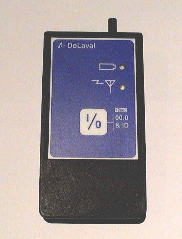
Click to zoom
Application Details
- Equipment Class
- DXT - Part 15 Low Power Transceiver, Rx Verified
- Date of Grant
- Sep 23, 2004
- Application Purpose
- Original Equipment
- Date of Application
- Aug 11, 2004
- Equipment Note
- WIRELESS VACUUM SENSOR
- Frequency Range
- 902.00000000 - 928.00000000
- Company
- InnovAg Pty Ltd
- Country
- Australia
Documents & Files
Document Text
Text extracted from the exhibit documents filed with the FCC. Open a document above to read the original.
Users Manual
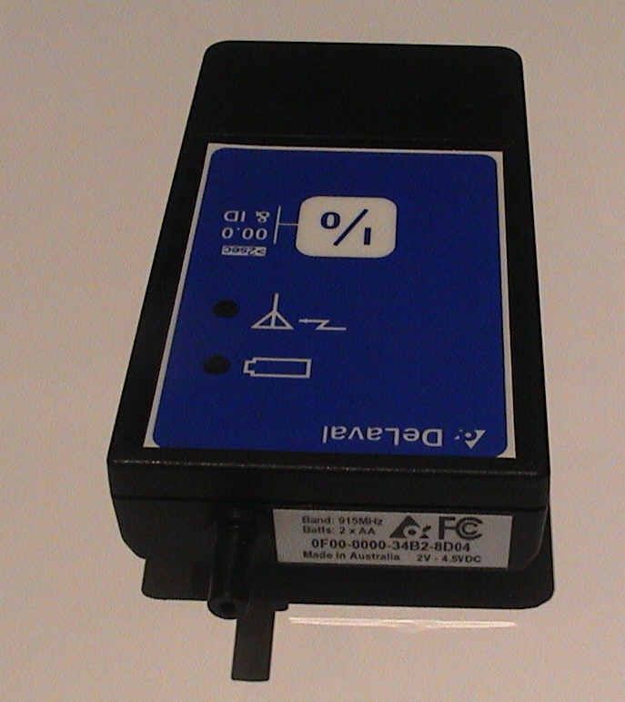
Creative Product Design 82 Victoria Street, Sandringham 3191 Victoria Australia Int’l +61 3 9521 9383 Toll free 1 800 061 167 Fax +61 3 9521 8009 A.C.N. 050 028 423 1 Our Ref. DR51-0033-01 4 June 2003 VPR100 Wireless Vacuum Sensor Operating Instructions. This document is for use in field trials of the Sensors and as a basis for a formal user manual. It is not intended for use by the general public or to be supplied with production units. In particular error and calibration information should only be made available to DeLaval staff. Controls and Indicators. The Sensor has only a single button and two LEDs for status indication. Detailed status information is displayed on the VPR100 Sensor Status screen. I 0 00.0 & ID >2sec Battery Level LED Wireless Activity LED Power On/Off Button The button is used to turn the sensor on/off and initiate various special functions by holding the button down. The Battery LED normally shows the state of the batteries, but also shows special status indications in conjunction with the other LED. The Wireless LED flashes when information is being received from the VPR100. It is primarily used to show that the Sensor is within range of the VPR100 and reception is not being blocked by metal objects nearby. Turning the Sensor On. 1. Make sure fresh batteries are installed. It requires two ‘AA’ cells which can be normal 1.5V Alkaline or 1.2V NiCd/NiMH rechargables. DO NOT use 3V Lithium cells or mix different types in the same Sensor. 2. Press the button to turn the unit on. The Battery LED will give a long blink on startup (Green for 868MHz European units, Orange for 915MHz Nth/Sth American, Australian and NZ units), after which it should give a short blink every 2 seconds if the battery level is good. Registering the Sensor on the VPR100. Before the Sensor can be used it must be ‘registered’ on the VPR100. Registration is only done once when a new sensor is being used for the first time. Up to 9 sensors can be registered, but at this point only the first two are used. Readings from the first two sensors in the list are shown as “Ext 1” and “Ext 2” in Airflow and Vacuum Modes. 1. Turn on the VPR100 and select Setup - Sensor Setup . 2. With the Sensor turned on, press and hold the button until the Battery LED shows Orange. 3. The VPR100 should beep and the sensor will appear on the screen with its type and ESN. A tick should be shown in the box on the left-hand side. The Wireless LED should be blink Red showing the Sensor is communicating with the VPR100. 4. The Sensor Information icon should appear . Press it and a pop-up window shows status information about the Sensor such as Battery Voltage, software version, sensor temperature, etc. 5. Press the Info icon again to remove the window. It will also automatically clear after a few seconds. 6. Exit the Sensor Setup screen and the sensor will be saved into VPR100 memory. Using the Sensor. The sensors can be used in the VPR100’s Vacuum and Airflow Modes only. 1. Connect the sensor port tubing to the desired location and turn it on. 2. Make sure the Battery LED is blinking Green and the Wireless LED is blinking showing the Sensor is talking to the VPR100. 3. In Vacuum and Airflow modes readings from the first two sensors in the Sensor Setup list will be shown under “Ext 1” and Ext 2” respectively. Turning the Sensor Off. The sensor can be manually turned off using the button. It will automatically go off if has not received any communications from the VPR100 after 10 minutes to conserve battery life. Battery Level Indication. The sensor’s battery level is displayed on both the Sensor’s Battery Level LED and the VPR100. Batteries Good: The Battery Level LED will blink Green each 2 seconds and readings on the VPR100 will be shown normally with the units (kPa or inHg) visible. Batteries Low: The Battery Level LED will change to Orange and blink faster (1 sec) to warn the user to change the batteries. The units next to the vacuum reading on the VPR will change to [BAT]. Replace Batteries. When the battery level is too low for use the LED will blink Red twice per second. No reading will be displayed on the VPR100 and the units will change to [RPL]. The batteries must be replaced before the sensor can be used again. 2 Low Temperature Indication. The sensor includes temperature measurement to check if it is too cold for accurate vacuum reading. The VPR100 shows the condition by replacing the units (kPa or inHg) next to the reading in Vacuum or Airflow Mode, with [°C]. There is no indication on the Sensor itself. If [°C] appears on the VPR100 the sensor should be warmed until the normal units returns. The actual temperature value is displayed in the Info window of Setup – Sensor. Zero Adjustment. If there is no vacuum on the port when the sensor it turned on it will automatically adjust its zero level to suit the atmospheric pressure at the time. If there was a small vacuum on the port when the unit was turned on, the atmospheric pressure has changed or the Sensor’s temperature has changed significantly it may show a small pressure offset. Remove the tube from the port, press and hold the Button for more than 2 seconds (until the Battery LED shows orange) and the zero will be reset. Reading the Software Version. The software version number in the Sensor can be checked without using the VPR100. 1. With the Sensor turned off press and hold the Button. 2. The Battery LED will first blink showing identifying the frequency of the unit (see above) then both LEDs will flash the number of times equal to the software version then go off, i.e. flashing 4 times means the software is version 04. Errors. If the Sensor’s software detects an error on startup it flashes the Battery LED Red the number of times equal to the error number. Some errors can be cleared by pressing the button allowing the sensor to still be used. At the time of writing defined errors are: Flash # on Sensor LED Error shown On VPR100 Description Can be cleared 2 4000…
Text truncated - open the document above for the full version.
Cover Letter(s)
InnovAg Pty. Ltd. (Formerly DairyTest Technologies Pty. Ltd.) 82 Victoria St., Sandringham 3191 Victoria Australia Ph +613 9521 9383 Fax +613 9521 9357 Email: [email protected] ACN 073 191 376 i nnov A g Our Ref: CO00121 14 September 2004 FCC Form 731 - Request for Confidentiality FCCID SFEEVR25 Form 731 Confirmation #: EA784390 Dear Sir/Madame, We request confidentiality for the following parts of our FCC submission: Schematics Block diagram Operational Description We request confidentiality be applied as this product is the first of its type in the marketplace and therefore commercially sensitive. Please contact me if you have any questions. Regards Braham Basser Director [email protected]
Internal Photos
EMI TEST REPORT for CERTIFICATION to FCC PART 15.245 Test Sample: EVR25 Wireless Vacuum Sensor and VPR100 COM Card Tested for: Creative Product Design Report Number: M030430_Cert_Tx Issue Date: 20 th August 2004 EMC Technologies Pty Ltd reports apply only to the specific samples tested under stated test conditions. It is the manufacturer’s responsibility to assure that additional production units of this model are manufactured with identical electrical and mechanical components. EMC Technologies Pty Ltd shall have no liability for any deductions, inferences or generalisations drawn by the client or others from EMC Technologies Pty Ltd issued reports. This report shall not be used to claim, constitute or imply product endorsement by EMC Technologies Pty Ltd. The tests, calibrations or measurements covered by this document have been performed in accordance with NATA requirements which include the requirements of ISO/IEC 17025 and are traceable to national standards of measurement. This document shall not be reproduced, except in full. NATA Accredited Laboratory Number: 5292 EMC Technologies Pty Ltd ABN 82 057 105 549 57 Assembly Drive Tullamarine Victoria Australia 3043 Ph: + 613 9335 3333 Fax: + 613 9338 9260 email: [email protected] Report No. M030430_Cert_Tx Page 2 of 20 This Laboratory is accredited by the National Association of Testing Authorities, Australia. The tests reported herein have been performed in accordance with its terms of accreditation for FCC Part 15.This document shall not be reproduced, except in full. EMI TEST REPORT FOR CERTIFICATION to FCC Part 15.245 EMC Technologies Report No. M030430_Cert_Tx Issue Date: 20 th August 2004 CONTENTS 1.0 INTRODUCTION 2.0 GENERAL INFORMATION 3.0 CONDUCTED EMI MEASUREMENTS 4.0 RADIATED EMI MEASUREMENTS 5.0 ANTENNA REQUIREMENT 6.0 COMPLIANCE STATEMENT APPENDIX A: MEASUREMENT INSTRUMENT DETAILS APPENDIX B: TEST SETUP PHOTOGRAPHS APPENDIX C: GRAPHS of EMI MEASUREMENTS Report No. M030430_Cert_Tx Page 3 of 20 This Laboratory is accredited by the National Association of Testing Authorities, Australia. The tests reported herein have been performed in accordance with its terms of accreditation for FCC Part 15.This document shall not be reproduced, except in full. EMI TEST REPORT FOR CERTIFICATION to FCC PART 15.245 Report Number: M030430_Cert_Tx Test Sample: EVR25 Wireless Vacuum Sensor and VPR100 COM Card Manufacturer: InnovAg Pty Ltd Address: 82 Victoria Street, Sandringham, VIC 3191, Australia Phone: + 61 3 9521 9383 Fax: + 61 3 9521 8009 Contact: Braham Basser Equipment Type: Intentional Radiator Tested For: Creative Product Design Address: 82 Victoria Street, Sandringham, VIC 3191, Australia Phone: + 61 3 9521 9383 Fax: + 61 3 9521 8009 Responsible Party: Braham Basser Test Standards: FCC Part 15, Subpart C – Intentional Radiators FCC Part 15.245: Operation within the bands 902 - 928 MHz, 2435 – 2465 MHz, 5785 – 5815 MHz, 10500 – 10550 MHz and 24075 – 24175 MHz. ANSI C63.4 – 1992 OET Bulletin No. 63 Test Dates: 23 rd April to 20 th June 2003 Test Officers: Chieu Huynh Jorge Lara B.Eng (Hons) Electronics Attestation: I hereby certify that the device(s) described herein were tested as described in this report and that the data included is that which was obtained during such testing. Authorised Signatory: Chris Zombolas Technical Director EMC Technologies Pty Ltd Report No. M030430_Cert_Tx Page 4 of 20 This Laboratory is accredited by the National Association of Testing Authorities, Australia. The tests reported herein have been performed in accordance with its terms of accreditation for FCC Part 15.This document shall not be reproduced, except in full. EMI TEST REPORT FOR CERTIFICATION to FCC PART 15.245 1.0 INTRODUCTION This report details the results of EMI tests and measurements performed on the EVR25 Wireless Vacuum Sensor and VPR100 COM Card. Test results and procedures were performed in accordance with the following Federal Communications Commission (FCC) standards/regulations: 47 CFR, Part 15, Subpart C: Rules for intentional radiators (particularly section 15.245) Section 15.245: FCC Part 15.245: Operation within the bands 902 - 928 MHz, 2435 – 2465 MHz, 5785 – 5815 MHz, 10500 – 10550 MHz and 24075 – 24175 MHz. Section 15.203: Antenna requirements Section 15.205: Restricted bands of operation Section 15.207: Conducted Emission Limits Section 15.209: Radiated Emission Limits, General Requirements The test sample complied with the requirements of 47 CFR, Part 15 Subpart C - Section 15.245: Operation within the band 902 - 928 MHz. 1.1 Summary of Results FCC Part 15, Subpart C Clauses Test Performed Result 15.203 Antenna Requirement Not Applicable 15.205 Operation in Restricted Band Complies 15.207 Conducted Emissions Complies 15.209 Radiated Emissions Complies 15.245 Operation within the band 902 - 928 MHz Complies The measurement procedure used was in accordance with ANSI C63.4-1992 and OET Bulletin No. 96-43. The instrumentation conformed to the requirements of ANSI C63.2-1987. 1.2 Modifications by EMC Technologies No modifications were required. Report No. M030430_Cert_Tx Page 5 of 20 This Laboratory is accredited by the National Association of Testing Authorities, Australia. The tests reported herein have been performed in accordance with its terms of accreditation for FCC Part 15.This document shall not be reproduced, except in full. 2.0 GENERAL INFORMATION (Information supplied by the Client) 2.1 Product Details Test Sample: EVR25 Wireless Vacuum Sensor and VPR100 COM Card. Microprocessor: EVR25: HD64F38024 VPR100: HD64F2339 RF Interface (used in both sides): nRF903 Crystal Frequencies: EVR25: 9.8304 MHz VPR100: 24.576 MHz RF Interface (nRF903 - used in both sides): 11.0592 MHz Real Time Clock: EVR25: n/a VPR100: 32.768 kHz Input Supply: EVR25: 2 x AA Batts VPR100: internal batteries Equipment Type: Intentional Radiator 2.2 Test Sample Description EVR25: Vacuum Sensor with wireless interface to VPR100 Test Instrument. VPR100 …
Text truncated - open the document above for the full version.
Test Report
EMI TEST REPORT for CERTIFICATION to FCC PART 15.245 Test Sample: EVR25 Wireless Vacuum Sensor and VPR100 COM Card Tested for: Creative Product Design Report Number: M030430_Cert_Tx Issue Date: 20 th August 2004 EMC Technologies Pty Ltd reports apply only to the specific samples tested under stated test conditions. It is the manufacturer’s responsibility to assure that additional production units of this model are manufactured with identical electrical and mechanical components. EMC Technologies Pty Ltd shall have no liability for any deductions, inferences or generalisations drawn by the client or others from EMC Technologies Pty Ltd issued reports. This report shall not be used to claim, constitute or imply product endorsement by EMC Technologies Pty Ltd. The tests, calibrations or measurements covered by this document have been performed in accordance with NATA requirements which include the requirements of ISO/IEC 17025 and are traceable to national standards of measurement. This document shall not be reproduced, except in full. NATA Accredited Laboratory Number: 5292 EMC Technologies Pty Ltd ABN 82 057 105 549 57 Assembly Drive Tullamarine Victoria Australia 3043 Ph: + 613 9335 3333 Fax: + 613 9338 9260 email: [email protected] Report No. M030430_Cert_Tx Page 2 of 20 This Laboratory is accredited by the National Association of Testing Authorities, Australia. The tests reported herein have been performed in accordance with its terms of accreditation for FCC Part 15.This document shall not be reproduced, except in full. EMI TEST REPORT FOR CERTIFICATION to FCC Part 15.245 EMC Technologies Report No. M030430_Cert_Tx Issue Date: 20 th August 2004 CONTENTS 1.0 INTRODUCTION 2.0 GENERAL INFORMATION 3.0 CONDUCTED EMI MEASUREMENTS 4.0 RADIATED EMI MEASUREMENTS 5.0 ANTENNA REQUIREMENT 6.0 COMPLIANCE STATEMENT APPENDIX A: MEASUREMENT INSTRUMENT DETAILS APPENDIX B: TEST SETUP PHOTOGRAPHS APPENDIX C: GRAPHS of EMI MEASUREMENTS Report No. M030430_Cert_Tx Page 3 of 20 This Laboratory is accredited by the National Association of Testing Authorities, Australia. The tests reported herein have been performed in accordance with its terms of accreditation for FCC Part 15.This document shall not be reproduced, except in full. EMI TEST REPORT FOR CERTIFICATION to FCC PART 15.245 Report Number: M030430_Cert_Tx Test Sample: EVR25 Wireless Vacuum Sensor and VPR100 COM Card Manufacturer: InnovAg Pty Ltd Address: 82 Victoria Street, Sandringham, VIC 3191, Australia Phone: + 61 3 9521 9383 Fax: + 61 3 9521 8009 Contact: Braham Basser Equipment Type: Intentional Radiator Tested For: Creative Product Design Address: 82 Victoria Street, Sandringham, VIC 3191, Australia Phone: + 61 3 9521 9383 Fax: + 61 3 9521 8009 Responsible Party: Braham Basser Test Standards: FCC Part 15, Subpart C – Intentional Radiators FCC Part 15.245: Operation within the bands 902 - 928 MHz, 2435 – 2465 MHz, 5785 – 5815 MHz, 10500 – 10550 MHz and 24075 – 24175 MHz. ANSI C63.4 – 1992 OET Bulletin No. 63 Test Dates: 23 rd April to 20 th June 2003 Test Officers: Chieu Huynh Jorge Lara B.Eng (Hons) Electronics Attestation: I hereby certify that the device(s) described herein were tested as described in this report and that the data included is that which was obtained during such testing. Authorised Signatory: Chris Zombolas Technical Director EMC Technologies Pty Ltd Report No. M030430_Cert_Tx Page 4 of 20 This Laboratory is accredited by the National Association of Testing Authorities, Australia. The tests reported herein have been performed in accordance with its terms of accreditation for FCC Part 15.This document shall not be reproduced, except in full. EMI TEST REPORT FOR CERTIFICATION to FCC PART 15.245 1.0 INTRODUCTION This report details the results of EMI tests and measurements performed on the EVR25 Wireless Vacuum Sensor and VPR100 COM Card. Test results and procedures were performed in accordance with the following Federal Communications Commission (FCC) standards/regulations: 47 CFR, Part 15, Subpart C: Rules for intentional radiators (particularly section 15.245) Section 15.245: FCC Part 15.245: Operation within the bands 902 - 928 MHz, 2435 – 2465 MHz, 5785 – 5815 MHz, 10500 – 10550 MHz and 24075 – 24175 MHz. Section 15.203: Antenna requirements Section 15.205: Restricted bands of operation Section 15.207: Conducted Emission Limits Section 15.209: Radiated Emission Limits, General Requirements The test sample complied with the requirements of 47 CFR, Part 15 Subpart C - Section 15.245: Operation within the band 902 - 928 MHz. 1.1 Summary of Results FCC Part 15, Subpart C Clauses Test Performed Result 15.203 Antenna Requirement Not Applicable 15.205 Operation in Restricted Band Complies 15.207 Conducted Emissions Complies 15.209 Radiated Emissions Complies 15.245 Operation within the band 902 - 928 MHz Complies The measurement procedure used was in accordance with ANSI C63.4-1992 and OET Bulletin No. 96-43. The instrumentation conformed to the requirements of ANSI C63.2-1987. 1.2 Modifications by EMC Technologies No modifications were required. Report No. M030430_Cert_Tx Page 5 of 20 This Laboratory is accredited by the National Association of Testing Authorities, Australia. The tests reported herein have been performed in accordance with its terms of accreditation for FCC Part 15.This document shall not be reproduced, except in full. 2.0 GENERAL INFORMATION (Information supplied by the Client) 2.1 Product Details Test Sample: EVR25 Wireless Vacuum Sensor and VPR100 COM Card. Microprocessor: EVR25: HD64F38024 VPR100: HD64F2339 RF Interface (used in both sides): nRF903 Crystal Frequencies: EVR25: 9.8304 MHz VPR100: 24.576 MHz RF Interface (nRF903 - used in both sides): 11.0592 MHz Real Time Clock: EVR25: n/a VPR100: 32.768 kHz Input Supply: EVR25: 2 x AA Batts VPR100: internal batteries Equipment Type: Intentional Radiator 2.2 Test Sample Description EVR25: Vacuum Sensor with wireless interface to VPR100 Test Instrument. VPR100 …
Text truncated - open the document above for the full version.
Test Setup Photos
EMI TEST REPORT for CERTIFICATION to FCC PART 15.245 Test Sample: EVR25 Wireless Vacuum Sensor and VPR100 COM Card Tested for: Creative Product Design Report Number: M030430_Cert_Tx Issue Date: 20 th August 2004 EMC Technologies Pty Ltd reports apply only to the specific samples tested under stated test conditions. It is the manufacturer’s responsibility to assure that additional production units of this model are manufactured with identical electrical and mechanical components. EMC Technologies Pty Ltd shall have no liability for any deductions, inferences or generalisations drawn by the client or others from EMC Technologies Pty Ltd issued reports. This report shall not be used to claim, constitute or imply product endorsement by EMC Technologies Pty Ltd. The tests, calibrations or measurements covered by this document have been performed in accordance with NATA requirements which include the requirements of ISO/IEC 17025 and are traceable to national standards of measurement. This document shall not be reproduced, except in full. NATA Accredited Laboratory Number: 5292 EMC Technologies Pty Ltd ABN 82 057 105 549 57 Assembly Drive Tullamarine Victoria Australia 3043 Ph: + 613 9335 3333 Fax: + 613 9338 9260 email: [email protected] Report No. M030430_Cert_Tx Page 2 of 20 This Laboratory is accredited by the National Association of Testing Authorities, Australia. The tests reported herein have been performed in accordance with its terms of accreditation for FCC Part 15.This document shall not be reproduced, except in full. EMI TEST REPORT FOR CERTIFICATION to FCC Part 15.245 EMC Technologies Report No. M030430_Cert_Tx Issue Date: 20 th August 2004 CONTENTS 1.0 INTRODUCTION 2.0 GENERAL INFORMATION 3.0 CONDUCTED EMI MEASUREMENTS 4.0 RADIATED EMI MEASUREMENTS 5.0 ANTENNA REQUIREMENT 6.0 COMPLIANCE STATEMENT APPENDIX A: MEASUREMENT INSTRUMENT DETAILS APPENDIX B: TEST SETUP PHOTOGRAPHS APPENDIX C: GRAPHS of EMI MEASUREMENTS Report No. M030430_Cert_Tx Page 3 of 20 This Laboratory is accredited by the National Association of Testing Authorities, Australia. The tests reported herein have been performed in accordance with its terms of accreditation for FCC Part 15.This document shall not be reproduced, except in full. EMI TEST REPORT FOR CERTIFICATION to FCC PART 15.245 Report Number: M030430_Cert_Tx Test Sample: EVR25 Wireless Vacuum Sensor and VPR100 COM Card Manufacturer: InnovAg Pty Ltd Address: 82 Victoria Street, Sandringham, VIC 3191, Australia Phone: + 61 3 9521 9383 Fax: + 61 3 9521 8009 Contact: Braham Basser Equipment Type: Intentional Radiator Tested For: Creative Product Design Address: 82 Victoria Street, Sandringham, VIC 3191, Australia Phone: + 61 3 9521 9383 Fax: + 61 3 9521 8009 Responsible Party: Braham Basser Test Standards: FCC Part 15, Subpart C – Intentional Radiators FCC Part 15.245: Operation within the bands 902 - 928 MHz, 2435 – 2465 MHz, 5785 – 5815 MHz, 10500 – 10550 MHz and 24075 – 24175 MHz. ANSI C63.4 – 1992 OET Bulletin No. 63 Test Dates: 23 rd April to 20 th June 2003 Test Officers: Chieu Huynh Jorge Lara B.Eng (Hons) Electronics Attestation: I hereby certify that the device(s) described herein were tested as described in this report and that the data included is that which was obtained during such testing. Authorised Signatory: Chris Zombolas Technical Director EMC Technologies Pty Ltd Report No. M030430_Cert_Tx Page 4 of 20 This Laboratory is accredited by the National Association of Testing Authorities, Australia. The tests reported herein have been performed in accordance with its terms of accreditation for FCC Part 15.This document shall not be reproduced, except in full. EMI TEST REPORT FOR CERTIFICATION to FCC PART 15.245 1.0 INTRODUCTION This report details the results of EMI tests and measurements performed on the EVR25 Wireless Vacuum Sensor and VPR100 COM Card. Test results and procedures were performed in accordance with the following Federal Communications Commission (FCC) standards/regulations: 47 CFR, Part 15, Subpart C: Rules for intentional radiators (particularly section 15.245) Section 15.245: FCC Part 15.245: Operation within the bands 902 - 928 MHz, 2435 – 2465 MHz, 5785 – 5815 MHz, 10500 – 10550 MHz and 24075 – 24175 MHz. Section 15.203: Antenna requirements Section 15.205: Restricted bands of operation Section 15.207: Conducted Emission Limits Section 15.209: Radiated Emission Limits, General Requirements The test sample complied with the requirements of 47 CFR, Part 15 Subpart C - Section 15.245: Operation within the band 902 - 928 MHz. 1.1 Summary of Results FCC Part 15, Subpart C Clauses Test Performed Result 15.203 Antenna Requirement Not Applicable 15.205 Operation in Restricted Band Complies 15.207 Conducted Emissions Complies 15.209 Radiated Emissions Complies 15.245 Operation within the band 902 - 928 MHz Complies The measurement procedure used was in accordance with ANSI C63.4-1992 and OET Bulletin No. 96-43. The instrumentation conformed to the requirements of ANSI C63.2-1987. 1.2 Modifications by EMC Technologies No modifications were required. Report No. M030430_Cert_Tx Page 5 of 20 This Laboratory is accredited by the National Association of Testing Authorities, Australia. The tests reported herein have been performed in accordance with its terms of accreditation for FCC Part 15.This document shall not be reproduced, except in full. 2.0 GENERAL INFORMATION (Information supplied by the Client) 2.1 Product Details Test Sample: EVR25 Wireless Vacuum Sensor and VPR100 COM Card. Microprocessor: EVR25: HD64F38024 VPR100: HD64F2339 RF Interface (used in both sides): nRF903 Crystal Frequencies: EVR25: 9.8304 MHz VPR100: 24.576 MHz RF Interface (nRF903 - used in both sides): 11.0592 MHz Real Time Clock: EVR25: n/a VPR100: 32.768 kHz Input Supply: EVR25: 2 x AA Batts VPR100: internal batteries Equipment Type: Intentional Radiator 2.2 Test Sample Description EVR25: Vacuum Sensor with wireless interface to VPR100 Test Instrument. VPR100 …
Text truncated - open the document above for the full version.
Contact Information
Applicant
Braham Basser(Director)
Technical Contact
INNOVAG PTY LTDIAN COCKS
[email protected]+61395219383
82 VICTORIA ST · SANDRINGHAM, VICTORIA · Australia
Non-Technical Contact
INNOVAG PTY LTDBRAHAM BASSER
[email protected]+61395219383
Test Firm
EMC Technologies Pty. Ltd.Chris Zombolas
Technical Specifications
| # | Rule Parts | Frequency Range | Power Output |
|---|---|---|---|
| 1 | 15C | 902 MHz - 928 MHz | - |