SFJ-WPR-418-3AWIRELESS ROUTER
Powerweb Technologies, Inc.
Click to zoom
Application Details
- Equipment Class
- DSC - Part 15 Security/Remote Control Transmitter
- Date of Grant
- Mar 29, 2006
- Application Purpose
- Original Equipment
- Date of Application
- Mar 29, 2006
- Equipment Note
- WIRELESS ROUTER
- Frequency Range
- 418.00000000 - 418.00000000
- Company
- Powerweb Technologies, Inc.
- Country
- United States
Documents & Files

Document Text
Text extracted from the exhibit documents filed with the FCC. Open a document above to read the original.
Users Manual
Powerweb Wireless-Router Basic Installation Instructions This document covers the basic installation instructions of a Powerweb Technologies wireless router and is intended as a quick refresher for those already trained in installation; it is not intended for more complicated installs or to replace proper training. This device requires professional installation by properly trained personnel. Steps: • Pick a location free of excess moisture and high heat. Also attempt to pick a location offering access to power and that is “RF Friendly”. By “RF Friendly” Powerweb means an environment that is not a room shielded with a lot of metal or wires. • Attach the BNC-connector antenna to the WLAN (Wireless Local Area Network) onto the back BNC connector. Note: For best operation and to insure professional installation, please use the BNC-connector-antenna approved and supplied by Powerweb. • Attach any other connectors such as to the modem antenna using the TNC-connector antenna. This will establish the WWAN (Wireless Wide Area Network) • Please insure the antenna mounting follows the guidelines in the attached drawing. • Plug in the wall-mount power supply and note the operation. A correctly functioning unit will flash the RED led briefly (will stay lit). • Wait approximately 3 minutes for WWAN signal acquisition. Proper signal will be indicated by CHAN, LINK and REG LED’s being lit in addition to the RED light. If you obtain CHAN and LINK but no REG there might be a problem in registration on the network; contact your dealer and insure the unit was registered on the network. If you receive no LINK, then try to re-orient the WWAN antenna and try again. • Note the IP number for future reference. Go to your internet access and set-up the zones. Attempt a simple zone change and watch carefully for the red led to light indicating WLAN transmission. • Set up a controller with the same dip-switch setting as the zone address. Again attempt a simple command. See if the controller changes state just after the RED led flashes. If not, verify dip-switch settings and zone address setting. See attached dip-switch chart. WARNING: (1) Do not install this device in areas where device might come in contact with liquids or explosive gas (2) This device operates under Part 15 of the FCC rules. Any modification to this device not expressly authorized by Powerweb Technologies may void the user’s authority to operate this device. This device requires professional installation. Please use only antennas supplied by Powerweb Technologies for this device. CDMA WAN ANTENNA LAN ANTENNA approximately 4 feet distance between DROP CEILING Mount to Metal Runner on drop Ceiling CEILING MOUNT Note: The above shows one typical installation for a ceiling application. Not all applications can afford this type of mounting. The general considerations for good radio reception are: (1) Antennas mounted on a good ground plane like a flat or long metal object (2) avoid wires running next to the antennas and avoid metal objects surrounding the antenna [metal underneath is fine] (3) keep antennas as high as possible (4) For CDMA antenna, if reception a problem move near a window and keep antenna verttical if possible (5) Maintain separtion if possible between antennas. WWAN WLAN
Cover Letter(s)
February 2 nd , 2006 Federal Communications Commission Authorization Division Confidentiality Request regarding application for Part 15 certification of FCC ID: SJF- WPR-418-3A As provided in Sections 0.457 and 0.459 of the Commission’s Rules, we hereby request that the following exhibits that are included with this application be treated as confidential information and withheld from public display. • Schematics • Circuit description • Block diagram These documents contain proprietary information that is not normally released to the public. Disclosure of these materials may be harmful to company and to our customers and would provide unjustified benefits to our competitors. The applicant understands that pursuant to Section 0.457 of the Rules, disclosure of this application and all accompanying documentation will not be made before the date of the Grant for this application. Sincerely, Lothar Budike President & CEO Powerweb Technologies
External Photos
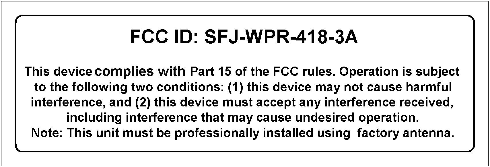
POWERWEB TECHNOLOGIES, INC. FCC ID: SFJ-WPR-418-3A EXTERNAL PHOTOS
Internal Photos
POWERWEB TECHNOLOGIES, INC. FCC ID: SFJ-WPR-418-3A INTERNAL PHOTOS
Test Report
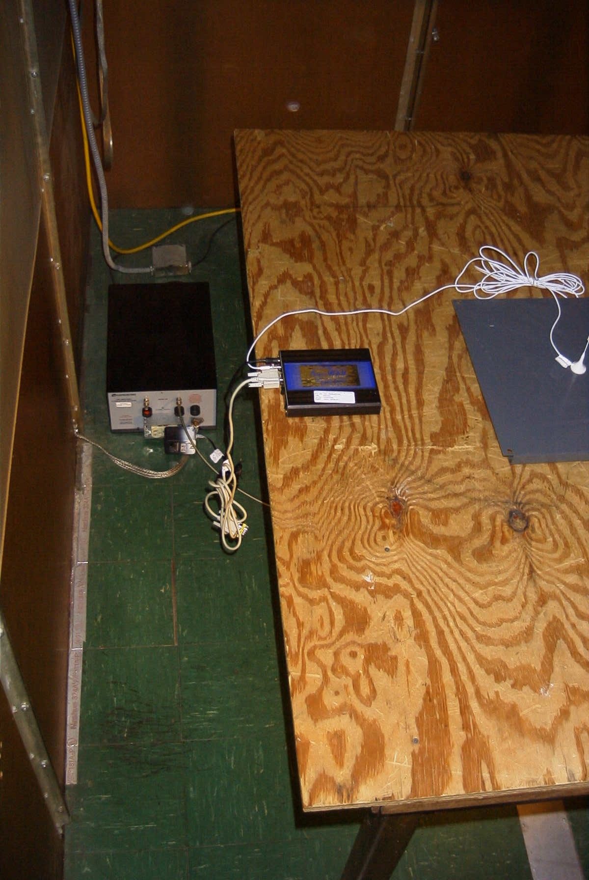
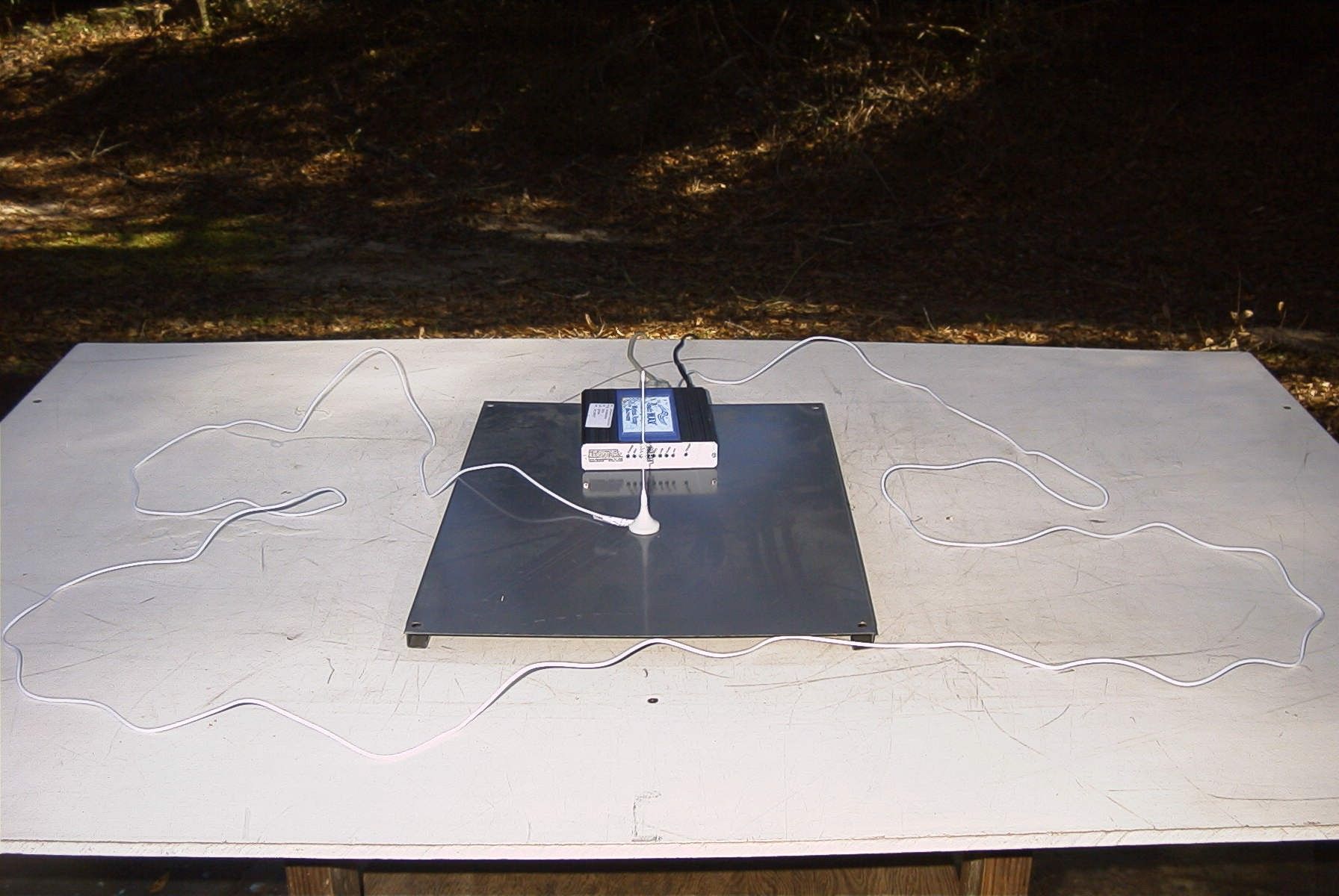
TIMCO ENGINEERING INC. 849 NW State Road 45 Newberry, Florida 32669 http://www.timcoengr.com 888.472.2424 F 352.472.2030 email: [email protected] APPLICANT: POWERWEB TECHNOLOGIES, INC. FCC ID: SFJ-WPR-418-3A REPORT #: P\POWERWEB_SFJ\242UT6\242UT6TestReport.doc COVER SHEET Test Report Product Name: WIRELESS ROUTER FCC ID: SFJ-WPR-418-3A Applicant: POWERWEB TECHNOLOGIES, INC. 415 EAST BALTIMORE PIKE MEDIA PA 19065 USA TIMCO ENGINEERING INC. 849 NW State Road 45 Newberry, Florida 32669 http://www.timcoengr.com 888.472.2424 F 352.472.2030 email: [email protected] APPLICANT: POWERWEB TECHNOLOGIES, INC. FCC ID: SFJ-WPR-418-3A REPORT #: P\POWERWEB_SFJ\242UT6\242UT6TestReport.doc TABLE OF CONTENTS TABLE OF CONTENTS APPLICANT: POWERWEB TECHNOLOGIES, INC. FCC ID: SFJ-WPR-418-3A TEST REPORT CONTAINING: PAGE 1.............TEST EQUIPMENT LIST PAGE 2.............TEST PROCEDURE PAGE 3-4...........RADIATED EMISSIONS TEST DATA PAGE 5-7...........POWERLINE CONDUCTED EMISSIONS PAGE 8.............DUTY CYCLE PAGE 9-11..........DUTY CYCLE PLOTS PAGE 12............OCCUPIED BANDWIDTH TEST DATA PAGE 13............OCCUPIED BANDWIDTH PLOT EXHIBIT INCLUDING: REQUEST FOR CONFIDENTIALITY LETTER BLOCK DIAGRAM SCHEMATIC INSTRUCTION MANUAL LABEL SAMPLE LABEL LOCATION EXTERNAL PHOTOGRAPHS INTERNAL PHOTOGRAPHS OPERATIONAL DESCRIPTION TEST SET UP PHOTOGRAPH TIMCO ENGINEERING INC. 849 NW State Road 45 Newberry, Florida 32669 http://www.timcoengr.com 888.472.2424 F 352.472.2030 email: [email protected] APPLICANT: POWERWEB TECHNOLOGIES, INC. FCC ID: SFJ-WPR-418-3A REPORT #: P\POWERWEB_SFJ\242UT6\242UT6TestReport.doc Page 1 of 13 EMC Equipment List Device Manufacturer Model Serial Number Cal/Char Date Due Date 3/10-Meter OATS TEI N/A N/A Listed 3/27/04 3/26/07 3-Meter OATS TEI N/A N/A Listed 1/11/06 1/10/09 Biconnical Antenna Eaton 94455-1 1057 CAL 12/12/05 12/12/07 Biconnical Antenna Eaton 94455-1 1096 CAL 8/17/04 8/17/06 Biconnical Antenna Electro- Metrics BIA-25 1171 CAL 4/29/05 4/29/07 Blue Tower Quasi-Peak Adapter HP 85650A 2811A01279 CAL 4/13/05 4/13/07 Blue Tower RF Preselector HP 85685A 2926A00983 CAL 9/5/05 9/5/07 Blue Tower Spectrum Analyzer HP 8568B 2928A04729 2848A18049 CAL 4/13/05 4/13/07 LISN Electro- Metrics ANS-25/2 2604 CAL 8/27/04 8/27/06 LISN Electro- Metrics EM-7820 2682 CAL 4/28/05 4/28/07 Log- Periodic Antenna Eaton 96005 1243 CAL 12/14/05 12/14/07 TIMCO ENGINEERING INC. 849 NW State Road 45 Newberry, Florida 32669 http://www.timcoengr.com 888.472.2424 F 352.472.2030 email: [email protected] APPLICANT: POWERWEB TECHNOLOGIES, INC. FCC ID: SFJ-WPR-418-3A REPORT #: P\POWERWEB_SFJ\242UT6\242UT6TestReport.doc Page 2 of 13 TEST PROCEDURE GENERAL: This report shall NOT be reproduced except in full without the written approval of TIMCO ENGINEERING, INC. RADIATION INTERFERENCE: The test procedure used was ANSI STANDARD C63.4-2003 using a HEWLETT PACKARD spectrum analyzer with a preselector. The bandwidth of the spectrum analyzer was 100 kHz with an appropriate sweep speed. The analyzer was calibrated in dB above a microvolt at the output of the antenna. The resolution bandwidth was 100 kHz and the video bandwidth was 300 kHz. The ambient temperature of the UUT was 98.3ºF with a humidity of 40%. FORMULA OF CONVERSION FACTORS: The Field Strength at 3m was established by adding the meter reading of the spectrum analyzer (which is set to read in units of dBuV) to the antenna correction factor supplied by the antenna manufacturer. The antenna correction factors are stated in terms of dB. The gain of the Preselector was accounted for in the Spectrum Analyzer Meter Reading. Example: Freq (MHz) METER READING + ACF = FS 33 20 dBuV + 10.36 dB = 30.36 dBuV/m @ 3m ANSI STANDARD C63.4-2003 10.1.7 MEASUREMENT PROCEDURES: The UUT was placed on a table 80 cm high and with dimensions of 1m by 1.5m. The UUT was placed in the center of the table. The table used for radiated measurements is capable of continuous rotation. The spectrum was scanned from 30 MHz to 10th harmonic of the fundamental. Peak readings were taken in three (3) orthogonal planes and the highest readings were converted to average readings based on the duration of "ON" time. When an emission was found, the table was rotated to produce the maximum signal strength. At this point, the antenna was raised and lowered from 1m to 4m. The antenna was placed in both the horizontal and vertical planes. Measurements were made by TIMCO ENGINEERING INC. at the registered open field test site located at 849 N.W. State Road 45, Newberry, Fl 32669. TIMCO ENGINEERING INC. 849 NW State Road 45 Newberry, Florida 32669 http://www.timcoengr.com 888.472.2424 F 352.472.2030 email: [email protected] APPLICANT: POWERWEB TECHNOLOGIES, INC. FCC ID: SFJ-WPR-418-3A REPORT #: P\POWERWEB_SFJ\242UT6\242UT6TestReport.doc Page 3 of 13 APPLICANT: POWERWEB TECHNOLOGIES, INC. FCC ID: SFJ-WPR-418-3A NAME OF TEST: RADIATION INTERFERENCE RULES PART NO.: 15.231 REQUIREMENTS: Fundamental Field Strength Field Strength of Frequency of Fundamental Harmonics and Spurious MHz dBuV Emissions (dBuV/m @ 3m) 40.66 to 40.70 67.04 47.04 70 to 130 61.94 41.94 130 to 174 61.94 to 71.48 41.94 to 51.48 174 to 260 71.48 51.48 260 to 470 71.48 to 81.94 51.48 to 61.94 470 and above 81.94 61.94 THE LIMIT FOR AVERAGE FIELD STRENGTH dBuV/m FOR THE FUNDAMENTAL FREQUENCY = 80.28 dBuV/m. NO FUNDAMENTAL IS ALLOWED IN THE RESTRICTED BANDS. THE LIMIT FOR AVERAGE FIELD STRENGTH dBuV/m FOR THE HARMONICS AND SPURIOUS FREQUENCIES = 60.28 dBuV/m. SPURIOUS IN THE RESTRICTED BANDS MUST BE LESS THAN 54 dBuV/m OR 15.209. TEST DATA: Emission Frequency MHz * Meter Reading dBuV Ant Pol Coax Loss dB Correction Factor dB Duty Cycle Factor dB Field Strength dBuV/m Margin dB 417.90 59.0 H 3.17 16.26 9.80 68.63 11.65 417.90 65.2 V 3.17 15.98 9.80 74.55 5.73 835.80 9.8 V 4.84 22.77 9.80 27.61 32.67 835.80 12.5 H 4.84 22.79 9.80 30.33 29.95 1,253.70 21.1 V 1.33 27.76 9.80 40.39 19.89 1,253.70 21.8 H 1.33 27.76 9.80 41.09 19.19 1,671.60 ** 24.2 H 1.54 …
Text truncated - open the document above for the full version.
Contact Information
Applicant
Lothar Budike(President)
Test Firm
Timco Engineering, Inc.Sid Sanders
Technical Specifications
| # | Rule Parts | Frequency Range | Power Output |
|---|---|---|---|
| 1 | 15.231 | 418 MHz - 418 MHz | - |
Other Applications from Powerweb Technologies, Inc.

SFJ-WPC-418-3A
Aug 19, 2004BALLAST CONTROL MODULE
Equipment Class
DSC - Part 15 Security/Remote Control Transmitter