SI5WUB500AUSB 2.0 802.11 a/b/g Wireless Network Adapter
U-MEDIA Communications, Inc.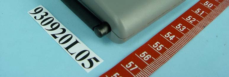
Click to zoom
Application Details
- Equipment Class
- DTS - Digital Transmission System
- Date of Grant
- Oct 28, 2004
- Application Purpose
- Original Equipment
- Date of Application
- Oct 28, 2004
- Equipment Note
- USB 2.0 802.11 a/b/g Wireless Network Adapter
- Frequency Range
- 5745.00000000 - 5825.00000000
- Company
- U-MEDIA Communications, Inc.
- Country
- Taiwan
Documents & Files
Document Text
Text extracted from the exhibit documents filed with the FCC. Open a document above to read the original.
Users Manual
WUB-500A FCC (1007x1269x16M jpeg)
Users Manual
Dual-band Wireless LAN USB Adapter User Manual Rev 0.8 2 Federal Communication Commission Interference Statement This equipment has been tested and found to comply with the limits for a Class B digital device, pursuant to Part 15 of the FCC Rules. These limits are designed to provide reasonable protection against harmful interference in a residential installation. This equipment generates, uses and can radiate radio frequency energy and, if not installed and used in accordance with the instructions, may cause harmful interference to radio communications. However, there is no guarantee that interference will not occur in a particular installation. If this equipment does cause harmful interference to radio or television reception, which can be determined by turning the equipment off and on, the user is encouraged to try to correct the interference by one of the following measures: - Reorient or relocate the receiving antenna. - Increase the separation between the equipment and receiver. - Connect the equipment into an outlet on a circuit different from that to which the receiver is connected. - Consult the dealer or an experienced radio/TV technician for help. This device complies with Part 15 of the FCC Rules. Operation is subject to the following two conditions: (1) This device may not cause harmful interference, and (2) this device must accept any interference received, including interference that may cause undesired operation. FCC Caution: Any changes or modifications not expressly approved by the party responsible for compliance could void the user's authority to operate this equipment. IMPORTANT NOTE: FCC Radiation Exposure Statement: This equipment complies with FCC radiation exposure limits set forth for an uncontrolled environment. This equipment should be installed and operated with minimum distance 20cm between the radiator & your body. If this device is going to be operated in 5.15 ~ 5.25GHz frequency range, then it is restricted in indoor environment only. This transmitter must not be co-located or operating in conjunction with any other antenna or transmitter. 3 CE Mark Warning This is a Class B product. In a domestic environment, this product may cause radio interference, in which case the user may be required to take adequate measures. This transmitter must not be co-located or operation in conjunction with any other antenna or transmitter. 4 Important Before using the Product, please carefully read the precautions described below to ensure proper operation. l Do not open the case or modify contents of the product. Seek the help of an authorized professional if some problem occurs with the product. l This product and other wireless devices may cause interference on each other and as result performance of the product may be affected. l Moving the PC during data transfer may damage the data being transferred. l Make sure to stop all wireless data transfer prior to removing the product from the PC in order to avoid damage to transferred data, PC or the product. l Please make sure the product will not cause hazards to other local equipment prior to operating in hospitals, airplanes, etc. or other locations susceptible to interference. l Do not expose the product to dangerous environment such as fire, chemicals or explosives, which may damage the product. l Unplug power and telephone cables from PCs and The product during severe thunderstorms or lightning. l Avoid dropping the product or subjecting it to excessive impacts l Avoid contact of the product with water since this may damage it. l Because exposing of the product to high humidity and/or extremely variable temperatures may deteriorate its performance, avoid as much as possible operating it under such environments l To prevent the risk of losing important data saved in the PC during installation of the product, it is advisable to backup all important files before installation. 5 Table of Contents 1. Network Implementation Using The product ..........................................................5 2. Before Installation ....................................................................................................6 3. Installing the Dual-band WLAN USB Adapter .........................................................7 4. The Client Utility Program ......................................................................................10 6 1. Network Implementation Using The product There are two possible types of wireless network configurations using the product: (1) Infrastructure (wireless network using an Access Point) Using the Client/Server or Master/Slave concept, an Access Point is used to link a wired network with wireless clients. Not only can the wireless clients access the wired network but they can also access each other via the Access Point. Multiple Access Points can be used in the same infrastructure network in order to extend the wireless network range or share the workload of handling more wireless clients. (2) Ad-Hoc (wireless network not using an Access Point) Since there is no Access Point to act as a link to a wired network, wireless network nodes can only access each other but cannot access a wired network or the Internet. 2. Before Installation Package Contents Unpack and confirm that the following contents (in addition to this User Manual) are included: Dual-band WLAN USB Adapter (1 ea.) Installation CD (1 ea.) Quick Installation Guide (1 ea.) To Prepare Before Installation Ask your system administrator for the following information, which you may need to input during installation: - Your SSID (group name of the wireless network) 7 - If you are using a fixed IP address: IP address, gateway address, and subnet mask info. To use the Dual-band Wireless LAN USB Adapter, the device must be equipped with an internal or external USB slot. You should have the latest drivers and utility software for the product (please visit our website for the latest drivers and utility software). 8 3. Installing the Du…
Text truncated - open the document above for the full version.
Cover Letter(s)
American Telecommunications Certification Body Inc. 6731 Whittier Ave, McLean, VA 22101 October 11, 2004 RE: U-MEDIA Communications, Inc. FCC ID: SI5-WUB500A or SI5WUB500A After a review of the submitted information, I have a few comments on the above referenced Application. 1) The 731 form shows a “-“ in the FCC ID, but the label does not. Please confirm the correct FCC ID for this device. 2) The spectrum analyzer given on page 33, 43, 46, 85, 96, 103, 110, 120, 126 & 129 appears out of calibration. 3) Compliance for the 5725 – 5825 Band appears to show some data for 15.247 and some data for 15.409. Note compliance must be completely shown to one band, the other, or both. Most data provided is for 15.247. However, the spectral density limit on page 131 should be +8 dBm. Please correct data as necessary. Timothy R. Johnson Examining Engineer mailto: [email protected] The items indicated above must be submitted before processing can continue on the above referenced application. Failure to provide the requested information may result in application termination. Correspondence should be considered part of the permanent submission and may be viewed from the Internet after a Grant of Equipment Authorization is issued. Please do not respond to this correspondence using the email reply button. In order for your response to be processed expeditiously, you must submit your documents through the AmericanTCB.com website. Also, please note that partial responses increase processing time and should not be submitted. Any questions about the content of this correspondence should be directed to the sender.
Cover Letter(s)
Dear Tim When we got the comments from you send, our client found the FCC ID need to change. So the FCC ID has been changed from SI5-WUB500A to SI5WUB500A. I have been revised the FCC ID for all documents and uploaded to website. And the comment has been solved. Please check. Thanks for your assistance! Best Regards Wendy Liao Page 1 of 1In 10/18/2004Printed for "Timothy R. Johnson" <[email protected]>
External Photos
Page 1 CONSTRUCTION PHOTOS OF EUT Page 2 Page 3
External Photos
Page 4 Page 5 Page 6 Page 7 Page 8
ID Label/Location Info
FCC ID Label Location
ID Label/Location Info
WUB-500A bottom label (836x419x16M jpeg)
Internal Photos
Page 4 Page 5 Page 6 Page 7 Page 8
Internal Photos
Page 9 Page 10 Page 11 Page 12
Operational Description
FCC ID: SI5WUB500A Report No.RF930920L05 Operational Description The transmitter of the EUT (USB2.0 802.11a/b/g wireless network adapter) is powered by host equipment via a USB interface. The antenna types used Dipole and Print antenna in this product, Dipole antenna with UFL connector and Printed antenna without antenna. Under normal use condition, the user has to keep at least 20cm separation distance between radiator and the body of the user. This device is a USB2.0 802.11a/b/g wireless network adapter, which operates in both of the 5GHz and 2.4GHz bands and can transmitting simultaneously, the maximum data rate could be 54Mbps. For more detailed instruction, please take a look at the user’s manual. FCC 15.407(c) states: The device shall automatically discontinue transmission in case of either absence of information to transmit or operational failure. These provisions are not intended to preclude the transmission of control or signaling information or the use of repetitive codes used by certain digital technologies to complete frame or burst intervals. Applicants shall include in their application for equipment authorization a description of hoe this requirement is met” Data transmission is always initiated by software, which is then pass down through the MAC, through the digital and analog baseband, and finally to the RF chip. Several special packets (ACKs, CTS, PSPoll, etc...) are initiated by the MAC. There are the only ways the digital baseband portion will turn on the RF transmitter, which it then turns off at the end of the packet. Therefore, the transmitter will be on only while one of the aforementioned packets are being transmitted.
Test Report
FCC ID: SI5WUB500A Report No.: RF930920L051Issued: Oct. 21, 2004 FCC TEST REPORT REPORT NO.: RF930920L05 MODEL NO.: WUB-500A RECEIVED: Sep. 14, 2004 TESTED: Sep. 14 ~ Oct. 20, 2004 APPLICANT: U-MEDIA Communications, Inc. ADDRESS: 9F, No.1, Jin-shan 7 th St., Hsinchu 300, Taiwan, R.O.C. ISSUED BY: Advance Data Technology Corporation LAB ADDRESS: 47 14th Lin, Chiapau Tsun, Linko Hsien, Taipei Hsien, Taiwan, R.O.C. LAB LOCATION: No. 19, Hwa Ya 2 nd Rd., Wen Hwa Tsuen, Kwei Shan Hsiang, Taoyuan Hsien 333, Taiwan, R.O.C. This test report consists of 169 pages in total. It may be duplicated completely for legal use with the approval of the applicant. It should not be reproduced except in full, without the written approval of our laboratory. The client should not use it to claim product endorsement by CNLA, A2LA or any government agencies. The test results in the report only apply to the tested sample. 0528 ILAC MRA No. 2177-01 FCC ID: SI5WUB500A Report No.: RF930920L052Issued: Oct. 21, 2004 Table of Contents 1.CERTIFICATION ......................................................................................................6 2.SUMMARY OF TEST RESULTS..............................................................................7 2.1 MEASUREMENT UNCERTAINTY ...........................................................................9 3.GENERAL INFORMATION ....................................................................................10 3.1GENERAL DESCRIPTION OF EUT ......................................................................10 3.2DESCRIPTION OF TEST MODES ........................................................................ 11 3.3GENERAL DESCRIPTION OF APPLIED STANDARDS........................................ 11 3.4DESCRIPTION OF SUPPORT UNITS...................................................................12 3.5CONFIGURATION OF SYSTEM UNDER TEST....................................................12 4.TEST TYPES AND RESULTS (FOR PART 802.11b & 802.11g)............................13 4.1CONDUCTED EMISSION MEASUREMENT.........................................................13 4.1.1LIMITS OF CONDUCTED EMISSION MEASUREMENT ......................................13 4.1.2TEST INSTRUMENTS ...........................................................................................13 4.1.3TEST PROCEDURES............................................................................................14 4.1.4DEVIATION FROM TEST STANDARD ..................................................................14 4.1.5TEST SETUP .........................................................................................................15 4.1.6EUT OPERATING CONDITIONS...........................................................................15 4.1.7TEST RESULTS.....................................................................................................16 4.2RADIATED EMISSION MEASUREMENT..............................................................28 4.2.1LIMITS OF RADIATED EMISSION MEASUREMENT ...........................................28 4.2.2TEST INSTRUMENTS ...........................................................................................29 4.2.3TEST PROCEDURES............................................................................................30 4.2.4DEVIATION FROM TEST STANDARD ..................................................................30 4.2.5TEST SETUP .........................................................................................................31 4.2.6EUT OPERATING CONDITIONS...........................................................................31 4.2.7TEST RESULTS.....................................................................................................32 4.2.8TEST RESULTS (A) ...............................................................................................34 4.2.9TEST RESULTS (B) ...............................................................................................40 4.36dB BANDWIDTH MEASUREMENT .....................................................................46 4.3.1LIMITS OF 6dB BANDWIDTH MEASUREMENT ..................................................46 4.3.2TEST INSTRUMENTS ...........................................................................................46 4.3.3TEST PROCEDURE ..............................................................................................47 4.3.4DEVIATION FROM TEST STANDARD ..................................................................47 4.3.5TEST SETUP .........................................................................................................47 4.3.6EUT OPERATING CONDITIONS...........................................................................47 4.3.7TEST RESULTS (A) ...............................................................................................48 4.3.8TEST RESULTS (B) ...............................................................................................52 4.4MAXIMUM PEAK OUTPUT POWER .....................................................................56 4.4.1LIMITS OF MAXIMUM PEAK OUTPUT POWER MEASUREMENT .....................56 4.4.2INSTRUMENTS .....................................................................................................56 4.4.1TEST PROCEDURES............................................................................................57 4.4.2DEVIATION FROM TEST STANDARD ..................................................................57 4.4.3TEST SETUP .........................................................................................................57 4.4.4EUT OPERATING CONDITIONS...........................................................................57 4.4.3TEST RESULTS (A) ...............................................................................................58 4.4.4TEST RESULTS (B) ...............................................................................................58 4…
Text truncated - open the document above for the full version.
Test Setup Photos
FCC ID: SI5WUB500A Report No.: RF930920L05165Issued: Oct. 21, 2004 6. PHOTOGRAPHS OF THE TEST CONFIGURATION CONDUCTED EMISSION TEST Test Mode 1 FCC ID: SI5WUB500A Report No.: RF930920L05166Issued: Oct. 21, 2004 Test Mode 2 FCC ID: SI5WUB500A Report No.: RF930920L05167Issued: Oct. 21, 2004 RADIATED EMISSION TEST Test Mode 1 FCC ID: SI5WUB500A Report No.: RF930920L05168Issued: Oct. 21, 2004 Test Mode 2
Contact Information
Applicant
Irving Liu(CEO)
Technical Contact
Advance Data Technology CorporationEllis Wu
[email protected]+886-3-318-3232
No. 19 Hwa Ya 2nd rd. · Kueishan Taoyuan · Taiwan
Non-Technical Contact
Advance Data Technology CorporationEllis Wu
[email protected]+886-3-318-3232
Test Firm
Bureau Veritas CPS (H.K.) Ltd. Taoyuan BranchTommy Wu
Technical Specifications
| # | Rule Parts | Frequency Range | Power Output |
|---|---|---|---|
| 2 | 15C | 5.75 GHz - 5.83 GHz | 26.00 mW |
Other Applications from U-MEDIA Communications, Inc.
SI5WST385L
Dec 29, 20092.4GHz Wireless 802.11n Adapter
Equipment Class
DTS - Digital Transmission System
SI5WUB710A
Apr 01, 20082.4GHz/5GHz Wireless USB Adapter
Equipment Class
DTS - Digital Transmission System
SI5WAP372L
Jan 15, 20082.4GHz 802.11n (draft 2.0) Wireless Access Point
Equipment Class
DTS - Digital Transmission System
SI5WPC370L
Aug 29, 20072.4GHz 802.11n (Draft 2.0) CardBus Card
Equipment Class
DTS - Digital Transmission System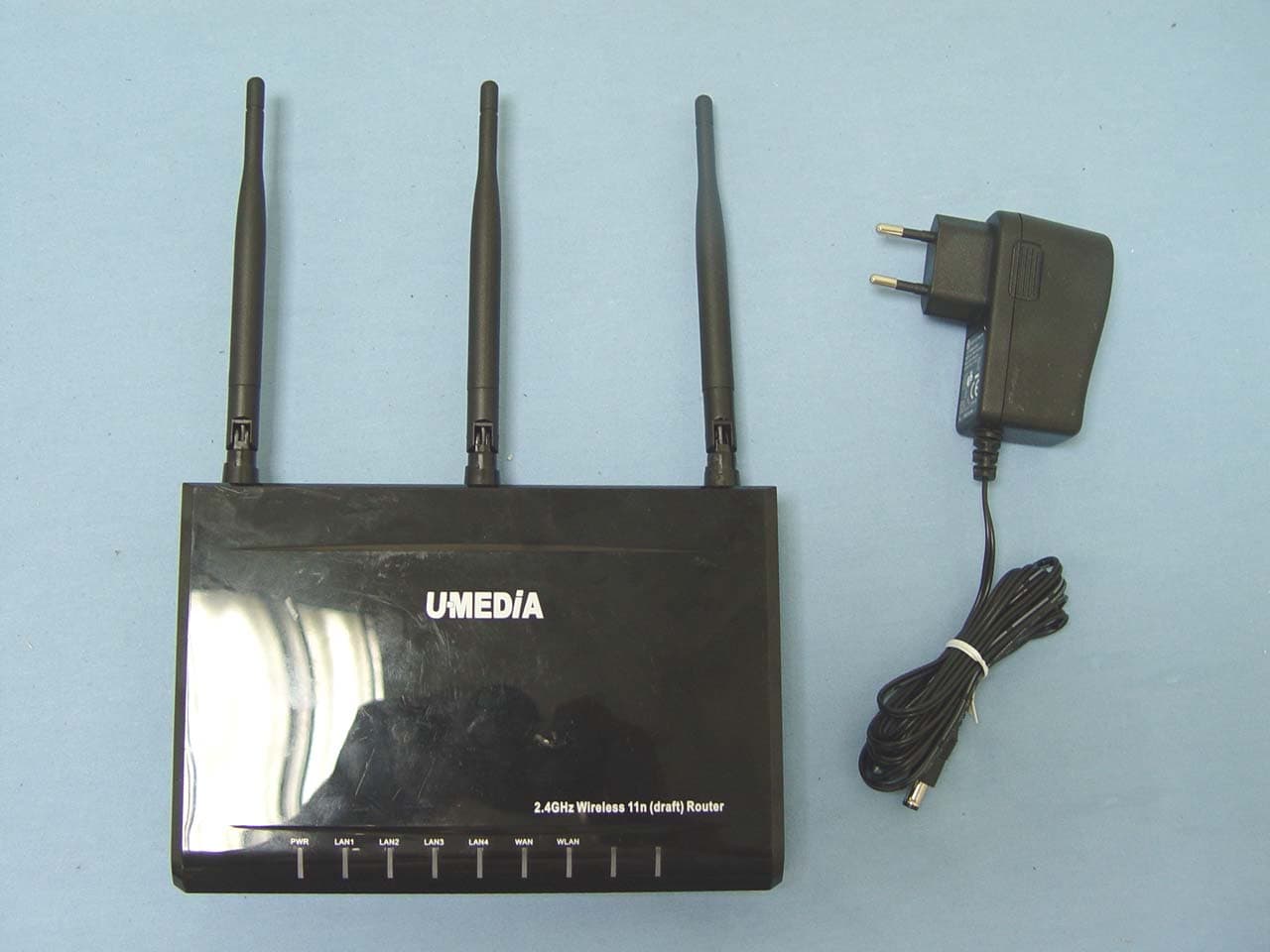
SI5WRT383U
Jul 29, 20072.4GHz 11n Draft 2.0 1+4 Port WLAN Router
Equipment Class
DTS - Digital Transmission System