SIV-WVM1101Adimos Wireless Video Module
Adimos, Inc
Click to zoom
Application Details
- Equipment Class
- NII - Unlicensed National Information Infrastructure TX
- Date of Grant
- Oct 06, 2004
- Application Purpose
- Original Equipment
- Date of Application
- Oct 06, 2004
- Equipment Note
- Adimos Wireless Video Module
- Frequency Range
- 5250.00000000 - 5350.00000000
- Company
- Adimos, Inc
- Country
- United States
Documents & Files
Document Text
Text extracted from the exhibit documents filed with the FCC. Open a document above to read the original.
Users Manual
ADIMOS Systems Ltd. ** Company Confidential ** WVM User Manual Page 1 of 1 Rev 1.00 Adimos Wireless Video Module User Manual Model: WVM-1101 The material contained herein is proprietary, privileged, and confidential. No disclosure thereof shall be made to third parties without the express written permission of ADIMOS Systems Ltd. ADIMOS Systems Ltd. reserves the right to alter the equipment specifications and descriptions in this publication without prior notice. No part of this publication shall be deemed to be part of any contract or warranty unless specifically incorporated by reference into such contract or warranty. ADIMOS Systems Ltd. ** Company Confidential ** WVM User Manual Page 2 of 2 Rev 1.00 Table of Contents 1. Introduction..................................................................................................................................3 1.1 Purpose and Scope...................................................................................................................3 1.2 Terms and Abbreviations..........................................................................................................3 2. References.....................................................................................................................................3 3. Configuration and Status Registers...............................................................................................3 3.1 General Description.................................................................................................................3 3.2 Register Details.......................................................................................................................3 3.2.1 Introduction.....................................................................................................................3 3.2.2 Register Summary............................................................................................................4 3.2.3 System Version................................................................................................................5 3.2.4 Video standard.................................................................................................................5 3.2.5 Video input port...............................................................................................................6 3.2.6 Video rate........................................................................................................................6 3.2.7 Country Code...................................................................................................................7 3.2.8 WLAN channel................................................................................................................7 3.2.9 Operation mode – local unit..............................................................................................8 3.2.10 Operation mode – remote unit...........................................................................................8 3.2.11 Timeout and Status of the Wireless I2C..............................................................................9 3.2.12 IR enable/disable..............................................................................................................9 3.2.13 Discrete Inputs Status.....................................................................................................10 3.2.14 Wireless ID....................................................................................................................10 3.2.15 RSSI Status....................................................................................................................10 3.2.16 PER Status.....................................................................................................................10 3.2.17 Do Installation Process....................................................................................................11 3.2.18 Discrete I/O Test Mode...................................................................................................11 3.2.19 Reset unit.......................................................................................................................11 ADIMOS Systems Ltd. ** Company Confidential ** WVM User Manual Page 3 of 3 Rev 1.00 1. Introduction 1.1 Purpose and Scope The Wireless Video Module product (WVM-1101) delivers video over wireless channel. It enables a wireless connection between a video source (DVD, VCR, PVR, STB, BS or PC) and a video display (standard TV, flat screen TV or video monitor). WVM-1101 operates in 5.15-5.35GHz. This document guides the user how to configure the WVM via a set of configuration and status registers. 1.2 Terms and Abbreviations BS Base Station CPU A microprocessor or microcontroller device DVD Digital Video Disk MPEG Motion Picture Expert Group N/A Not Applicable PVR Personal Video Recorder STB Set Top Box VCR Video Cassette Recorder WLAN Wireless Local Area Network WVM Wireless Video Module 2. References [1] Adimos WVM - Frequency Channel Tables 3. Configuration and Status Registers 3.1 General Description The WVM provides a set of internal registers, which can be modified or read via I2C interface. The values of these registers determine the behavior of the WVM. Each register has a unique sub-address. 3.2 Register Details 3.2.1 Introduction This section describes the internal registers. • Byte order: Byte0 is the first byte in a read/write operation. • Bit order: Bit 7 is the most significant bit within a byte. • 0x... is a hexadecimal number. ADIMOS Systems Ltd. ** Company Confidential ** WVM User Manual Page 4 of 4 Rev 1.00 3.2.2 Register Summary Sub-address Name Side Read/ Write Size [bytes] Function 0x00 System Version Tx, Rx R 4 System version ID 0x01 Set video standard Tx R/W 2 Set NTSC/PAL/SECAM/Auto. 0x02 Video standard status Tx, Rx R 1 Actual status of video standard 0x03 Select video input port Tx R/W 2 Select…
Text truncated - open the document above for the full version.
Cover Letter(s)
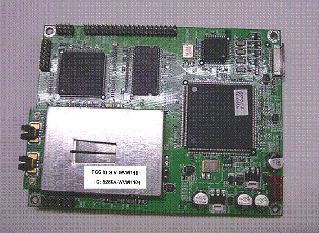
EXHIBIT 12: Modular Approval Requirements Limited Modular Approval is being requested for this device. There are eight requirements that the device must meet for full modular approval. The following paragraphs detail these requirements and the manner in which the device meets them. The module meets all of the technical specifications applicable to the frequency band of operation. The module has its own RF shielding. The module is equipped with Metal Shielding to cover RF Section. Refer to internal Photos). All modulation and data input(s) are buffered. All inputs to the modules are buffered through logic or microprocessor inputs. The module shall have its own power supply regulation and local reference oscillator. The module contains the rf reference oscillator within the module. Power supply regulation is not provided and is reliant on the power provided by the host system to be regulated. Limited modular approval is requested because of this. The modular transmitter must comply with the antenna requirements of Section 15.203 and 15.204(c). The certification submission contains a detailed description of the configuration of all antennas that will be used with the module. The module is equipped with unique (non-standard) antenna connector. Refer to internal photos). Installation instructions for the module explain that only these antennas may be used with the device and that the end user should not be able to access the antenna port or change antennas. For Industry Canada, the module meets certification labeling requirements. Host devices that contain separately certified modules do not need to be re-certified, provided that they meet the following conditions: • The host device, as a stand alone unit without any separately certified modules, complies with all applicable Radio Standards Specifications. • The host device and all the separately certified modules it contains jointly meet the safety requirements of RSS-102, if applicable. • The host device complies with the certification labeling requirements of each of the modules it contains. The module is appropriately labeled (refer to the label WVM-1101.pdf). For the FCC, the modular transmitter must be tested in a stand-alone configuration, i.e., the module must not be inside another device during testing. This is intended to demonstrate that the module is capable of complying with Part 15 emission limits regardless of the device into which it is eventually installed. Unless the transmitter module will be battery powered, it must comply with the AC line conducted requirements found in Section 15.207. Test data contained in this application is for the device tested as a stand- alone device. Radiated spurious emissions data and AC conducted emissions data demonstrating compliance with the requirements of Part 15 of the FCC rules for intentional radiators has been provided. For the FCC, the modular transmitter must be labeled with its own FCC ID number, and, if the FCC ID is not visible when the module is installed inside another device, then the outside of the device into which the module is installed must also display a label referring to the enclosed module. This exterior label can use wording such as the following: “Contains Transmitter Module FCC ID: SE6- WVM1101” or “Contains FCC ID: SE6-WVM1101.” The module is appropriately labeled (refer to the label and label location drawings contained within this application). Information to the integrator of this system regarding the labeling requirements for the host system are contained in the instructions provided with the module (refer to User Manual WVM-1101.doc). The modular transmitter must comply with any applicable RF exposure requirements. The module meets the requirements for a mobile device that may be used at separation distances of more than 20cm from the human body. Refer to the MPE calculation.
Cover Letter(s)
Response September 30, 2004 September 30, 2004 RE: Adimos, Inc FCC ID: SIV-WVM1101 Please see our responses to your questions. 1.) The supplied Internal Photographs are far too small and far too grainy to be of any practical value. Kindly submit revised photographs. The internal photographs of the rf transceiver module are clear. The photographs of the main circuit boards, onto which the rf transceiver is mounted, are the fuzzy pictures. These will be provided by the manufacturer and we will inform you once they have been uploaded. 2.) There are no External Photographs. The FCC requires separate Internal and External photograph exhibits – no exceptions. Please provide. The EUT is a module and has no enclosure, so there are no external photographs. We will provide the photographs of the module with the shield in place as external and those without as internal. 3.) There is no information presented for Label Location. Please provide. A revised label and label-location have been uploaded. 4.) Is this to be considered a “Modular Approval”? If so, the requirements of DA 00-1407 must be followed. Yes, please refer to file uploaded “Modular Exhibit.pdf”. Note that the device does not contain voltage regulation for all of the different voltages used by the rf transceiver, and so a limited modular approval is requested that limits use of the module to Adimos and authorized OEMS. 5.) I am also concerned with the functionality of this device. The Commission usually requires devices that contain differing functions to be submitted as separate devices despite sharing the same RF portion. It is my suggestion that the “Tx” and “Rx” versions be segregated. If not, please provide justification for Certification under one single FCC ID. The transmitter for this device is identical in all its functions. The difference between the AV transmitter and AV receiver is the type of connections. That part of the device that differs is separate from the transmitter subject to UNII rules. Response September 30, 2004 6.) No compliance information is included in the Manual. Please supply all relevant and required information. Please refer to revised manual 7.) If Modular Approval is sought, please provide instructions for OEM integrators. Please refer to revised manual 8.) The Manual appears to indicate that “country codes” can be set via software. This is not permitted under FCC and Canadian rules. Removed, Please refer to revised manual 9.) It is impossible to identify the different components used in the Test Setup photographs. Please provide better Test Setup Photographs. We are providing the original jpg format photographs, which are much clearer. 10.) Does this device use “F” style antennas? If so, then radiated testing with the antennas lying directly on the table is not permitted. You will need to retest with a minimum 1” non-conductive spacer under the antennas. The antennas are not “F” style. They connected using UDFL connectors to the radio module on the AV transmitter and AV receiver. 11.) Please provide details on the antennas including photos for this device. Please refer to the new test setup photos. If you need additional close-up photos we can provide these. We are also sending information for the antenna. 12.) You are requesting 62mW across the entire 5150-5359MHz band on your Application forms. This is not permitted. The limit from 5150-5250 is 50mW. There are multiple references within this filing across many Exhibits that may require modification. The device is 46 mW in the 5150 to 5250 band and 62 mW in the 5250 to 5350 band. We are providing a revised application form. 13.) Kindly refer to your Block Diagram. The “Toshiba” RF module does not contain any information. Please provide a block diagram for the module. We are providing a block diagram for the RF module. 14.) The Block Diagram for WVM-TX shows provisions for an External Antenna. Under what conditions will an external antenna be utilized? The external antenna refers to the fact that the antennas for this module are connected using a UDFL connector. The integrator of the module is instructed to ensure that the connector is not accessible to the end user. 15.) Please explain how compliance with 15.407(c) will be maintained. Please refer to addendum to the Technical Description Response September 30, 2004 16.) Please show how compliance with 15.407(e) will be maintained. This information does not appear in the Manual. Please refer to addendum to the Technical Description. 17.) Please provide an attestation to the requirements of 15.407(f). Please refer to revised manual that requires a separation distance of 20cm to ensure compliance with FCC RF radiation exposure requirements. 18.) Antenna integration requirements as specified in your Test Report [page 8] appear to be missing. Please refer to revised manual requiring the integrator of the module to ensure that the antenna connector is not accessible to the end user. 19.) There is conflicting information with regards to RF power measurement. Was a power meter or spectrum analyzer used? If a power meter, please provide details on the video bandwidth of this device. If a spectrum analyzer, please provide details on the integration algorithm. A spectrum analyzer was used for all power measurements. See page 6 of 32 of Exhibit 2 for details. The following documents supporting this response have been uploaded to the ATCB website: • User Manual 10-01-04.doc • External Photographs.doc • RF Module Block Diagram-10-01-04.doc • Antenna info.pdf • Label Location.JPG • Tech Description addendum 10-01-04.doc • ATCB Form 731 Revised.doc • Modular exhibit rev 2.doc Please advise of the detailed photographs of the non-rf circuitry are required and they will be uploaded as soon as they have been provided by Adimos. Regards, David W. Bare
Cover Letter(s)
American Telecommunications Certification Body Inc. 6731 Whittier Ave, McLean, VA 22101 September 29, 2004 RE: Adimos, Inc FCC ID: SIV-WVM1101 I have a few comments on this Application. Depending on your responses, kindly understand there may be additional comments. 1.) The supplied Internal Photographs are far too small and far too grainy to be of any practical value. Kindly submit revised photographs. 2.) There are no External Photographs. The FCC requires separate Internal and External photograph exhibits – no exceptions. Please provide. 3.) There is no information presented for Label Location. Please provide. 4.) Is this to be considered a “Modular Approval”? If so, the requirements of DA 00-1407 must be followed. 5.) I am also concerned with the functionality of this device. The Commission usually requires devices that contain differing functions to be submitted as separate devices despite sharing the same RF portion. It is my suggestion that the “Tx” and “Rx” versions be segregated. If not, please provide justification for Certification under one single FCC ID. 6.) No compliance information is included in the Manual. Please supply all relevant and required information. 7.) If Modular Approval is sought, please provide instructions for OEM integrators. 8.) The Manual appears to indicate that “country codes” can be set via software. This is not permitted under FCC and Canadian rules. 9.) It is impossible to identify the different components used in the Test Setup photographs. Please provide better Test Setup Photographs. 10.) Does this device use “F” style antennas? If so, then radiated testing with the antennas lying directly on the table is not permitted. You will need to retest with a minimum 1” non-conductive spacer under the antennas. 11.) Please provide details on the antennas including photos for this device. 12.) You are requesting 62mW across the entire 5150-5359MHz band on your Application forms. This is not permitted. The limit from 5150-5250 is 50mW. There are multiple references within this filing across many Exhibits that may require modification. 13.) Kindly refer to your Block Diagram. The “Toshiba” RF module does not contain any information. Please provide a block diagram for the module. 14.) The Block Diagram for WVM-TX shows provisions for an External Antenna. Under what conditions will an external antenna be utilized? 15.) Please explain how compliance with 15.407(c) will be maintained. 16.) Please show how compliance with 15.407(e) will be maintained. This information does not appear in the Manual. 17.) Please provide an attestation to the requirements of 15.407(f). 18.) Antenna integration requirements as specified in your Test Report [page 8] appear to be missing. 19.) There is conflicting information with regards to RF power measurement. Was a power meter or spectrum analyzer used? If a power meter, please provide details on the z Page 2 September 29, 2004 video bandwidth of this device. If a spectrum analyzer, please provide details on the integration algorithm. Regards, William H. Graff President and Director of Engineering mailto: [email protected] The items indicated above must be submitted before processing can continue on the above referenced application. Failure to provide the requested information may result in application termination. Correspondence should be considered part of the permanent submission and may be viewed from the Internet after a Grant of Equipment Authorization is issued. Please do not respond to this correspondence using the email reply button. In order for your response to be processed expeditiously, you must submit your documents through the AmericanTCB.com website. Also, please note that partial responses increase processing time and should not be submitted. Any questions about the content of this correspondence should be directed to the sender.
External Photos
External Photographs – AV Transmitter on left, AV Receiver on the right – top view External Photographs – AV Transmitter on right, AV Receiver on the left – bottom view
ID Label/Location Info
FCC ID:SIV-WVM1101 Test to Comply With FCC Standards Model WVM-1101 C anada IC : 5280A-WVM1101 Adimos
RF Exposure Info
MPE Calculations The device is not a portable device (i.e. intended to be worn on the body or be hand- held), so it is classified as being either a mobile device or a fixed mounted device. The user’s manual specifies a minimum separation distance of at least 20cm, consistent with this classification. FCC part 1.1310, Table 1 limits the power density for uncontrolled exposure. The power density, S (mW/cm 2 ), calculated from the maximum EIRP, P t (mW) and the distance, d (m), between the transmitting antenna and the closest person, can be calculated using: S = P t /(4 pd 2 ) Frequency MPE Limit (mW/cm 2 ) Output Power (mW) Max. Antenna Gain (dBi) EIRP (mW) Pd at 20cm (mW/cm 2 ) Distance where Pd = limit (cm) 5150 to 5350 MHz 1.00 61.7 5.6 223.9 0.04 4.2 As shown in the calculations above, the power density 20cm from the device is below the maximum permitted level for uncontrolled exposure.
Test Report
File: R56760 Page 1 of 18 Electromagnetic Emissions Test Report and Application for Grant of Equipment Authorization pursuant to FCC Part 15, Subpart E (UNII Devices) and Industry Canada RSS 210 Issue 5 (LELEAN Devices) on the Adimos, Inc. Model: WVM-1101 FCC ID: SIV-WVM1101 UPN: 5280A-W VM1101 GRANTEE: Adimos, Inc. 101 1st Street Los Altos, CA 94022 TEST SITE: Elliott Laboratories, Inc. 684 W. Maude Avenue Sunnyvale, CA 94086 REPORT DATE: September 23, 2004 FINAL TEST DATES: July 15, July 17 and July 31, 2004 AUTHORIZED SIGNATORY: ______________________________ David W. Bare Chief Technical Officer Elliott Laboratories, Inc. is accredited by the A2LA, certificate number 2016-01, to perform the test(s) listed in this report. This report shall not be reproduced, except in its entirety, without the written approval of Elliott Laboratories, Inc. Elliott Laboratories, Inc. -- EMC Department Test Report Report Date: September 23, 2004 File: R56760 Page 2 of 18 Pages DECLARATIONS OF COMPLIANCE Equipment Name and Model: WVM-1101 Manufacturer: Adimos, Inc. 101 1st Street Los Altos, CA 94022 Tested to applicable standards: RSS-210, Issue 5, November 2001 (Low Power Licence-Exempt Radiocommunication Devices) FCC Part 15 Subpart E (UNII Devices) Measurement Facility Description Filed With Industry Canada: File Number: IC 2845-2 I declare that the testing was performed or supervised by me; that the test measurements were made in accordance with the above mentioned departmental standards (through the use of ANSI C63.4 as detailed in section 5.3 of RSS-210, Issue 5); and that the equipment performed in accordance with the data submitted in this report. Signature ______________________________ Name David W. Bare Title Chief Technical Officer Company Elliott Laboratories Inc. Address 684 W. Maude Ave Sunnyvale, CA 94086 USA Date: September 23, 2004 Maintenance of compliance with the above standards is the responsibility of the manufacturer. Any modification of the product that may result in increased emissions should be checked to ensure compliance has been maintained (i.e., printed circuit board layout changes, different line filter, different power supply, harnessing or I/O cable changes, etc.). Elliott Laboratories, Inc. -- EMC Department Test Report Report Date: September 23, 2004 File: R56760 Page 3 of 18 Pages TABLE OF CONTENTS COVER PAGE...................................................................................................................................................................................1 DECLARATIONS OF COMPLIANCE......................................................................................................................................2 TABLE OF CONTENTS..............................................................................................................................................................3 SCOPE............................................................................................................................................................................................4 OBJECTIVE...................................................................................................................................................................................4 SUMMARY OF RESULTS...........................................................................................................................................................5 MEASUREMENT UNCERTAINTIES....................................................................................................................................6 EQUIPMENT UNDER TEST (EUT) DETAILS..........................................................................................................................7 GENERAL...................................................................................................................................................................................7 OTHER EUT DETAILS.............................................................................................................................................................7 ENCLOSURE..............................................................................................................................................................................7 MODIFICATIONS.....................................................................................................................................................................7 SUPPORT EQUIPMENT...........................................................................................................................................................8 EUT INTERFACE PORTS........................................................................................................................................................8 EUT OPERATION DURING TESTING...................................................................................................................................8 ANTENNA REQUIREMENTS.................................................................................................................................................8 TEST SITE......................................................................................................................................................................................9 GENERAL INFORMATION.....................................................................................................................................................9 CONDUCTED EMISSIONS CONSIDERATIONS.................................................................................................................9 RADIATED EMISSIONS CONSIDERATIONS....................................................................................................................9 MEASUREMENT INSTRUMENTATION................................................................................................................................10 RECEIVER…
Text truncated - open the document above for the full version.
Contact Information
Applicant
Malcolm Caraballo(VP, Operations)
Technical Contact
Elliott Laboratories, Inc.David W Bare
[email protected]408 245 7800
684West Maude Ave · Sunnyvale, California · United States
Test Firm
Element Materials Technology Fremont NewarkDavid Bare
Technical Specifications
| # | Rule Parts | Frequency Range | Power Output | Tolerance |
|---|---|---|---|---|
| 2 | 15E | 5.25 GHz - 5.35 GHz | 62.00 mW | 100 ppm |