SJ7HYPRO43HyPro Radio Remote Control
NBB Controls & Components GmbH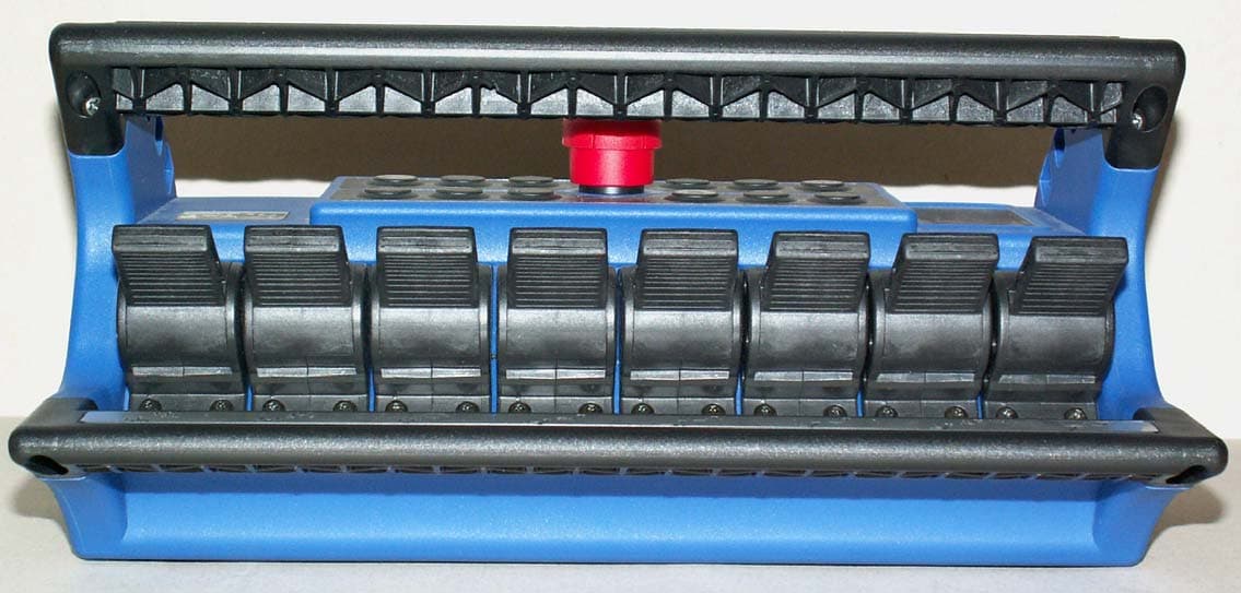
Click to zoom
Application Details
- Equipment Class
- DSC - Part 15 Security/Remote Control Transmitter
- Date of Grant
- Jul 17, 2007
- Application Purpose
- Original Equipment
- Date of Application
- Jul 17, 2007
- Equipment Note
- HyPro Radio Remote Control
- Frequency Range
- 433.10000000 - 434.75000000
- Country
- Germany
Documents & Files
Document Text
Text extracted from the exhibit documents filed with the FCC. Open a document above to read the original.
Users Manual
® Compact-M, Compact-VCompact-M,Compact-V HyPro-8USAHyPro-8USA R-16, R-CANR-16,R-CAN HyPro-6USAHyPro-6USA Receiver Type Factory No. / Version Frequency Transmitter Type / Version Factory No. Frequency OPERATING INSTRUCTIONSOPERATINGINSTRUCTIONS % % % Portable transmitter. Receiver with integrated mounting holes. Multi-pin connecting cable for the receiver according to your specifications. For explanatory notes on obtaining an operating permit please refer to registration docu- ments enclosed in the appendix of this operating instruction. Observe all applicable work- safety and accident prevention regulations carefully. Only fully trained, authorized per- sonnel may use the NBB radio control equipment. Components, etc. built into the NBB equipment for safety purposes must be regularly inspected. Failure to observe these recommendations will put both you yourself and others at risk. Under these circumstances, NBB rescinds the guarantee and any other form of liability. This radio control unit is designed exclusively for the control of construction machines and industrial plants. Only under these conditions are the safety systems (STOP, resp. EMERGENCY STOP, zero setting) fully effective. No other form of use is permitted. Any non-observance of this condition will relieve NBB of all liability. Optional: The actual delivery specification is as detailed on the confirmation of order or the delivery note accompanying the goods! Even if you are accustomed to working with radio control systems, read these operating instructions carefully before using this equipment. Only this document contains the latest information relating to your NBB radio control system. If the NBB radio control unit develops a fault, it must be shut down immediately. The trans- mitter should be switched off with the STOP key, resp. EMERGENCY STOP switch. The connecting cable must be disconnected at the receiver from the connecting socket (ter- minal) of the unit to be controlled . The repair of the equipment must not be carried out ot- her than by NBB or an NBB authorized technician. 1. STANDARD SPECIFICATION 2. SAFETY PRECAUTIONS 3. TRANSMITTER Switching on:To make the unit ready for use, unscrew the screw plug of the battery com- partment on the back of the transmitter and remove the cover. Insert 2 charged AA Mignon batteries 1,2V NiMH (or batteries 1,5V - not rechargeable) into the battery Compartment, close the cover and tighten the screw plug again. Rechargeable batteries (NiMH or NiCd) must be fully charged before first use! Never attempt to charge standard non rechargeable 1,5V AA batteries! Page 1 .. 3. TRANSMITTERHyPro STOP START AKKU LEER DISPLAY FUNK ON DISPLAY AKKU The power supply to the transmitter is activated with the “STOP” key, resp. EMERGENCY STOP switch. (When pressed, the EMERGENCY STOP switch can also be secured by removing the key cap.) The green LED on the transmitter control panel must flash regularly. Commands can now be put in by means of the controls. When the red "Battery" indicator lamp lights up, the batteries (rechargeable or not rechargeable) are nearly empty. The transmitter can be operated for approximately 30 minutes more in this condition. During this time, bring the unit to a safe position, switch off the transmitter and install 2 charged AA Mignon batteries 1,2V NiMH (or batteries 1,5V - not rechargeable). The transmitter switches off automatically, if the keys are not pres- sed within a specified time. The LED goes out. Optional: Transmitter for continuous operation possible. Energy saving function: *The duration of this stand-by can be specified when ordering. Operation: The red dot flashes. Quickly flashing: Bat- teries are nearly empty. T ransmitter can be operated for appr. 30 minutes more. Page 2 4. RECEIVER R-16, R-CAN Compact-M, Compact-V Compact-MR-16R-CANCompact-V . Mounting possibility of the receiver R-16, R-CAN or the Compact-M. Mounting possibility of the receiver Compact-V. The receiver is connected to the unit to be controlled with the multi-pin connecting cable supplied. Please observe the instructions issued by the manufacturer of the unit to be controlled! The power supply of the receiver is generally effected by the connecting cable. We recommend urgently to realize this connection via a central, well accessible, multi-pin plug connector (for example HTS-plug connector series HE/HB/HN/HA or comparable ones of other manufacturers) to make possible a quick and clear fault diagnosis in the service case and to take off the receiver without an expenditure of assembly. In general, an earth lead is required in case the units to be controlled have not pre- viously been operated by radio control. Failing this, the receiver electronic circuit will not receive any power supply. Ensure that the opera- ting voltage of the receivercomplies with the electrical specifications of the unit to be controlled. The applicable operating voltage is specified in the supp- lement. Never expose the receiver to a high pressure cleaning jet. This applies to the transmitter also. The receiver should always be fixed vertically at the outside panel of the swit- ching cabinet. (The antenna should always reach over the top of the panel.) You have to make sure that the antenna is not shielded by metal parts totally or part- ly. Mounting the receiver in a cabine or in a switching cabinet the antenna should be layed with an extension cable to the outside and be attached with the fastening strapping as horizontally as possible with distance to the shielding metal parts. In general the antenna should always be mounted in such a way so that the antenna is still visible with each change of position of the transmitter. % % % % % % WRONG Mounting on a tower slewing crane. RIGHT WRONG RIGHT Top slewing crane: Mount the antenna with extension cable horizontally. Page 3 5. OPERATING THE UNIT + 1 2 3 4 ON/HORN RADIO ON/ EMERGENCY STOP FREQUENCY CHANGE FREQUENCY CHANGE Safety equipment in the NBB-radio remote cont…
Text truncated - open the document above for the full version.
Cover Letter(s)
NBB CONTROLS + COMPONENTS AKTIENGESELLSCHAFT · SITZ: 75248 ÖLBRONN - DÜRRN · OTTO - HAHN - STR. 3-5 · REGISTERGERICHT MANNHEIM HRB 505160 VORSTAND: DIPL.- ING. THOMAS BURCHARD, WOLFGANG BREDOW · VORSITZENDER DES AUFSICHTSRATES: BERND MAISENBACHER ® TELEFON 0 72 37 / 9 99 - 261 TELEFAX 0 72 37 / 9 99 - 196 NBB CONTROLS + COMPONENTS AG OTTO-HAHN-STR. 3-5 · D-75246 ÖLBRONN - DÜRRN 14/05/2007 Thomas Burchard President NBB Controls + Components AG, DE-75248 Oelbronn-Duerrn, Germany To Whom It May Concern: Please be advised that NBB Controls + Components AG authorizes Washington Laboratories, Ltd. to act on our behalf, until otherwise notified, for applications submitted to American Telecommunications Certification Body, Inc. (ATCB). We certify that we are not subject to denial of federal benefits, that includes FCC benefits, pursuant to Section 5301 of the Anti-Drug Abuse ACT of 1988, U.S.C. 862. Further, no party, as defined in 47 CFR 1.2002(b), to the application is subject to denial of federal benefits, that includes FCC benefits. Thank you for your attention to this matter. American Telecommunications Certification Body, Inc. 6731 Whittier Avenue Suite C110 McLean, VA 22101
Cover Letter(s)
24.05.2007 Re: Certification Application FCC ID: SJ7HYPRO43 Please be advised that under the provision of 47 CFR 0.459 the following exhibits are to be held confidential on behalf of NBB Controls + Components AG: * Schematics Block Diagram Operational Description Parts Lists The application contains technical information that NBB Controls + Components AG deems to be trade secrets and proprietary. If made public, the information might be used to the disadvantage of the applicant in the market place. Thank you for your attention to this matter. T Thomas Burchard * NBB CONTROLS + COMPONENTS AKTIENGESELLSCHAFT · SITZ: 75248 ÖLBRONN - DÜRRN · OTTO - HAHN - STR. 1-3 · REGISTERGERICHT MANNHEIM HRB 505160 VORSTAND: DIPL.- ING. THOMAS BURCHARD, WOLFGANG BREDOW · VORSITZENDER DES AUFSICHTSRATES: BERND MAISENBACHER ® American Telecommunications Certification Body, Inc. 6731 Whittier Avenue Suite C110 McLean, VA 22101 TELEFON 0 72 37 / 9 99 - 261 TELEFAX 0 72 37 / 9 99 - 196 NBB CONTROLS + COMPONENTS AG OTTO-HAHN-STR. 3-5 · D-75246 ÖLBRONN - DÜRRN
External Photos
External Photos ©2007 Washington Laboratories, Ltd FCC ID: SJ7HYPRO43 External Photos ©2007 Washington Laboratories, Ltd FCC ID: SJ7HYPRO43 External Photos ©2007 Washington Laboratories, Ltd FCC ID: SJ7HYPRO43
ID Label/Location Info
Label Location ©2007 Washington Laboratories, Ltd FCC ID: SJ7HYPRO43 HyPRO Serial-No.: 9994770192 FCC ID: SJ7HYPRO43 IC: 2634B-HYPRO43 This device complies with Part 15 of the FCC Rules. Operation is subject to the following two conditions; (1) this device may not cause harmful interference, and (2) this device must accept any interference received, including interference that may cause undesired operation. NBB Controls + Components AG Freq: 433.1 – 434.75MHz 0507
Internal Photos
Internal Photos ©2007 Washington Laboratories, Ltd FCC ID: SJ7HYPRO43 Internal Photos ©2007 Washington Laboratories, Ltd FCC ID: SJ7HYPRO43 Joystick PCB Top Joystick PCB Bottom Main PCB Top Internal Photos ©2007 Washington Laboratories, Ltd FCC ID: SJ7HYPRO43 Main PCB Top Shield Removed Main PCB Bottom
Test Report
Document 9722-01, Rev. 0 FCC ID: SJ7HYPRO43 IC ID: 2634B-HYPRO43 FCC and IC Certification Test Report Washington Laboratories, Ltd June 2007 FCC & Industry Canada Certification Test Report for NBB Controls & Components AG FCC ID: SJ7HYPRO43 IC ID: 2634B-HYPRO43 June 29, 2007 Prepared for: NBB Controls & Components AG Otto-Hahn-Straße 1-3 D-75248 Ölbronn-Dürrn Prepared By: Washington Laboratories, Ltd. 7560 Lindbergh Drive Gaithersburg, Maryland 20879 FCC & IC Certification Test Report Document 9722-01, Rev. 0 FCC ID: SJ7HYPRO43 IC ID: 2634B-HYPRO43 FCC and IC Certification Test Report Washington Laboratories, Ltd June 2007 Page 1 of 17 FCC & Industry Canada Certification Test Report for the NBB Controls & Components AG HyPro Radio Remote Control FCC ID: SJ7HYPRO43 IC ID: 2634B-HYPRO43 June 29, 2007 WLL JOB# 9722 Prepared by: James Ritter Compliance Engineer Reviewed by: Steven D. Koster EMC Operations Manager Document 9722-01, Rev. 0 FCC ID: SJ7HYPRO43 IC ID: 2634B-HYPRO43 FCC and IC Certification Test Report Washington Laboratories, Ltd June 2007 Page 2 of 17 Abstract This report has been prepared on behalf of NBB Controls & Components AG to support the attached Application for Equipment Authorization. The test report and application are submitted for a Periodic Intentional Radiator under Part 15.231 of the FCC Rules and Regulations and Spectrum Management and Telecommunications Policy RSS-210 of Industry Canada. This Federal Communication Commission (FCC) Certification Test Report documents the test configuration and test results for a NBB Controls & Components AG HyPro Radio Remote Control. Testing was performed on an Open Area Test Site (OATS) of Washington Laboratories, Ltd, 7560 Lindbergh Drive, Gaithersburg, MD 20879. Site description and site attenuation data have been placed on file with the FCC's Sampling and Measurements Branch at the FCC laboratory in Columbia, MD. The Industry Canada OATS numbers are 3035A-1 and 3035A-2 for Washington Laboratories, Ltd. Site 1 and Site 2, respectively. Washington Laboratories, Ltd. has been accepted by the FCC and approved by NIST NVLAP (NVLAP Lab Code: 200066-0) as an independent FCC test laboratory. The NBB Controls & Components AG HyPro Radio Remote Control complies with the limits for a Periodic Intentional Radiator device under FCC Part 15.231 and Industry Canada RSS-210. Document 9722-01, Rev. 0 FCC ID: SJ7HYPRO43 IC ID: 2634B-HYPRO43 FCC and IC Certification Test Report Washington Laboratories, Ltd June 2007 Page 3 of 17 Table of Contents Abstract ............................................................................................................................... ii 1 Introduction..............................................................................................................4 1.1 Compliance Statement .........................................................................................4 1.2 Test Scope ............................................................................................................4 1.3 Contract Information............................................................................................4 1.4 Test Dates ............................................................................................................4 1.5 Test and Support Personnel .................................................................................4 2 Equipment Under Test .............................................................................................5 2.1 EUT Identification & Description .......................................................................5 2.2 Test Configuration ...............................................................................................5 2.3 Testing Algorithm................................................................................................5 2.4 Test Location .......................................................................................................5 2.5 Measurements ......................................................................................................6 2.5.1 References........................................................................................................6 2.6 Measurement Uncertainty....................................................................................6 3 Test Equipment ........................................................................................................7 4 Test Results ..............................................................................................................8 4.1 Transmission Cessation from Time-of-Release...................................................8 4.2 Occupied Bandwidth: (FCC Part §2.1049) ..........................................................9 4.3 Radiated Spurious Emissions.............................................................................11 4.3.1 Test Procedure ...............................................................................................12 List of Tables Table 1. Device Summary................................................................................................... 5 Table 2: Test Equipment List............................................................................................. 7 Table 3. Occupied Bandwidth Results.............................................................................. 11 Table 4. Radiated Emissions Test Data –Low Channel @ 433.1MHz............................ 13 Table 5. Radiated Emissions Test Data –Center Channel @ 433.9MHz ........................ 14 Table 6. Radiated Emissions Test Data, -High Channel @ 434.75MHz......................... 16 List of Figures Figure 1. Time Period: Release to Termination of Transmission....................................... 8 Figure 2. Occupied Bandwidth, Low Channel ................................................................... 9 Figure 3. Occupied Bandwidth, Mid Channel .....................................…
Text truncated - open the document above for the full version.
Test Setup Photos
Test Setup Photos ©2007 Washington Laboratories, Ltd Test Setup Photos ©2007 Washington Laboratories, Ltd Test Setup Photos ©2007 Washington Laboratories, Ltd Test Setup Photos ©2007 Washington Laboratories, Ltd Test Setup Photos ©2007 Washington Laboratories, Ltd
Contact Information
Applicant
Thomas Burchard(President)
Technical Contact
Washington Laboratories, LtdSteven Koster
[email protected]301 216 1500
7560 Lindbergh Drive · Gaithersburg, Maryland · United States
Non-Technical Contact
Washington Laboratories, LtdBrian Dettling
[email protected]301 216 1500
Test Firm
Washington Laboratories, Ltd.John Repella
Technical Specifications
| # | Rule Parts | Frequency Range | Power Output |
|---|---|---|---|
| 1 | 15.231 | 433.1 MHz - 434.75 MHz | - |