FCCID.CO- FCC ID Database
HomeCompaniesEquipment ClassesSearch

Β© 2026 FCC ID Database. All rights reserved.

AboutContactData sourced from FCC public records
  1. Home/
  2. CM Precision Technology LTD./
  3. SJDGSMMOD51

SJDGSMMOD51FM MODULATOR

CM Precision Technology LTD.

Application Details

Equipment Class
DXX - Part 15 Low Power Communication Device Transmitter
Date of Grant
Nov 17, 2004
Application Purpose
Original Equipment
Date of Application
Nov 17, 2004
Equipment Note
FM MODULATOR
Frequency Range
88.10000000 - 89.50000000
Company
CM Precision Technology LTD.
Country
China

Documents & Files

Select a file to view

Users Manual

β†—

Cover Letter(s)

β†—

External Photos

β†—

ID Label/Location Info

β†—

Internal Photos

β†—

Schematics

β†—

Test Report

β†—

Test Setup Photos

β†—

Document Text

Text extracted from the exhibit documents filed with the FCC. Open a document above to read the original.

Users Manual

CM Precision Technology LTD GSM Mod 51 Wireless MP3 adapter User guide Setup Instructions: The GSM Mod 51 Wireless MP3 adapter is your own personal FM broadcast station intended for use exclusively inside and automobile with a 12v cigarette lighter outlet. 1. Plug the GSM Mod 51 Wireless MP3 adapter to the headphone jack of your MP3 player. 2. Plug the GSM Mod 51 Wireless MP3 adapter to your automobile 12v cigarette lighter outlet. 3. Set the GSM Mod 51 Wireless MP3 adapter to desired FM channel by setting the slide switch to the desired frequency. Note that there are eight (8) Frequency selections available: 88.1MHz, 88.3 MHz, 88.5 MHz, 88.7 MHz, 88.9MHz, 89.1 MHz, 89.3 MHz and 89.5 MHz. For best results, set the frequency to a vacant spot on the FM band. 4. Tune your FM radio to the same frequency as selected on the GSM Mod 51. 5. Select an album on the MP3 player and set it to playback, Adjust MP3 player volume control to normal volume setting like when using a headset. 6. Adjust FM radio volume control to desired level. 7. If audio seems loud and distorted, decrease MP3 player volume control. If audio seems weak and noisy, increase MP3 player volume control. The volume control on your MP3 player behaves like the volume control on a disc jockey console in a real broadcast station. There is an optimum setting for best FM audio fidelity. Once you have found that optimum setting, do not adjust any further and leave it alone, Use the volume control on your FM radio for normal adjustments of volume level inside to automobile. 8. When traveling, you may observe that reception may become noisy or altogether displaced by a commercial FM broadcast station. This is because you may be approaching the location of an FM broadcast station operating on the same frequency as the GSM Mod 51 wireless MP3 player adapter, In such a case, change the frequency of the GSM Mod 51 wireless MP3 player (step-3 above). 9. The MP3 can be charged while insert the power plug of the GSM MOD 51 Wireless MP3 adapter to the power port of the MP3 player. Warranty does not include malfunction caused by accident, misuse, contact with solvent chemicals or malfunction caused by tampering or modification. This warranty excludes all incidental or consequential damages. Some states do not allow the exclusion or limitation of consequential damages so the above limitation may not apply to you. For Warranty Service, the product must be returned at your expense to place of purchase, Return policies may vary. If you cannot reasonably do this, please contact us stating the nature of the defect and date of purchase. Include a copy of your sales slip or proof of purchase. Your repaired or replacement equipment will be returned to you at our expense. This warranty gives you specific rights: you may also have other legal rights which vary from state to state. FCC Notice: This device complies with Part 15 of the FCC Rules. Operation is subject to the following two conditions: (1) this device may not cause harmful interference, and (2) this device must accept any interference received, including interference that may cause undesired operation. Caution: changes or modifications not expressly approved by CM Precision Technology (Ever Win International Corp.) may void the users authority to operate this device. Note: This equipment has been tested and found to comply with the limits for a class B digital device, pursuant to part 15 of the FCC rules. These limits are designed to provide reasonable protection against harmful interference in a residential installation. This equipment generates, uses and can radiate radio frequency energy and, if not installed and used in accordance with the instructions, may cause harmful interference to radio communications. However, there is no guarantee that interference will not occur in a particular installation. If this equipment does cause harmful interference to radio or television reception, which can be determined by turning the equipment off and on, the user is encouraged to try to correct the interference by one or more of the following measures: ● Reorient or relocate the receiving antenna. ● Increase the separation between the equipment and receiver. ● Connect the equipment into an outlet on a circuit different from that to which the receiver is connected. ● Consult the dealer or an experienced radio/TV technician for help. 15.19(a)(3) This device complies with Part 15 of the FCC Rules. Operation is subject to the following two conditions: (1) This device may not cause harmful interference. (2) This device must accept any interference received, including interference that may cause undesired operation. 15.105 Federal Communications Commission (FCC) Requirements, Part 15 This equipment has been tested and found to comply with the limits for a class B digital device, pursuant to part 15 of the FCC Rules. These limits are designed to provide reasonable protection against harmful interference in a residential installation. This equipment generates, uses and can radiate radio frequency energy and, if not installed and used in accordance with the instructions, may cause harmful interference to radio communications. However, there is no guarantee that interference will not occur in a particular installation. If this equipment does cause harmful interference to radio or television reception, which can be determined by turning the equipment off and on, the user is encouraged to try to correct the interference by one or more of the following measures: ---Reorient or relocate the receiving antenna. ---Increase the separation between the equipment and receiver. ---Connect the equipment into an outlet on a circuit different from that to which the receiver is connected. ---Consult the dealer or an experienced radio/TV technician for help. Regulatory information / Disclaimers Installation and use of this device must be in strict accordance with the instructions included in the user documentation provided with th…

Text truncated - open the document above for the full version.

External Photos

HomeTek Technology Inc. PHOTO OF EUT FB3J019 Appendix B : Rear View of EUT Front View of EUT 1 of 6 HomeTek Technology Inc. PHOTO OF EUT FB3J019 Appendix B :6 of 6 Different color of name plate 1 Different color of name plate 2

ID Label/Location Info

HomeTek Technology Inc. FB3J019 Appendix A : Label Photo 1 of 2

Internal Photos

HomeTek Technology Inc. PHOTO OF EUT FB3J019 Appendix B : Inside View of EUT Case Inside View of EUT 2 of 6 HomeTek Technology Inc. PHOTO OF EUT FB3J019 Appendix B : Component Side View of Main Board 1 3 of 6 HomeTek Technology Inc. PHOTO OF EUT FB3J019 Appendix B : Solder Side View of Main Board 1 4 of 6 HomeTek Technology Inc. PHOTO OF EUT FB3J019 Appendix B : Component Side View of Main Board 2 Solder Side View of Main Board 2 5 of 6

Schematics

1 2 3 4 56 ABCD 6 5 4 3 2 1 D CBA RCHIN 1 PETC-R 2 LCHIN 22 LTC-R 3 PETC-L 21 FLTR 4 LPF-L 20 COMP 5 PILOT 19 GND 6 MUTE 18 PLLDET 7 DATA 17 VCC 8 CLOCK 16 RFOSC 9 CE 15 RFGND 10 XTL2 14 RFOUT 11 XTL1 13 PLLVCC 12 U2 BH1415F L5 BEAD L74.7UH L6 BEAD R8 1K R52.2K R61K C51MFD C3 100PF C4 100PF C61MFD C11 2200PF C14150PF C29 10MFD C7 1MFD C8 1MFD R131KR1410K R15 10K R1610K R213.3K R20 3.3K R9 2.2K R18100 OHM C32 330PF 3 1 2 Q1 MPSA13 + C33 100MFD/6.3 C31 0.047MFD R1720K +5V C12 2200PF C30 0.01MFD C17 1000PF +5V 3 12 D9 BB200 C2822PF C26 3-10PF C34 33PF C10 2200PF C13 150PF Y1 7.60MHZ C127PF C227PF C15 10MFD/16 +5V L4 0.068UH C190.1MFD 1 J7 TEST POINT R22220 OHM C91MFD W1SMT-JUMPER C2733PF IN 3 GND 2 OUT 1 U3NJM78L05UA +5V +5V C21 0.1MFD R7 2.2K R3 220 R4 220 R LA J8CONPAD2J9CONPAD2 R2347 OHM C35 10MFD/16 292827111 130 AGNDL-CHR-CH+12VGND IPOD2 CONN C16 1000PF C22 NU R10NU R11 R12NU L1 0.100UH L2 0.100UH L3 NU C23NU C24 NU C25NU TOP 203010 AIDADGND 1.00K,1% J2J3J4J5J6 PB0-MOSI 1 PB1-MISO 2 PB2-SCK 3 PB3 4 VCC 5 GND 6 PB4-XTL1-AD7 7 /RESET-AD10 10 PA7-AD6-AIN1 11 PA6-AD5-AIN0 12 PA5-AD4 13 PA4-AD3 14 AVCC 15 GND 16 PA3-AREF 17 PA2-AD2 18 PB5-XTL2-AD8 8 PB6-AD9-INT0 9 PA1-AD1 19 PA0-AD0 20 U1 ATTINY26L-8SC C200.1MFD +5V 13 24 SW1 TACT-SW +5V D1 LED SMT 0603 RED (8) D2D3D4D5D6D7D8 R1 560 OHM 87.7 MHZ NC L8 BEAD 11 OHM@100MHZ L9 BEAD 11 OHM@100MHZ C18 1000pf D101N4148 IPOD CHARGER +- 12345 J1 5P1.25MM PROG FREQ SELECTION (SOT-89) 152847D CABLE ASSY C38470PF C37 10PF J11 J10 JUMPER WIRE C39 10MFD/16 (NOT INSTALLED) R2 = 1k, C26 = 10pf, C30 = 100pf. With above configuration, if RF power output is still too high, increase value of R2. If RF output is too low, decrease value o f R2.

Test Report

HomeTek Technology Inc. FB3J019 Appendix D SUPPLEMENT OF TEST DATA HomeTek Technology Inc. FB3J019Appendix D : 1 of 4 1RESULT OF RADIATED EMISSION TEST (1) 1.1 The frequency range from 30 MHz to 1 GHz was investigated. 1.2 All readings below or equal 1 GHz are quasi-peak or peak values with resolution bandwidth of 120 KHz. The reading of fundamental frequency is peak or average values. With resolution bandwidth of 120KHz. 1.3 The measurements were made at 3 meters of HomeTek Lab’s open site III . 1.4 Temperature : 33 , Humidity : 55 % RH. 1.5 Deviation form the test standards and rules : None. 1.6 Radiated Emission data : Horizontal EmissionLimitReadANTCablePreamp Level(dBuV/m)LevelFactorLossFactorDetector (dBuV/m)(dBuV)(dB/m)(dB)(dB) 30.5832.0140.0043.9617.250.6929.89Peak *88.1040.9047.9060.588.351.2129.24Peak 176.2037.7943.5057.008.601.6829.49Peak 264.3035.7646.0050.6412.552.1229.55Peak 352.4034.3446.0046.6614.442.5329.29Peak 440.5032.2846.0041.9816.262.8828.84Peak 528.6031.0646.0038.2017.993.2028.33Peak 616.7027.1446.0032.5519.103.5228.03Peak Margin (dB) Frequency (MHz) -7.99 -7.00 -5.71 -10.24 -11.66 -13.72 -14.94 -18.86 l Emission Level = Read Level – Preamp Factor + ANT Factor + Cable Loss. l Sample Calculation for 616.70 MHz . l Corrected Reading : ( 32.55 ) - ( 28.03 ) + ( 19.10 ) + ( 3.52 ) = 27.14 . HomeTek Technology Inc. FB3J019Appendix D : 2 of 4 1.7 Radiated Emission data : Vertical EmissionLimitReadANTCablePreamp Level(dBuV/m)LevelFactorLossFactorDetector (dBuV/m)(dBuV)(dB/m)(dB)(dB) 30.9832.2740.0044.4117.050.7029.89Peak *88.1040.9847.9060.668.351.2129.24Peak 176.2038.5843.5057.798.601.6829.49Peak 264.3038.0346.0052.9112.552.1229.55Peak 352.4036.8346.0049.1514.442.5329.29Peak 440.5034.9646.0044.6616.262.8828.84Peak 528.6031.8546.0038.9917.993.2028.33Peak 616.7028.0546.0033.4619.103.5228.03Peak Margin (dB) -7.73 -11.04 -14.15 -17.95 Frequency (MHz) -6.92 -4.92 -7.97 -9.17 l Emission Level = Read Level – Preamp Factor + ANT Factor + Cable Loss. l Sample Calculation for 616.70 MHz . l Corrected Reading : ( 33.46 ) - ( 28.03 ) + ( 19.10 ) + ( 3.52 ) = 28.05 . REMARK : 1. Model : GSM Mod 51 2. Measuring mode : FM 88.1 Mode 3. β€œ*”, means this frequency is fundamental. 4. Result : PASSED HomeTek Technology Inc. FB3J019Appendix D : 3 of 4 2RESULT OF RADIATED EMISSION TEST (2) 2.1 The frequency range from 30 MHz to 1 GHz was investigated. 2.2 All readings below or equal 1 GHz are quasi-peak or peak values with resolution bandwidth of 120 KHz. The reading of fundamental frequency is peak or average values. With resolution bandwidth of 120KHz. 2.3 The measurements were made at 3 meters of HomeTek Lab’s open site III . 2.4 Temperature : 33 , Humidity : 55 % RH. 2.5 Deviation form the test standards and rules : None. 2.6 Radiated Emission data : Horizontal EmissionLimitReadANTCablePreamp Level(dBuV/m)LevelFactorLossFactorDetector (dBuV/m)(dBuV)(dB/m)(dB)(dB) 30.8231.2940.0043.3917.100.6929.89Peak *89.5040.0547.9059.428.611.2329.21Peak 179.0035.7143.5054.928.601.6929.50Peak 268.5033.1046.0047.8412.672.1429.55Peak 358.0031.7846.0043.8914.612.5529.27Peak 447.5030.6846.0040.2816.292.9028.79Peak 537.0028.8446.0035.7618.133.2428.29Peak 626.5027.2446.0032.6519.103.5328.04Peak Margin (dB) Frequency (MHz) -8.71 -7.85 -7.79 -12.90 -14.22 -15.32 -17.16 -18.76 l Emission Level = Read Level – Preamp Factor + ANT Factor + Cable Loss. l Sample Calculation for 626.50 MHz . l Corrected Reading : ( 32.65 ) - ( 28.04 ) + ( 19.10 ) + ( 3.53 ) = 27.24 . HomeTek Technology Inc. FB3J019Appendix D : 4 of 4 2.7 Radiated Emission data : Vertical EmissionLimitReadANTCablePreamp Level(dBuV/m)LevelFactorLossFactorDetector (dBuV/m)(dBuV)(dB/m)(dB)(dB) 30.4132.7140.0044.6117.300.6929.89Peak *89.5039.7847.9059.158.611.2329.21Peak 179.0034.6843.5053.898.601.6929.50Peak 268.5032.7046.0047.4812.642.1329.55Peak 358.0029.1646.0041.3114.582.5529.28Peak 447.5027.5046.0037.1116.292.9028.80Peak 537.0026.0546.0033.0218.103.2328.30Peak 626.5024.6146.0030.0219.103.5328.04Peak Margin (dB) -7.29 -18.50 -19.95 -21.39 Frequency (MHz) -8.12 -8.82 -13.30 -16.84 l Emission Level = Read Level – Preamp Factor + ANT Factor + Cable Loss. l Sample Calculation for 626.50 MHz . l Corrected Reading : ( 30.02 ) - ( 28.04 ) + ( 19.10 ) + ( 3.53 ) = 24.61 . REMARK : 1. Model : GSM Mod 51 2. Measuring mode : FM 89.5 Mode 3. β€œ*”, means this frequency is fundamental. 4. Result : PASSED

Test Setup Photos

HomeTek Technology Inc. FB3J019 Appendix A : Front View Rear View PHOTO OF RADIATED EMISSION TEST Mode : FM 88.7 MHz 2 of 2

Contact Information

Applicant

Bright Zhou(Manager)
[email protected]86-755-33393695Fax: 86-755-33393686

Test Firm

HomeTek Technology Inc.Grant Huang
[email protected]8862268375Fax: 8862278013

Technical Specifications

#Rule PartsFrequency RangePower Output
115C88.1 MHz - 89.5 MHz-
Confidentiality
Long Term

Other Applications from CM Precision Technology LTD.
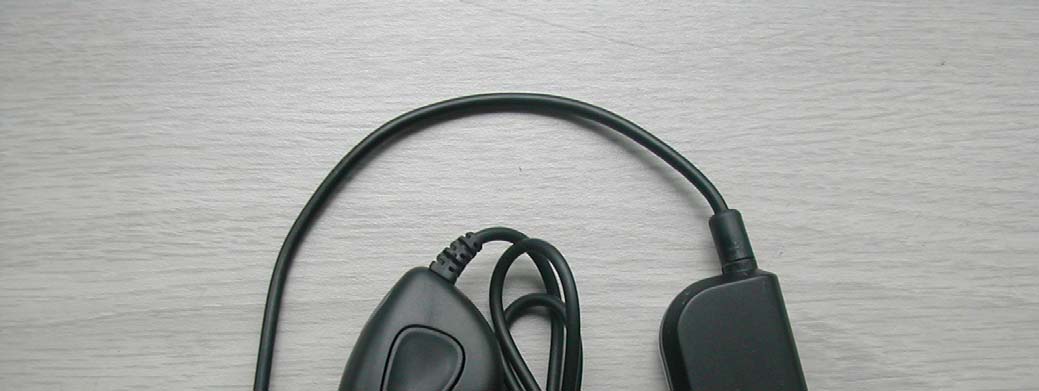
Full Band FM Transmitter - FCC ID SJD0900240G - CM Precision Technology LTD.
SJD0900240G

Full Band FM Transmitter

Sep 17, 2006

Equipment Class

DXX - Part 15 Low Power Communication Device Transmitter