SJS-380153VHPUTILITY METER DATA TRANSMITTER
Mars Company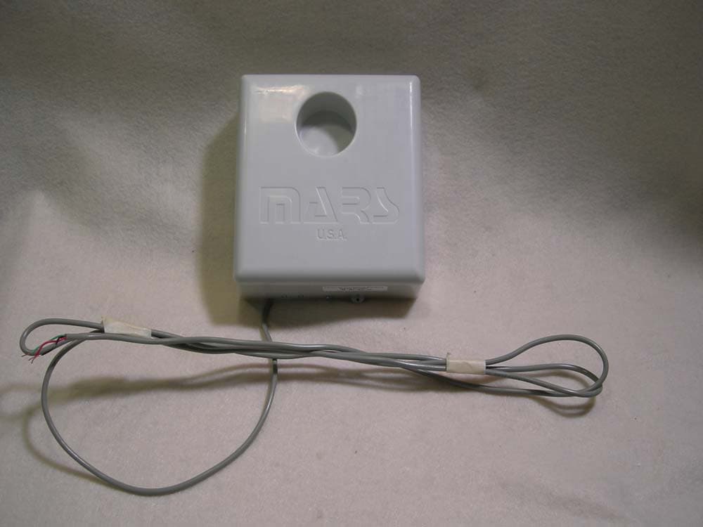
Click to zoom
Application Details
- Equipment Class
- DSS - Part 15 Spread Spectrum Transmitter
- Date of Grant
- Jan 23, 2008
- Application Purpose
- Original Equipment
- Date of Application
- Jan 22, 2008
- Equipment Note
- UTILITY METER DATA TRANSMITTER
- Frequency Range
- 905.00000000 - 925.00000000
- Company
- Mars Company
- Country
- United States
Documents & Files
Document Text
Text extracted from the exhibit documents filed with the FCC. Open a document above to read the original.
Users Manual
5015 B.U. Bowman Drive Buford, GA 30518 USA Voice: 770-831-8048 Fax: 770-831-8598 Certification Test Report Frequency Hopping Spread Spectrum Transmitter FCC ID: SJS-380153VHP IC: 5379A-380153VHP FCC Rule Part: 15.247 IC Radio Standards Specification: RSS-210 ACS Report Number: 07-0290 - 15C Manufacturer: MARS Company Model: 380135VHP, 380129VHP Installation Guide MARS SmartRadio Installation Guide To ensure proper connection and resistance to water intrusion a waterproof butt splice is required to connect the SmartTransmitter to the meter register. The recommended type of connector is a Scotchlok™ connector. This type of connector is ideal because it provides a good mechanical connection of the wires and a waterproofing gel that inhibits water ingress. This device is designed to be installed in a meter pit at or below ground level. Professional installation by factory trained personnel is required for proper use and reliable communication. Meter Connection Table Manufacturer Radio Red Radio Green Radio Black Sensus Encoder R Encoder G Encoder B Hersey Encoder R Encoder G Encoder B Neptune Encoder B Encoder R Encoder G A MCO / ABB Scancoder Encoder G Encoder R Encoder B AMCO InVision Encoder B Encoder R Encoder Shld Severn Trent Terminal 1 Terminal 3 Terminal 5 Severn Trent - Generation 2 Encoder R Encoder G Encoder B Badger RTR N/C Red Black Installation Steps 1. Refer to the table above for wiring color codes. 2. While holding the Scotchlok™ connector with the button facing down, insert un-stripped wires fully into connector. 3. Once seated, use a crimper and firmly squeeze the connector until you hear a snap and gel seeps out of the end of the connector. 4. Repeat steps 1-3 for the other two pair of wires and test to ensure the Smart Transmitter is transmitting properly. Information to the User FCC Class B: “NOTE: This equipment has been tested and found to comply with the limits for a Class B digital device, pursuant to Part 15 of the FCC Rules. These limits are designed to provide reasonable protection against harmful interference in a residential installation. This equipment generates, uses, and can radiate radio frequency energy and, if not installed and used in accordance with the instructions, may cause harmful interference to radio communications. However, there is no guarantee that interference will not occur in a particular installation. If this equipment does cause harmful interference to radio or television reception, which can be determined by turning the equipment off and on, the user is encouraged to try to correct the interference by one or more of the following measures: • Reorient or relocate the receiving antenna. • Increase the separation between the equipment and receiver. • Connect the equipment into an outlet on a circuit different from that to which the receiver is connected. • Consult the dealer or an experienced radio/TV technician for help.” Warning: Changes or modifications to this device not expressly approved by MARS Company could void the user’s authority to operate the equipment. RF Exposure: “This equipment complies with FCC radiation exposure limits set forth for an uncontrolled environment. This equipment should be installed and operated with minimum distance 20cm between the radiator and your body. This transmitter must not be co-located or operating in conjunction with any other antenna or transmitter.” Industry Canada All Equipment: This Class B digital apparatus meets all requirements of the Canadian Interference Causing Equipment Regulations. Operation is subject to the following two conditions: (1) this device may not cause harmful interference, and (2) this device must accept any interference received, including interference that may cause undesired operation. Cet appareillage numérique de la classe B répond à toutes les exigences de l'interférence canadienn e causant des règlements d'équipement. L'opération est sujette aux deux conditions suivantes: (1) ce dispositif peut ne pas causer l'interférence nocive, et (2) ce dispositif doit accepter n'importe quelle interférence reçue, y compris l'interférence qui peut causer l'opération peu désirée. MARS SmartTransmitter Programming Guide Programming of the MARS SmartTransmitter is performed using a SmartReader probe loaded with the SmartTransmitter programming software. Parameters are programmed into the SmartTransmitter by selecting options on a menu driven application and holding the SmartReader up to an inductive coil in the SmartTransmitter. Steps for programming SmartTransmitter: 1. On the SmartReader, select “MARS Radio Setup” and press <Enter> 2. Type in assigned password and press <Enter> 3. Press <F1> to retrieve the current settings from the SmartTransmitter. Hold the SmartReader nozzle up to the SmartTransmitter (where indicated above), pull the trigger and release then continue to hold SmartReader in this position until you hear a tone emit from the SmartReader. Displayed on the screen will be the current parameters of the SmartTransmitter. 4. Select the parameter you wish to change and press <Enter>. 5. You will then be prompted to make your selection or enter a numerical value for the parameter. After making your selection, press <Enter> and then <Exit> to return to the “MARS Radio Set up” parameter menu. If you have enter ed a numerical value, after you press <Enter> you will automatically be returned to the parameter menu. An * will designate a parameter that you have just entered needs to be programmed into the SmartTransmitter. 6. To send your desired parameters to the SmartTransmitter, press <F6> and hold the SmartReader nozzle up to the SmartTransmitter, Inductive coil pull the trigger and continue to hold in this position until you hear a tone emit from the SmartReader. You will then be returned to the parameter menu and your new settings will now be displayed. 7. Once all your parameters have been set , you can now turn the SmartTransmitter on. In the same manner y ou program …
Text truncated - open the document above for the full version.
Cover Letter(s)
A SUBSIDIARY OF FLOYD S. SALSER, JR. & ASSOCIATES December 21, 2007 Federal Communications Commission P.O. Box 429 Columbia, MD 21045 Gentlemen: I hereby appoint Kirby Monroe of Advanced Compliance Solutions, Inc. to act as our agent in the preparation of an application for equipment authorization of MARS SmartTransmitter model 380129VHP under Part 15 of the FCC Rules and Regulations. I certify that all exhibits contained within this filing properly describe the device or system for which authorization is sought, that the information described in the User's Manual will be provided with each item manufactured or distributed by the applicant, and that the labels described in the filing will be affixed to each item manufactured or distributed by the applicant. I further certify that appropriate arrangements have been made to assure that production units of this equipment bearing the name and FCC IDENTIFIER listed in this application will continue to comply with the Commission's requirements. I further certify by signature below that no party (per 47 CFR 1.2002(b)) to the application is subject to a denial of Federal benefits, including FCC benefits, pursuant to Section 5301 of the Anti-Drug Abuse Act of 1988, 21 U.S.C. 853(a). This appointment also includes the authority to complete FCC Form 731 on our behalf and sign the application as an authorized agent. Sincerely, Floyd S. Salser, Jr. CEO MARS Company Phone: 352.694.7195 / 800.782.5268 Fax: 352.694.7397 Email: [email protected] www.marswater.com A SUBSIDIARY OF FLOYD S. SALSER, JR. & ASSOCIATES December 21, 2007 Federal Communications Commission P.O. Box 429 Columbia, MD 21045 Gentlemen: I hereby appoint Kirby Monroe of Advanced Compliance Solutions, Inc. to act as our agent in the preparation of an application for equipment authorization of MARS SmartTransmitter model 380135VHP under Part 15 of the FCC Rules and Regulations. I certify that all exhibits contained within this filing properly describe the device or system for which authorization is sought, that the information described in the User's Manual will be provided with each item manufactured or distributed by the applicant, and that the labels described in the filing will be affixed to each item manufactured or distributed by the applicant. I further certify that appropriate arrangements have been made to assure that production units of this equipment bearing the name and FCC IDENTIFIER listed in this application will continue to comply with the Commission's requirements. I further certify by signature below that no party (per 47 CFR 1.2002(b)) to the application is subject to a denial of Federal benefits, including FCC benefits, pursuant to Section 5301 of the Anti-Drug Abuse Act of 1988, 21 U.S.C. 853(a). This appointment also includes the authority to complete FCC Form 731 on our behalf and sign the application as an authorized agent. Sincerely, Floyd S. Salser, Jr. CEO MARS Company Phone: 352.694.7195 / 800.782.5268 Fax: 352.694.7397 Email: [email protected] www.marswater.com
Cover Letter(s)
A SUBSIDIARY OF FLOYD S. SALSER, JR. & ASSOCIATES December 21, 2007 Federal Communications Commission Equipment Authorization Branch 7435 Oakland Mills Road Columbia, MD 21046 Gentlemen: MARS Company respectfully requests confidentiality of certain materials provided with the submission of the MARS SmartTransmitter Models 380129VHP and 380135VHP under FCC ID: SJS-380153VHP in accordance with FCC Regulations 0.459. The confidentiality request applies to the schematic diagrams, detailed block diagrams, detailed operational descriptions, and parts lists contained in this filing and included in the following files. 07-0290 – Schematics.pdf 07-0290 – Parts List.pdf 07-0290 – System Block Diagram.pdf 07-0290 – Theory of Operation.pdf The MARS SmartTransmitter Models 380129VHP and 380135VHP have been developed at considerable effort and expense by MARS Company. These items are considered as Trade Secrets and therefore public access to the proprietary material could possibly result in duplication of equipment that could severely damage the company’s business advantage. I appreciate your assistance in this matter. Sincerely, Floyd S. Salser, Jr. CEO MARS Company Phone: 352.694.7195 / 800.782.5268 Fax: 352.694.7397 Email: [email protected] www.marswater.com
External Photos
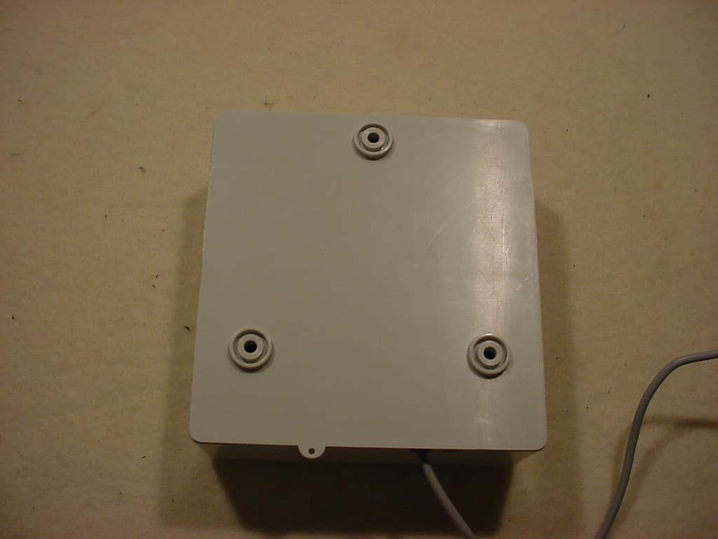
5015 B.U. Bowman Drive Buford, GA 30518 USA Voice: 770-831-8048 Fax: 770-831-8598 Certification Test Report Frequency Hopping Spread Spectrum Transmitter FCC ID: SJS-380153VHP IC: 5379A-380153VHP FCC Rule Part: 15.247 IC Radio Standards Specification: RSS-210 ACS Report Number: 07-0290 - 15C Manufacturer: MARS Company Model: 380135VHP, 380129VHP External Photos Model: 380135VHP, 380129VHP FCC ID: SJS-380153VHP IC: 5379A-380153VHP ACS Report: 07-0290 – 15C Advanced Compliance Solutions Page 2 Figure 1: Wall Mount - External Overview Model: 380135VHP, 380129VHP FCC ID: SJS-380153VHP IC: 5379A-380153VHP ACS Report: 07-0290 – 15C Advanced Compliance Solutions Page 3 Figure 2: Wall Mount - Front View Model: 380135VHP, 380129VHP FCC ID: SJS-380153VHP IC: 5379A-380153VHP ACS Report: 07-0290 – 15C Advanced Compliance Solutions Page 4 Figure 3: Wall Mount - Back View Model: 380135VHP, 380129VHP FCC ID: SJS-380153VHP IC: 5379A-380153VHP ACS Report: 07-0290 – 15C Advanced Compliance Solutions Page 5 Figure 4: Wall Mount - Top View Model: 380135VHP, 380129VHP FCC ID: SJS-380153VHP IC: 5379A-380153VHP ACS Report: 07-0290 – 15C Advanced Compliance Solutions Page 6 Figure 5: Wall Mount - Bottom View Model: 380135VHP, 380129VHP FCC ID: SJS-380153VHP IC: 5379A-380153VHP ACS Report: 07-0290 – 15C Advanced Compliance Solutions Page 7 Figure 6: Wall Mount - Side 1 View Model: 380135VHP, 380129VHP FCC ID: SJS-380153VHP IC: 5379A-380153VHP ACS Report: 07-0290 – 15C Advanced Compliance Solutions Page 8 Figure 7: Wall Mount - Side 2 View Model: 380135VHP, 380129VHP FCC ID: SJS-380153VHP IC: 5379A-380153VHP ACS Report: 07-0290 – 15C Advanced Compliance Solutions Page 9 Figure 8: Pit Mount – External Overview Model: 380135VHP, 380129VHP FCC ID: SJS-380153VHP IC: 5379A-380153VHP ACS Report: 07-0290 – 15C Advanced Compliance Solutions Page 10 Figure 9: Pit Mount – Top View Model: 380135VHP, 380129VHP FCC ID: SJS-380153VHP IC: 5379A-380153VHP ACS Report: 07-0290 – 15C Advanced Compliance Solutions Page 11 Figure 10: Pit Mount – Bottom View Model: 380135VHP, 380129VHP FCC ID: SJS-380153VHP IC: 5379A-380153VHP ACS Report: 07-0290 – 15C Advanced Compliance Solutions Page 12 Figure 11: Pit Mount – Side View 1 Model: 380135VHP, 380129VHP FCC ID: SJS-380153VHP IC: 5379A-380153VHP ACS Report: 07-0290 – 15C Advanced Compliance Solutions Page 13 Figure 12: Pit Mount – Side View 2
ID Label/Location Info
5015 B.U. Bowman Drive Buford, GA 30518 USA Voice: 770-831-8048 Fax: 770-831-8598 Certification Test Report Frequency Hopping Spread Spectrum Transmitter FCC ID: SJS-380153VHP IC: 5379A-380153VHP FCC Rule Part: 15.247 IC Radio Standards Specification: RSS-210 ACS Report Number: 07-0290 - 15C Manufacturer: MARS Company Model: 380135VHP, 380129VHP Label Information A SUBSIDIARY OF FLOYD S. SALSER, JR. & ASSOCIATES December 12, 2007 Advanced Compliance Solutions, Inc. 5015 B.U. Bowman Drive Buford, GA 30518 Subject: Label Specifications and Placement for MARS SmartTransmitter Model # 380129VHP To Whom It May Concern: Actual size of the label is 1 and 1/2 inches wide by 1 and 1/4 inches tall and will be placed on the bottom half of the product, as shown below. Thank you, Chris Mastic AMR Product Manager MARS Company Phone: 352.694.7195 / 800.782.5268 Fax: 352.694.7397 Email: [email protected] www.marswater.com A SUBSIDIARY OF FLOYD S. SALSER, JR. & ASSOCIATES October 4, 2007 Advanced Compliance Solutions, Inc. 5015 B.U. Bowman Drive Buford, GA 30518 Subject: Label Specifications and Placement for MARS SmartTransmitter Model # 380135VHP To Whom It May Concern: Actual size of the label is 1 and 1/2 inches wide by 1 and 1/4 inches tall and will be placed on the center of the rear of the product, as shown below. Thank you, Chris Mastic AMR Products Manager MARS Company Phone: 352.694.7195 / 800.782.5268 Fax: 352.694.7397 Email: [email protected] www.marswater.com
Internal Photos
5015 B.U. Bowman Drive Buford, GA 30518 USA Voice: 770-831-8048 Fax: 770-831-8598 Certification Test Report Frequency Hopping Spread Spectrum Transmitter FCC ID: SJS-380153VHP IC: 5379A-380153VHP FCC Rule Part: 15.247 IC Radio Standards Specification: RSS-210 ACS Report Number: 07-0290 - 15C Manufacturer: MARS Company Model: 380135VHP, 380129VHP Internal Photos Model: 380135VHP, 380129VHP FCC ID: SJS-380153VHP IC: 5379A-380153VHP ACS Report: 07-0290 – 15C Advanced Compliance Solutions Page 2 Figure 1: Wall Mount – PCB Internal Overview Model: 380135VHP, 380129VHP FCC ID: SJS-380153VHP IC: 5379A-380153VHP ACS Report: 07-0290 – 15C Advanced Compliance Solutions Page 3 Figure 2: Wall Mount – Battery Location Model: 380135VHP, 380129VHP FCC ID: SJS-380153VHP IC: 5379A-380153VHP ACS Report: 07-0290 – 15C Advanced Compliance Solutions Page 4 Figure 3: Pit Mount – PCB Internal Overview Model: 380135VHP, 380129VHP FCC ID: SJS-380153VHP IC: 5379A-380153VHP ACS Report: 07-0290 – 15C Advanced Compliance Solutions Page 5 Figure 4: Pit Mount – Battery Location Model: 380135VHP, 380129VHP FCC ID: SJS-380153VHP IC: 5379A-380153VHP ACS Report: 07-0290 – 15C Advanced Compliance Solutions Page 6 Figure 5: PCB with Battery Attached Model: 380135VHP, 380129VHP FCC ID: SJS-380153VHP IC: 5379A-380153VHP ACS Report: 07-0290 – 15C Advanced Compliance Solutions Page 7 Figure 6: PCB– Top View Model: 380135VHP, 380129VHP FCC ID: SJS-380153VHP IC: 5379A-380153VHP ACS Report: 07-0290 – 15C Advanced Compliance Solutions Page 8 Figure 7: PCB – Bottom View
RF Exposure Info
5015 B.U. Bowman Drive Buford, GA 30518 USA Voice: 770-831-8048 Fax: 770-831-8598 Certification Test Report Frequency Hopping Spread Spectrum Transmitter FCC ID: SJS-380153VHP IC: 5379A-380153VHP FCC Rule Part: 15.247 IC Radio Standards Specification: RSS-210 ACS Report Number: 07-0290 - 15C Manufacturer: MARS Company Model: 380135VHP, 380129VHP RF Exposure Model: 380135VHP, 380129VHP FCC ID: SJS-380153VHP IC: 5379A-380153VHP ACS Report: 07-0290 – 15C Advanced Compliance Solutions Page 2 General Information: Applicant: Mars Company ACS Project: 07-0290 Device Category: Mobile Environment: General Population/Uncontrolled Exposure Technical Information: Antenna Type(s): Quarter-Wave Whip Antenna Gain: 2 dBi Transmitter Conducted Power: 29.85dBm Maximum System EIRP: 31.85 dBm Exposure Conditions: Greater than 20 centimeters MPE Calculation The Power Density (mW/cm 2 ) is calculated as follows: S = 2 4R PG π Where: S = power density (in appropriate units, e.g. mW/cm2) P = power input to the antenna (in appropriate units, e.g., mW) G = power gain of the antenna in the direction of interest relative to an isotropic radiator R = distance to the center of radiation of the antenna (appropriate units, e.g., cm) MPE Calculator for Mobile Equipment Limits for General Population/Uncontrolled Exposure* 90529.850.60966.0521.585 200.305 Power Density (mW/cm^2) Distance (cm) Transmit Frequency (MHz) Radio Power (dBm) Power Density Limit (mW/Cm2) Radio Power (mW) Antenna Gain (dBi) Antenna Gain (mW eq.) Installation Guidelines The installation manual should contain text similar to the following advising how to install the equipment to maintain compliance with the FCC RF exposure requirements: RF Exposure In accordance with FCC requirements of human exposure to radio frequency fields, the radiating element shall be installed such that a minimum separation distance of 20 centimeters will be maintained. Conclusion This device complies with the MPE requirements by providing adequate separation between the device, any radiating structure and the general population.
Test Report
5015 B.U. Bowman Drive Buford, GA 30518 USA Voice: 770-831-8048 Fax: 770-831-8598 Certification Test Report Frequency Hopping Spread Spectrum Transmitter FCC ID: SJS-380153VHP IC: 5379A-380153VHP FCC Rule Part: 15.247 IC Radio Standards Specification: RSS-210 ACS Report Number: 07-0290 - 15C Manufacturer: MARS Company Model: 380135VHP, 380129VHP Test Begin Date: September 12, 2007 Test End Date: September 27, 2007 Report Issue Date: December 17, 2007 FOR THE SCOPE OF ACCREDITATION UNDER LAB Code 200612-0 This report is not be used to claim certification, approval, or endorsement by NVLAP, NIST or any government agency. Prepared by: Reviewed by: J. Kirby Munroe Manager Wireless Certifications ACS, Inc. R. Sam Wismer Engineering Manager ACS, Inc. This test report shall not be reproduced except in full. This report may be reproduced in part with prior written consent of ACS, Inc. The results contained in this report are representative of the sample(s) submitted for evaluation. This report contains 24 pages 5015 B.U. Bowman Drive Buford, GA 30518 USA Voice: 770-831-8048 Fax: 770-831-8598 Table of Contents 1.0 General 3 1.1 Purpose 3 1.2 Product Description 3 1.2.1 General 3 1.2.2 Intended Use 3 1.3 Test Methodology and Considerations 3 2.0 Test Facilities 4 2.1 Location 4 2.2 Laboratory Accreditations/Recognitions/Certifications 4 2.3 Radiated Emissions Test Site Description 5 2.3.1 Semi-Anechoic Chamber Test Site 5 2.3.2 Open Area Tests Site (OATS) 6 2.4 Conducted Emissions Test Site Description 7 3.0 Applicable Standards and References 7 4.0 List of Test Equipment 8 5.0 Support Equipment 9 6.0 EUT Setup Block Diagram 9 7.0 Summary of Tests 10 7.1 Antenna Requirement 10 7.2 Power Line Conducted Emissions 10 7.2.1 Test Methodology 10 7.2.2 Test Results 10 7.3 Radiated Emissions (Unintentional Radiation) 10 7.3.1 Test Methodology 10 7.3.2 Test Results 10 7.4 Peak Output Power 11 7.4.1 Test Methodology 11 7.4.2 Test Results 11 7.5 Channel Usage 13 7.5.1 Carrier Frequency Separation 13 7.5.1.1 Test Methodology 13 7.5.1.2 Test Results 13 7.5.2 Number of Hopping Channels 14 7.5.3 Channel Dwell Time 15 7.5.3.1 Test Methodology 15 7.5.3.2 Test Results 15 7.5.4 20dB Bandwidth 16 7.5.4.1 Test Methodology 16 7.5.4.2 Test Results 16 7.6 Band-edge Compliance and Spurious Emissions 17 7.6.1 Band-edge Compliance of RF Conducted Emissions 17 7.6.1.1 Test Methodology 17 7.6.1.2 Test Results 17 7.6.2 RF Conducted Spurious Emissions 18 7.6.2.1 Test Methodology 18 7.6.2.2 Test Results 18 7.6.3 Radiated Spurious Emissions (Transmitter) 22 7.6.3.1 Test Methodology 22 7.6.3.2 Test Results 22 7.6.3.3 Sample Calculations 24 8.0 CONCLUSION 24 Additional Exhibits Included In Filing Internal Photographs External Photographs Test Setup Photographs Product Labeling RF Exposure – MPE Calculations Installation/Users Guide Theory of Operation BOM (Parts List) System Block Diagram Schematics Model: 380135VHP, 380129VHP FCC ID: SJS-380153VHP IC: 5379A-380153VHP ACS Report: 07-0290 – 15C Advanced Compliance Solutions Page 3 1.0 GENERAL 1.1 Purpose The purpose of this report is to demonstrate compliance with Part 15, Subpart C of the FCC’s Code of Federal Regulations and Industry Canada’s Radio Standards Specification RSS-210. 1.2 Product Description 1.2.1 General The MARS Smart Transmitter 380135VHP (Wall Mount) and 380129VHP (Pit Mount) units are intended to be used to transmit meter-reading data from a utility meter to a data-collecting device. The device operates in a ’regular transmit’ mode. The utility meter is interrogated every 15 minutes to 1 hour, and the reading taken is transmitted as described in 2 above. The unit will transmit up-to 1watt of RF power into the Antenna. The Antenna is integral to the packaging and comprises a quarter-wave-monopole with a very small ground plane regarded as having a negligible effect. The two model variants, 380135VHP (Wall Mount) and 380129VHP (Pit Mount), are electrically identical and differ only external appearance and design. Manufacturer Information: MARS Company 3925 SW 13 th Stl Ocala, FL 34477-2887 Serial Numbers: F4 (Wall mount) F5 (Pit Mount) Test Sample Condition: The EUT samples were received in working order with no visible defects. Detailed photographs of the EUT are filed separately with this filing. 1.2.2 Intended Use The units are intended to be used to transmit meter-reading data from a utility meter to a data-collecting device. 1.3 Test Methodology and Considerations To facilitate RF conducted measurements, a temporary RF connector was utilized. The test sample for RF conducted measurements was modified, by the applicant, with a temporary SMA connector. This sample was only used for RF conducted measurements and separate samples provided for radiated measurements. Each model variant was tested separately for radiated emissions and all data is presented in this report. Model: 380135VHP, 380129VHP FCC ID: SJS-380153VHP IC: 5379A-380153VHP ACS Report: 07-0290 – 15C Advanced Compliance Solutions Page 4 2.0 TEST FACILITIES 2.1 Location The radiated and conducted emissions test sites are located at the following address: Advanced Compliance Solutions 5015 B.U. Bowman Drive Buford, GA 30518 Phone: (770) 831-8048 Fax: (770) 831-8598 2.2 Laboratory Accreditations/Recognitions/Certifications The Semi-Anechoic Chamber Test Site, Open Area Test Site (OATS) and Conducted Emissions Site have been fully described, submitted to, and accepted by the FCC, Industry Canada and the Japanese Voluntary Control Council for Interference by information technology equipment. In addition, ACS is compliant to ISO 17025 as certified by the National Institute of Standards and Technology under their National Voluntary Laboratory Accreditation Program. The following certification numbers have been issued in recognition of these accreditations and certifications: FCC Registration Number: 894540 Industry Canada Lab Code: IC 4175 VCCI Member Number: 1831 VCCI OATS Registration Number R-1526 VCC…
Text truncated - open the document above for the full version.
Test Setup Photos
5015 B.U. Bowman Drive Buford, GA 30518 USA Voice: 770-831-8048 Fax: 770-831-8598 Certification Test Report Frequency Hopping Spread Spectrum Transmitter FCC ID: SJS-380153VHP IC: 5379A-380153VHP FCC Rule Part: 15.247 IC Radio Standards Specification: RSS-210 ACS Report Number: 07-0290 - 15C Manufacturer: MARS Company Model: 380135VHP, 380129VHP Test Set Up Photos Model: 380135VHP, 380129VHP FCC ID: SJS-380153VHP IC: 5379A-380153VHP ACS Report: 07-0290 – 15C Advanced Compliance Solutions Page 2 Figure 1: Intentional Radiated Emissions – Pit Unit Model: 380135VHP, 380129VHP FCC ID: SJS-380153VHP IC: 5379A-380153VHP ACS Report: 07-0290 – 15C Advanced Compliance Solutions Page 3 Figure 2: Intentional Radiated Emissions – Pit Unit Model: 380135VHP, 380129VHP FCC ID: SJS-380153VHP IC: 5379A-380153VHP ACS Report: 07-0290 – 15C Advanced Compliance Solutions Page 4 Figure 3: Intentional Radiated Emissions – Wall Unit Model: 380135VHP, 380129VHP FCC ID: SJS-380153VHP IC: 5379A-380153VHP ACS Report: 07-0290 – 15C Advanced Compliance Solutions Page 5 Figure 4: Intentional Radiated Emissions – Wall Unit Model: 380135VHP, 380129VHP FCC ID: SJS-380153VHP IC: 5379A-380153VHP ACS Report: 07-0290 – 15C Advanced Compliance Solutions Page 6 Figure 5: Unintentional Radiated Emissions – Pit Unit Model: 380135VHP, 380129VHP FCC ID: SJS-380153VHP IC: 5379A-380153VHP ACS Report: 07-0290 – 15C Advanced Compliance Solutions Page 7 Figure 6: Unintentional Radiated Emissions – Pit Unit Model: 380135VHP, 380129VHP FCC ID: SJS-380153VHP IC: 5379A-380153VHP ACS Report: 07-0290 – 15C Advanced Compliance Solutions Page 8 Figure 7: Unintentional Radiated Emissions – Wall Unit Model: 380135VHP, 380129VHP FCC ID: SJS-380153VHP IC: 5379A-380153VHP ACS Report: 07-0290 – 15C Advanced Compliance Solutions Page 9 Figure 8: Unintentional Radiated Emissions – Wall Unit
Contact Information
Applicant
Chris Mastic(Technology Development Manager)
Test Firm
Advanced Compliance Solutions, Inc.Douglas Massey
Technical Specifications
| # | Rule Parts | Frequency Range | Power Output |
|---|---|---|---|
| 1 | 15C | 905 MHz - 925 MHz | 966.00 mW |
Other Applications from Mars Company
SJS-380115WM
May 10, 2007UTILITY METER DATA TRANSMITTER
Equipment Class
DXX - Part 15 Low Power Communication Device Transmitter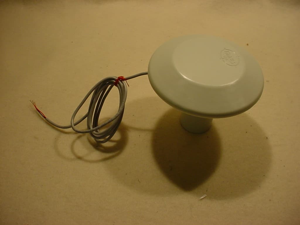
SJS-380117HP
May 10, 2007UTILITY METER DATA TRANSMITTER
Equipment Class
DXX - Part 15 Low Power Communication Device Transmitter
SJS-380112WM
Mar 06, 2007UTILITY METER DATA TRANSMITTER
Equipment Class
DXX - Part 15 Low Power Communication Device Transmitter
SJS-380111HP
Mar 04, 2007UTILITY METER DATA TRANSMITTER
Equipment Class
DXX - Part 15 Low Power Communication Device Transmitter
SJS-380101WM
Mar 22, 2006UTILITY METER DATA TRANSMITTER
Equipment Class
DXX - Part 15 Low Power Communication Device Transmitter