SJW3000-2024-15CPE WIRELESS ACCESS POINTw/ 802.11b RF MODULES
AirTegrity Wireless, Inc.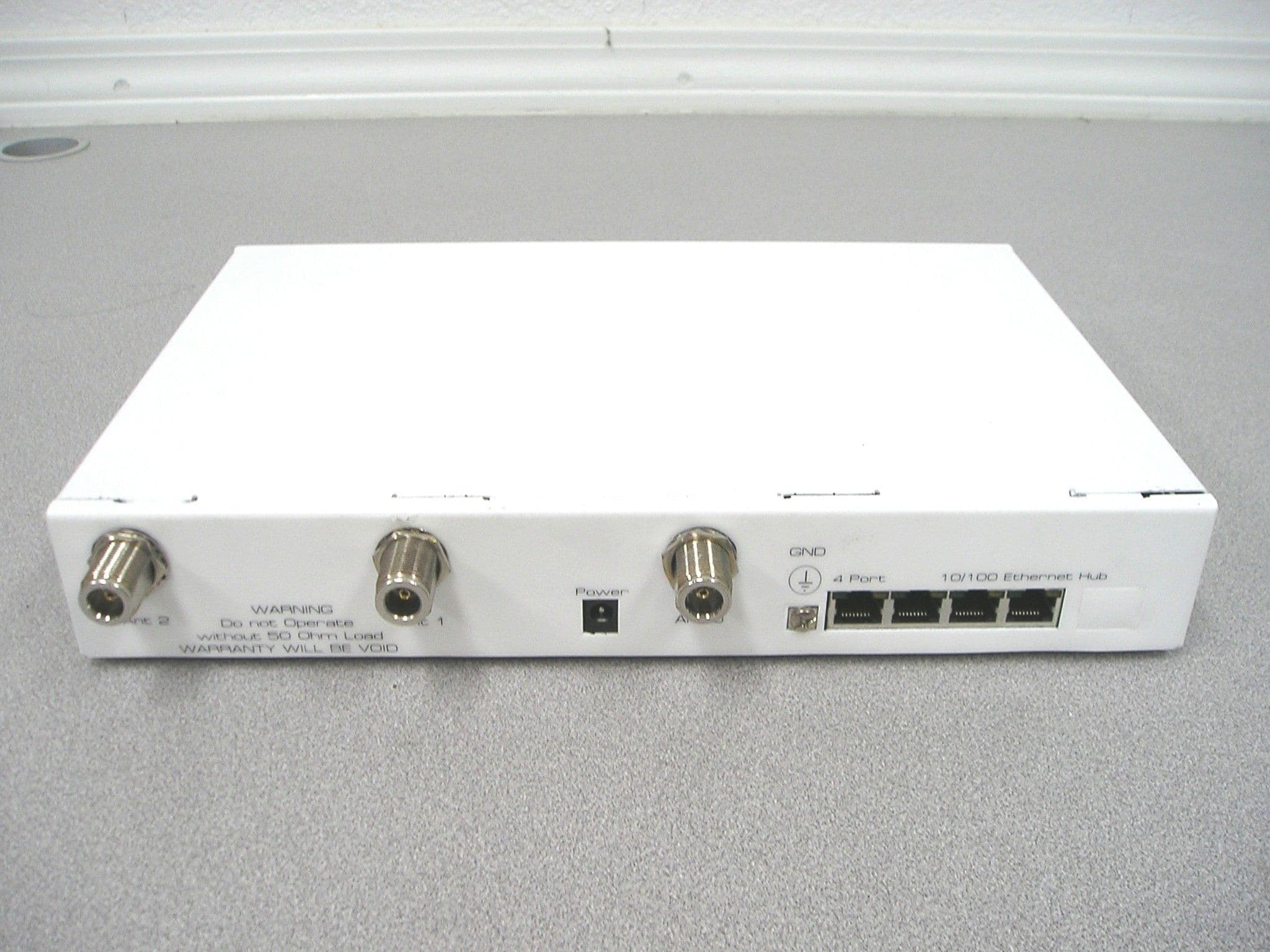
Click to zoom
Application Details
- Equipment Class
- DTS - Digital Transmission System
- Date of Grant
- Jun 19, 2005
- Application Purpose
- Original Equipment
- Date of Application
- Jun 19, 2005
- Equipment Note
- CPE WIRELESS ACCESS POINTw/ 802.11b RF MODULES
- Frequency Range
- 2412.00000000 - 2462.00000000
- Company
- AirTegrity Wireless, Inc.
- Country
- United States
Documents & Files


Document Text
Text extracted from the exhibit documents filed with the FCC. Open a document above to read the original.
Users Manual
Series 4000 Router Installation Guide Rev 4.06, 2005 March 04 Series 4000 Router Installation Guide AirTegrity Wireless, Inc. Rev 4.06, 2005 March 04 AirTegrity Headquarters AirTegrity Wireless, Inc. 276 Kingsbury Grade, Suite 206 Stateline, Nevada, 89449-5188 USA AirTegrity Mailing Address AirTegrity Wireless, Inc. P.O Box 5188 Stateline, Nevada, 89449-5188 USA Copyright© 2004, 2005 by AirTegrity Wireless, Inc. All rights reserved. No part of this book or manual may be reproduced or transmitted in any form or by any means, electronic or mechanical, including photocopying, recording, or by any information storage and retrieval system, without the express written permission from the AirTegrity Wireless, Inc., except for the inclusion of a brief quotation(s) used in a review. Frontmatter Series 4000 Router Installation Guide iii Warning and Disclaimer This book is designed to provide information about the Series 4000 Router Product(s). Every effort has been made to make this book as complete and as accurate as possible, but no warranty or fitness is implied. The information is provided on an “as is” basis. The author, AirTegrity Wireless, Inc., shall have neither liability nor responsibility to any person or entity with respect to any loss or damage arising from the information contained in this book or from the use of equipment or software that might accompany it. The opinions expressed in this book are not necessarily those of AirTegrity Wireless, Inc. Regulatory Information Federal Communication Commission Information FCC Statement This device complies with Part 15 rules. Operation is subject to the following two conditions: 1.This device may not cause harmful interference, and 2.This device must accept any interference received, including interference that may cause undesired operation. This equipment has been tested and found to comply with the limits of a Class B digital device, pursuant to Part 15 of the FCC Rules. These limits are designed to provide reasonable protection against harmful interference when the equipment is operated in a residential environment. This equipment generates, uses, and radiates radio frequency energy, and if not installed and used in accordance with the instructions, may cause harmful interference. However, there is no guarantee that interference will not occur. If this equipment does cause interference to radio or television reception, which can be determined by turning the equipment off and on, the user is encouraged to correct the interference by one of the following measures: •Reorient or relocate the receiving antenna. •Increase separation between the equipment and receiver. •Connect the equipment to an outlet on a circuit different from which the receiver is connected. •Consult the dealer or an experienced radio/TV technician. CAUTION: Changes or modifications not expressly approved by the party responsible for compliance could void the user's authority to operate the equipment. Model:4000 series with 2024-15 FCC ID:SJW-4000-2024-15 Manufacturer:AirTegrity Wireless, Inc. 276 Kingsbury Grade, Suite 206 P.O. Box 5188 Stateline NV 89449-5188, USA Frontmatter Series 4000 Router Installation Guide iv Declaration of Conformity for the R&TTE Directive 1999/5/EC English: This equipment is in compliance with the essential requirements and other relevant provisions of Directive 1999/5/EC. Deutsch: Dieses Gerät entspricht den grundlegenden Anforderungen und den weiteren entsprecheneden Vorgaben der Richtlinie 1999/5/EU. Français: Cet appareil est conforme aux exigencies essentialles et aux autres dispositions pertinantes de la Directive 1999/5/EC. CE Declaration of Conformity We, AirTegrity Wireless Inc., of 276 Kingsbury Grade, Suite 206, Stateline Nevada, 89449-5188, USA, declare under our sole responsibility that the model 4000 series installed with the 2024-06 radio card to which this declaration relates is in conformity with the following standards and/or other normative documents: EN 300 328-1 EN 300 328-2 EN 301 489-1 EN 301 489-3 EN 301 489-17 EN 60950 We, AirTegrity Wireless Inc., hereby declare that this product is in compliance with the essential requirements and other relevant provisions of Directive 1999/5/EC. This product can be used in the following countries: UK, Germany, and France. Antennas Tested The following antennas were tested with the 4000 installed with a 2024-15 radio: Trademark Acknowledgments All terms mentioned in this book that are known trademarks or service marks have been appropriately capitalized. AirTegrity Wireless, Inc. cannot attest to the accuracy of this information. Use of a term in this book should not be regarded as affecting the validity of any trademark or service mark. Antenna Type Manufacturer Model Number Antenna Gain Directional PanelTil-Tek TA-2408 17 dBi Omni HyperLink Technologies HG2415U-PRO 15 dBi Yagi Poynting Group YAGI-A0005 13 dBi Frontmatter Series 4000 Router Installation Guide v Readers’ Feedback At AirTegrity Wireless, Inc., our goal is to create in-depth technical documentation of the highest quality and value. Each book is crafted with care and precision, involving many hours of research and the collaboration of many members from the development teams. Readers' feedback is actively sought to help us improve on future revisions and publications. If there are any items that you feel are in error or areas that could be altered to better suit your needs, you can contact us through e-mail at techpubs@ airtegrity.com. Please be sure to include the title and revision of the document. Series 4000 Router Installation Guide vi AirTegrity Limited Warranty Limited Warranty Hardware. AirTegrity Wireless, Inc. (“AirTegrity“), warrants that commencing from the date of delivery to Customer (but in case of resale by an AirTegrity reseller, commencing not more than ninety (90) days after original shipment by AirTegrity), and continuing for a period of the longer of (a) ninety (90) days or (b) the period set forth i…
Text truncated - open the document above for the full version.
Users Manual
ITC Engineering Services Over 20 years experience in Compliance Testing and Engineering Consulting Services —————————————————————————————————————————————————————— ————————————————EN 45001, NVLAP and VCCI Accredited Laboratory———————————————— 9959 Calaveras Road, Box 543, Sunol, CA 94586-0543 Phone: (925) 862-2944 • (888) 336-7625 • Fax: (925) 862-9013 E-mail: [email protected] • Web: www.itcemc.com Mr.Frank DeNuzzo Timco Engineering Inc. 849 NW State Road 45, Newberry, Florida 32669. SUBJECT: 20cm RF Exposure Statement. The users’ manual submitted with the application is a draft copy. The final version of the users’ manual will contain the 20cm RF exposure statement. Sincerely, Femi Ojo ITC Engineering Services.
ID Label/Location Info
This device complies with FCC Rules Part 15. Operation is subject to the following two conditions: (1) This device may not cause harmful interference, and (2) This device must accept an y interference received, including interference that may cause undesired operation. Ser ies Subscrib er Sta tion CPE AirTegrity Wireless, Inc. 276 Kingsbury Grade, Suite 206 P.O. Box 5188 Stateline, NV 89449-5188 (775) 588-8800 www.airtegrity.com MADE IN USA Model: 4000 FCC ID: SJW-4000-2024-15
ID Label/Location Info
ITC Engineering Services Over 20 years experience in Compliance Testing and Engineering Consulting Services —————————————————————————————————————————————————————— ————————————————EN 45001, NVLAP and VCCI Accredited Laboratory———————————————— 9959 Calaveras Road, Box 543, Sunol, CA 94586-0543 Phone: (925) 862-2944 • (888) 336-7625 • Fax: (925) 862-9013 E-mail: [email protected] • Web: www.itcemc.com Timco Engineering Inc. 849 NW State Road 45, Newberry, Florida 32669. SUBJECT: Label location for Air Tegrity units 3000 and 4000. The label location for 3000 unit is on the side of the unit. The label location for 4000 unit is on the bottom of the unit. Thank you, Femi Ojo ITC Engineering Services.
Operational Description
ITC Engineering Services Over 20 years experience in Compliance Testing and Engineering Consulting Services —————————————————————————————————————————————————————— ————————————————EN 45001, NVLAP and VCCI Accredited Laboratory———————————————— 9959 Calaveras Road, Box 543, Sunol, CA 94586-0543 Phone: (925) 862-2944 • (888) 336-7625 • Fax: (925) 862-9013 E-mail: [email protected] • Web: www.itcemc.com Timco Engineering Inc. 849 NW State Road 45, Newberry, Florida 32669. SUBJECT: Operational description for Air Tegrity units 3000 and 4000. 3000: CPE wireless access point with two 802.11b RF modules. 4000: Base station, wireless access point and edge router, w/one Ethernet card and two 802.11b RF modules. Femi Ojo ITC Engineering Services.
RF Exposure Info
RF SAFETY EXPOSURE PER FCC REQUIREMENT The limit for MPE per FCC 47CFR 1.1307 is 1.0mW/cm 2 (Power density).The MPE range is calculated as shown in the equation below. P D = ( P t G t /4πR 2 ) P D = Power density G t = Antenna gain P t = Peak power R= Range P D = 1.0mW/ cm 2 P t = 103.75mW Antenna gain = 22dBi (14.67 numerical value) for Parabolic Antenna 17dBi (11.33 numerical value) for Flat Panel Antenna. 15dBi (10.0 numerical value) for Omni Antenna. 13dBi (8.7 numerical value) for Yaggi Antenna. With 22dBi Antenna gain 1.0 = (103.75 x 14.67) / 4πR 2 R = [(103.75 x 14.67) / 4π)] ½ = 11.0cm With 17dBi Antenna gain R = [(103.75 x 11.33) / 4π)] ½ = 9.7cm With 15dBi Antenna gain R = [(103.75 x 10.0) / 4π)] ½ = 9.0cm With 13dBi Antenna gain R = [(103.75 x 10.0) / 4π)] ½ = 8.5cm. The maximum calculated MPE distance (R) is shown for each antenna.The installation instruction shall indicate that at least the MPE distance + 2cm margin separation shall be provided between antennas and the people. Prepared by Reviewed by Femi Ojo, Michael Gbadebo, P.E, Chief Engineer. Test Engineer (California License # 11303)
Schematics
AA BB CC DD EE 4 4 3 3 2 2 1 1 AR4000 - Élan520Motherboard - 3 PMC PCB LAYOUT DESIGN NOTES2. Note Bypass capacitors on various pages and place themnear listed P/S lines for the devices3. SDRAM Build options include support for 1M x 16 and 4M x16 parts. These may overlap in layout as population will beone set or the other. Refer to SDRAM page for more detailsand specific layout instructions4. IDE Connector to be mounted on bottom of PCB towards BackRHS5. Refer to design guide for information regarding thelayout of PCI signals. Very Critical. Also refer to PCIinterface page for more info. DESCRIPTION 05/29/01 Revision 0.2D Updated U28 to GND from DGND. Revision 0.2F Created GWPRRW 05/29/01 Updated grounds 06/07/02 Revision 0.1.M Updated speaker footpr int. RRW Added R40 short for VCC12 and +12V 09/23/01DATE10/05/01 GWP Revision 0.1 RRWGWP Revision 0.2E 10/11/01 Updated footprint names and pin n umbers. Added Partnumbers to comp onents Revision 0.2G REVISION 09/27/01 RRW Revision 0.2 WHO 1. Place 33 Ohm Resistors on PCI Address BUS close to theElan520Several PCI lines have pull up resistors. If layout permitsplace these together in groups and then modify schematic touse resistor packsBUILD OPTIONS1. Engineering Build with debug headers2. Production 4031 - Single Port Ethernet4. Production 4500 Series - Single Port Ethenet + IDE3. Production 4034 - Quad Four Port Ethernet Revision E 1 08/26/03 GWP Design Changes from preproduct ion run GWP Revisions E2throuh E21 01/06/04 1. Make Part Number and Build Option fields visible. 2. Remove the following components; R26, R28, R56, R74, R204, R205, R206, R208, R209, R 210, R211, R212, 216 3. DNP the following components; CT41 4. 12 Volt power supply rail on schematic must come from one source. Feed Power supply entry points, Power jack and Molex Rack P/S to this feed resistor and then to the 12V plane, traces. R14 was previously connected to the wrong plane; check this when redr awing this section. 5. Change the Power Supply connector to use a locking type connector. Get d etails from Dave. 6. +5V net is tied to +12V plane. Remove c onnection 7. R220 change to 0R.8. Select alternative LAN So lution 9. Select correct resistor value to drive LEDs for LAN. Ensure correct or both single and four port models. 10. Pinouts for single RJ45 have the incorrect polarity for the LEDs 11. Add 3 0R resistors as a replacement for the switch S1 and RN2. 12. Check all connections on PMC connectors are correct with current specification. Know errors; BUSMODE 2 is connected to +3 not +5. Naming of connectors is not according to standard. 13. Make all parts associated with -5V DNP in both versions. 14. Remove all ISA BUS related components from schematic. This will make the routing of the motherboard significantly easier. Confirm removal of components on development board. 15. Change SDCLK (SDRAM) to split and then go to two resistors to f eed SDRAM clocks 16. Convert the PCI to a series ter mination 17. Check to see that correct decoupling of the 50Mhz Oscil lator is used. 18. Review Power Supply as most app ropriate 19. Main crystal used for 33.333MHz clock is multi-foot print - switch to dedicated footprint to avoid confusion on PCB layout 20. Remove all buffers not n eeded. 21. Review any resisters that can be converted to res istor packs. 22. Add facility for common mode chokes on schematic for power supply inputs. To be used if emissions are seen as a problem. 23. Check for removal of ALL ISA lines and Clocks. 24. Review crystal opti ons. 25. Ensure Ground Plane is separate from Chassis Ground. 1. Update CFG strap population options to reflect 16-bit flash bus. 2. Fix part numbers of R28, R38, R66, R78, R100, C19, C21 for 0603 package. 3. Fix debug strap build options, so option 1 gets a DIP switch, and the ot hers disable JTAG. 4. Everything on the 4-port switch page, and the 1.8V power supply, only loaded on 4-port build option. 5. Nothing on the 1-port PHY or I/F pages gets loaded on the 4-port build option. 6. The 4-port build option has the front-panel ethernet LEDs driven by the M AC, via R172,R173. 01/07/04 MCG Revision E22 Revision 2.1.23 JMB 02/15/04 2.) Fixed page numbers on block d iagram. 1.) Fixed/revised 5VO and 3V3 Power S upplies. Revision 2.1.24 GWP 02/16/04 1. Fixed connection of power to L1. 2. Added part numbers.3. Fixed reversed part No 3904/3906 pair on Bat Sense input 4. Moved many items back on grid and ran DRC 5. Change Main OSC power to VCC_CPU and DNP to pull down to ground, changed in l ine resitor to 220R 6. Added Ferrite to VCC_ANALOG to pr ocessor 1. Added Ferrite to P1 conne ctions 3/15/04 DRK Revision 2.1.29 Revision History 2.1.29 AirRunner AR4030 - AMD Elan520 3 Adapter Slot Motherboard AirRunner Technologies, Inc605 Highway 50, Suite 10South Lake Tahoe, CA 96150USAProprietary AirRunner Technologies, Inc. Copyright (c) 2000 Custom 125 Friday, April 09, 2004 TitleSize Document Number Rev Date: Sheet of AA BB CC DD EE 4 4 3 3 2 2 1 1 Page 13 -- Main PowerTable of ContentsPage 09 -- GP BuffersPage 01 -- Cover - Revision HistoryPage 04 -- Elan SC520 MicrocontrollerPage 10 -- TerminationsPage 02 -- Table of ContentsPage 06 -- Serial & USB I/FPage 07 -- Non Volatile MemoryPage 17 -- 10/100 LAN 21143Page 11 -- PCI Bus InterfacePage 12 -- JTAG Debug I/FPage 05 -- SDRAM Main Memory InterfacePage 08 -- IDE Control PAL; Interplane capacitorsPage 03 -- AR4000 System Block DiagramPage 14 -- System Clock and ConfigPage 15 -- CPU Power, Reset, BatteryPage 16 -- Safenet 1141 EncryptionPage 18 -- Decoupling CapsPage 24 -- GroundingPage 25 -- Additional BOM partsPage 19 -- 10/100 LAN DecouplingPage 20 -- 10/100 LAN SwitchPage 21 -- 10/100 LAN 4 Port I/FPage 22 -- 10/100 LAN 1 Port PHYPage 23 -- 10/100 LAN 1 Port I/F Table of Contents 2.1.29 AirRunner AR4030 - AMD Elan520 3 Adapter Slot Motherboard AirRunner Technologies, Inc605 Highway 50, Suite 10South Lake Tahoe, CA 96150USAProprietary AirRunner Technologies, Inc. Copyright (c) 2000 B 225 Friday…
Text truncated - open the document above for the full version.
Test Report
FCC Test Report for 47CFR15, Subpart B, Section 101 and 47CFR15, Part 15.205, 15.207, 15.209 & 15.247. on AirTegrity Product Model 4000 Chassis with Seneo Radio Card FCC ID :SJW-4000-2024-15 Report No. 20041203-03-B-Fc15 Judgement Complies as Tested provided for evaluation by AirTegrity Wireless, Inc 276 Kingsbury Grade, Suite 206 Stateline, NV 89449 U.S.A Report by ITC Engineering Services, Inc. 9959 Calaveras Road, Box 543 Sunol, California 94586-0543 Tel: (925) 862-2944 Fax: (925) 862-9013 Email: [email protected] Web Site: www.itcemc.com EN45001 Accredited Compliance Laboratory (RES-GmbH) Lab Code 200172-0 Registration number: TTI-P-G 159/98-00 (RES-GmbH) Manufacturer: AirTegrity Wireless, Inc Report No.: 20041203-03-B-Fc15 Prepared By: ITC Engineering Services, Inc 9959 Calaveras Road, PO Box 543 Sunol, California 94586-0543 Tel: [925] 862-2944 Fax: [925] 862-9013 Email: [email protected] Web: www.itcemc.com Product: AirTegrity Wireless Router Model: 4000 Chassis with Seneo Radio Card FCC ID :SJW-4000-2024-15 Page 2 of 47 Table of Contents TABLE OF CONTENTS ................................................................................................................................................... 2 TABLE OF FIGURES....................................................................................................................................................... 4 PART 1: DOCUMENTATION ........................................................................................................................................ 5 1.1 General Information .................................................................................................................................... 5 1.2 Accuracy of Test Data................................................................................................................................. 5 1.3 Tests Performed on AirTegrity 4000:.......................................................................................................... 6 1.4 Declaration/Disclaimer ................................................................................................................................ 7 1.5 Description of the EUT................................................................................................................................ 7 1.6 Channel Number and Frequencies. ............................................................................................................ 7 1.7 Antenna Specification. ................................................................................................................................ 8 1.8 Test Methodology ....................................................................................................................................... 8 1.9 Test Setup Configurations .......................................................................................................................... 8 1.10 EUT Ports & Connectors: External: ........................................................................................................... 8 1.11 List of peripherals used during Test............................................................................................................ 8 1.12 General Test Remarks................................................................................................................................ 8 1.13 The requirements according to the technical regulations are.....................................................................8 1.14 The Equipment under Test does ................................................................................................................ 8 PART 2 POWER LINE CONDUCTED EMISSIONS PER FCC 47 CFR PART 15.207 CLASS A .............................. 9 2.1 EUT Configuration and Test Procedure...................................................................................................... 9 2.2 Site Used .................................................................................................................................................... 9 2.3 Administrative Details ................................................................................................................................. 9 2.4 Test Equipment Used ................................................................................................................................. 9 2.5 Software Used ............................................................................................................................................ 9 2.6 Conducted Emissions Test Results from .20 MHz to 29.91 MHz............................................................. 10 2.7 Data Table Legend and Field Strength Calculation .................................................................................. 10 2.8 Remarks.................................................................................................................................................... 10 2.9 POWER LINE CONDUCTED Test Setup Photographs ........................................................................... 11 PART 3 6 DB BANDWIDTH MEASUREMENT FOR DSSS PER 47 CFR 15.247(A)(2)........................................... 12 3.1 EUT Configuration and Test Procedure.................................................................................................... 12 3.2 Administrative Details ............................................................................................................................... 12 3.3 Test Equipment Used ............................................................................................................................... 12 3.4 Software Used .......................................................................................................................................... 12 3.5 Test Results: ......................................................................................................…
Text truncated - open the document above for the full version.
Test Setup Photos
ITC Engineering Services Over 20 years experience in Compliance Testing and Engineering Consulting Services —————————————————————————————————————————————————————— ————————————————EN 45001, NVLAP and VCCI Accredited Laboratory———————————————— 9959 Calaveras Road, Box 543, Sunol, CA 94586-0543 Phone: (925) 862-2944 • (888) 336-7625 • Fax: (925) 862-9013 E-mail: [email protected] • Web: www.itcemc.com Timco Engineering Inc. 849 NW State Road 45, Newberry, Florida 32669. SUBJECT: Test Setup Photo for Air Tegrity 4000. Test Setup Photo Front View Test Setup Photo Rear View
Contact Information
Applicant
Greg Phillips(CEO)
Test Firm
ITC Engineering Services, Inc.Michael Gbadebo
Technical Specifications
| # | Rule Parts | Frequency Range | Power Output |
|---|---|---|---|
| 1 | 15C | 2.41 GHz - 2.46 GHz | 93.00 mW |
Other Applications from AirTegrity Wireless, Inc.
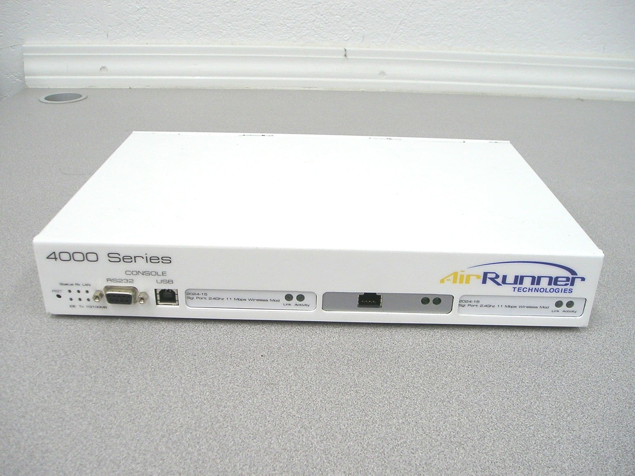
SJW-4000-2024-15
Jun 19, 2005BASE STATION WIRELESS ACCESS POINT/ROUTER
Equipment Class
DTS - Digital Transmission System