SKR-TKUZ-001Window Shade Controller Transceiver
Techniku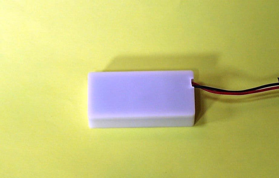
Click to zoom
Application Details
- Equipment Class
- DXT - Part 15 Low Power Transceiver, Rx Verified
- Date of Grant
- Jan 11, 2005
- Application Purpose
- Original Equipment
- Date of Application
- Jan 11, 2005
- Equipment Note
- Window Shade Controller Transceiver
- Frequency Range
- 908.42000000 - 908.42000000
- Company
- Techniku
- Country
- United States
Documents & Files

Document Text
Text extracted from the exhibit documents filed with the FCC. Open a document above to read the original.
Users Manual
Part Number: 795xxxx-MM Revision Date: 11.01.04 RF M ODULE – I NSTALLATION AND U SER M ANUAL Page 6 TKUZ-001 and TKUZ-002 325 Interlocken Parkway - Suite B200 - Broomfield, CO 80021 Toll Free: 800.416.7552 - Fax: 303.355.1471 - Website: www.techniku.com Part Number: 795xxxx-MM Revision Date: 11.01.04 Page RF M ODULE – I NSTALLATION AND U SER M ANUAL TKUZ-001 and TKUZ-002 © Techniku 2004. Innovation in Automation is a trademarks of Techniku. Licensed under the following U.S. patents: 5,081,402; 5,134,347; 5,391,967; 5,495,153; 5,729,103; 5,698,958; 5,714,855; 5,907,227; 5,883,480; 5,444,339; 6,060,852; 6,433,498; 6,116,320. Other U.S. and foreign patents pending. Congratulations on the purchase of your Techniku automation system with RF (radio frequency) control. After reviewing this instruction guide, simply update or install your automation system to operate with RF (radio frequency) control. Installation and usage is simple when following the steps in this manual. Before beginning, read this manual in its entirety prior to installing and operating the blind. With proper installation and care, your automated system with RF communication will provide years of beauty and convenience. Part Number: 795xxxx-MM Revision Date: 11.01.04 RF M ODULE – I NSTALLATION AND U SER M ANUAL Page 2 TKUZ-001 and TKUZ-002 T ABLE OF C ONTENTS Install RF Module ............................................................................... 3 Install RF Module to Group ...........................................................3-4 User Instructions ................................................................................. 4 Mounting Options ............................................................................. 4 Frequently Asked Questions ............................................................ 5 Troubleshooting................................................................................. 5 ! WARNING: Modifications or changes made by the user without written approval by Techniku will void the warranty and the user’s authority to operate the equipment. Part Number: 795xxxx-MM Revision Date: 11.01.04 Page 5 RF M ODULE – I NSTALLATION AND U SER M ANUAL TKUZ-001 and TKUZ-002 F REQUENTLY A SKED Q UESTIONS : 1. 2. T ROUBLESHOOTING : 1. 2. 3. Part Number: 795xxxx-MM Revision Date: 11.01.04 RF M ODULE – I NSTALLATION AND U SER M ANUAL Page 4 TKUZ-001 and TKUZ-002 I NSTALL RF M ODULE TO G ROUP (C ONT ’ D ): Step 7: Verify with Z-Wave controller (i.e.: RF remote control) that unit was successfully added to the group. ! CONGRATULATIONS! You have successfully installed RF control to your automated product! U SER I NSTRUCTIONS : In addition to using a variety of Z-Wave controllers, operate the automated product by pressing the button on the RF module. The automated product will toggle between open, stop and close. M OUNTING O PTIONS : There are a variety of mounting options to locate the RF module in automated window covering applications including... In the headrail or roller tube; Behind the automated window covering; Anywhere within 3” from the Techniku motor or Intelligence Interface. Part Number: 795xxxx-MM Revision Date: 11.01.04 Page 3 RF M ODULE – I NSTALLATION AND U SER M ANUAL TKUZ-001 and TKUZ-002 I NSTALL RF M ODULE : Step 1: Disconnect power (battery holder or power supply) from the Techniku motor, Intelligence Interface (I 2 ) or standard receiver. IMPORTANT: On products that require limits to be programmed, set the desired top and bottom limits with IR (infrared) prior to installation. Refer to specific product User Manual for details. ! Step 2: Verify automated product (window covering or motor) is installed in final location (i.e.: mounted in window, etc...). ! IMPORTANT: If automated product is using an IR receiver eye (on motor, I 2 or receiver), carefully remove the IR receiver from the Communication (COMM) port. Step 3: Plug RF Module into Communication (COMM) port on Techniku motor or I 2 . Step 4: Re-connect power (battery holder or power supply) to the Techniku motor or Intelligence Interface (I 2 ). Power must be 6v, 12v or 24v. I NSTALL RF M ODULE TO G ROUP : Step 5: Add RF unit to desired group with Z-Wave controller (preferably RF remote control). Step 6: Momentarily press the button on the RF module to add unit (automated product) to the group. RF Module Button
Cover Letter(s)
AHD EMC Lab, 92723 M152, Dowagiac, MI 49047, (269) 424-7014 505548.DOC Request for CONFIDENTIALITY: Page 1 of 1 NVLAP ACCREDITED NARTE Certified Engineer Professional Engineer Federal Communications Commission Equipment Approval Services, P.O. Box 358315 Pittsburgh, PA 15251-5315 ELITE Electronic Engineering TCB Services 1516 Centre Circle Downers Grove, IL 60515-1082 Re: Request for exhibits to be kept confidential. FCC ID: SKR-TKUZ-001 Gentlemen: Pursuant to 47CRF 0.459, Techniku Inc., and Twisthink LLC requests that these listed exhibits be held confidential. Circuit Block Diagram file names: EXB_Blockdiagram.pdf Theory/Description of Operation, file name: EXB_operation.doc Schematic file names: EXB_schematic.pdf Techniku and Twisthink have invested considerable resources into developing this product. Having sections of Exhibit B, listed above, available to ‘competition’ would negate the advantage achieved in developing this product. Since this product type is a major product line for Techniku, not protecting the details of the design would result in a financial hardship for the company. The Federal Communications Commission will be notified, in writing, of any changes in the software/programming of the device that could affect the device’s RF characteristics. Your prompt consideration of this application for product certification will be greatly appreciated. Should you have any questions regarding the content of this report, kindly contact me. Sincerely, Ted Chaffee, Technical Lab Manager Narte Certified Engineer, #EMC-002025-NE tel/fax: 269. 424.7014 email: [email protected]
ID Label/Location Info
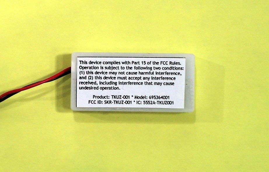
This device complies with Part 15 of the FCC Rules. Operation is subject to the following two conditions: (1) this device may not cause harmful interference, and (2) this device must accept any interference received, including interference that may cause undesired operation. Product: TKUZ-001 * Model: 695364001 FCC ID: SKR-TKUZ-001 * IC: 5552A-TKUZ001 Radio Frequency (RF) Module featuring:
RF Exposure Info
Test report #0400721F FCC 15.249 for 695364001 FCC ID: SKR-TKUZ-001 Tested October 1, 2004 AHD EMC Lab, 92723 M152, Dowagiac, MI 49047, (269) 424-7014 505546.DOC Misc. EXHIBIT: Page 1 of 1 MISC. EXHIBIT: RF EXPOSURE INFORMATION [2.1093(C)] The manufacturer and applicant: TECHNIKU, INC. 325 Interlocken Pkwy, Suite B. Broomfield, CO 80021 Product: Household curtain controller transceiver. Model: 695364001 Applicable Rules: 47CFR Part 15.249 Pursuant to 47CFR Part 1.1307(b), 47CFR Part 2.1091(c), and 47CFR Part 2.1093(c) this transmitting device, compliant to 47CFR Part 15.249, is categorically excluded from evaluation regarding the Maximum Permissible Exposure of RF energy.
Test Report
Test report #0400721F FCC 15.249 for 695364001 FCC ID: SKR-TKUZ-001 Tested October 1, 2004 AHD EMC Lab, 92723 M152, Dowagiac, MI 49047, (269) 424-7014 505568.DOC EXHIBIT E: Page 1 of 23 EXHIBIT E: REPORT OF MEASUREMENTS [2.1033(B6)] Test Report for FCC ID: SKR-TKUZ-001 FCC Part 2.1031, Part 15 Subpart C(15.249) Report #0400721F Issued 12/30/04 908.42MHZ TRANSCEIVER MODEL 695364001 Prepared for: TECHNIKU, Inc. 325 Interlocken Pkwy, Suite B Broomfield, CO 80021 Test Date(s): September 15, October 1, 2004 data recorded by Ted Chaffee, NCE This report prepared by: Ted Chaffee, NCE Technical Manager/Test Engineer, AHD Test report #0400721F FCC 15.249 for 695364001 FCC ID: SKR-TKUZ-001 Tested October 1, 2004 AHD EMC Lab, 92723 M152, Dowagiac, MI 49047, (269) 424-7014 505568.DOC EXHIBIT E: Page 2 of 23 TABLE OF CONTENTS EXHIBIT E: Report of Measurements [2.1033(b6)] .....................................................................................1 TABLE OF CONTENTS.........................................................................................................................2 Statements Concerning this Report.......................................................................................................3 Manufacturer/Applicant [2.1033(b1)] ....................................................................................................4 Measurement/Test Site Facility & Equipment........................................................................................4 Test Site [2.948, 2.1033(b6)] ......................................................................................................4 Measurement Equipment Used [2.947(d), 15.31(b)] ....................................................................4 Tested Configuration /Setup: [2.1033(b8)] ............................................................................................6 Support Equipment & Cabling .......................................................................................................6 Setup Diagram ...............................................................................................................................7 Summary of Results: .............................................................................................................................8 Changes made to achieve compliance..........................................................................................8 Standards Applied to Test: [2.1033(b6)]................................................................................................9 Test Methodology: [2.1033(b6)].............................................................................................................9 FORMULAS AND SAMPLE CALCULATIONS: ...........................................................................11 Test Data [2.1033(b6)].........................................................................................................................12 Relative Emission Level vs. Supply Voltage [15.31(e)] ...............................................................12 Modulation Characteristics ..........................................................................................................13 Occupied Bandwidth ....................................................................................................................13 Radiated Field Strength Measurements: [15.209, 15.249(a,d)] .................................................14 Out of Band Emissions [15.249(d)]..............................................................................................16 Line Conducted Measurements: [15.207(a)]...............................................................................18 Test report #0400721F FCC 15.249 for 695364001 FCC ID: SKR-TKUZ-001 Tested October 1, 2004 AHD EMC Lab, 92723 M152, Dowagiac, MI 49047, (269) 424-7014 505568.DOC EXHIBIT E: Page 3 of 23 Statements Concerning this Report NVLAP Accreditation: NVLAP Lab Code 200129-0 The scope of AHD accreditation is the conducted emissions, radiated emissions test methods of: IEC/CISPR 22: Limits and methods measurement of radio disturbance characteristics of information technology equipment. FCC Method – 47 CFT Part 15 – Digital Devices. AS/NZS 3548: Electromagnetic Interference – Limits and Methods of Measurement of Information Technology Equipment. IEC61000-4-2 and Amend.1: ElectroStatic Discharge Immunity Test Data: This test report contains data covered by the NVLAP accreditation. Subcontracted Testing: This report contains data recorded at the University of Michigan Radiation Laboratory. The University of Michigan test facility is located at 8501 Beck Road, Belleville, Michigan 48111. This test facility has been fully described and accepted by the FCC and Industry Canada. This facility was utilized to measure emissions occurring at frequencies greater than 6GHz. Test Traceability: The calibration of all measuring and test equipment and the measured data using this equipment are traceable to the National Institute for Standards and Technology (NIST). Limitations on results: The test results contained in this report relate only to the Item(s) tested. Any electrical or mechanical modification made to the test item subsequent to the test date shall invalidate the data presented in this report. Any electrical or mechanical modification made to the test item subsequent to this test date shall require an evaluation to verify continued compliance. Limitations on copying: This report shall not be reproduced, except in full, without the written approval of AHD. Limitations of the report: This report shall not be used to claim product endorsement by NVLAP, FCC, or any agency of the US Government. Statement of Test Results Uncertainty: Following the guidelines of NAMAS publication NIS81 and NIST Technical Note 1297, the Measurement Uncertainty at a 95% confidence level is determined to be: ± 1.4 dB Test report #0400721F FCC 15.249 for 695364001 FC…
Text truncated - open the document above for the full version.
Contact Information
Applicant
Dan A Huber(Engr Mgr)
Technical Contact
Twisthink, LLCBrent Bouws
[email protected]616-355-0469
130 Central Ave. · Holland, Michigan · United States
Non-Technical Contact
AHDTed Chaffee
[email protected]269-424-7014
Test Firm
AHD (Amber Helm Development, L.C.)Gordon Helm
Technical Specifications
| # | Rule Parts | Frequency Range | Power Output |
|---|---|---|---|
| 1 | 15C | 908.42 MHz - 908.42 MHz | - |