SLS-PSA1900Personal Smart Antenna
Broadlink Research, Inc.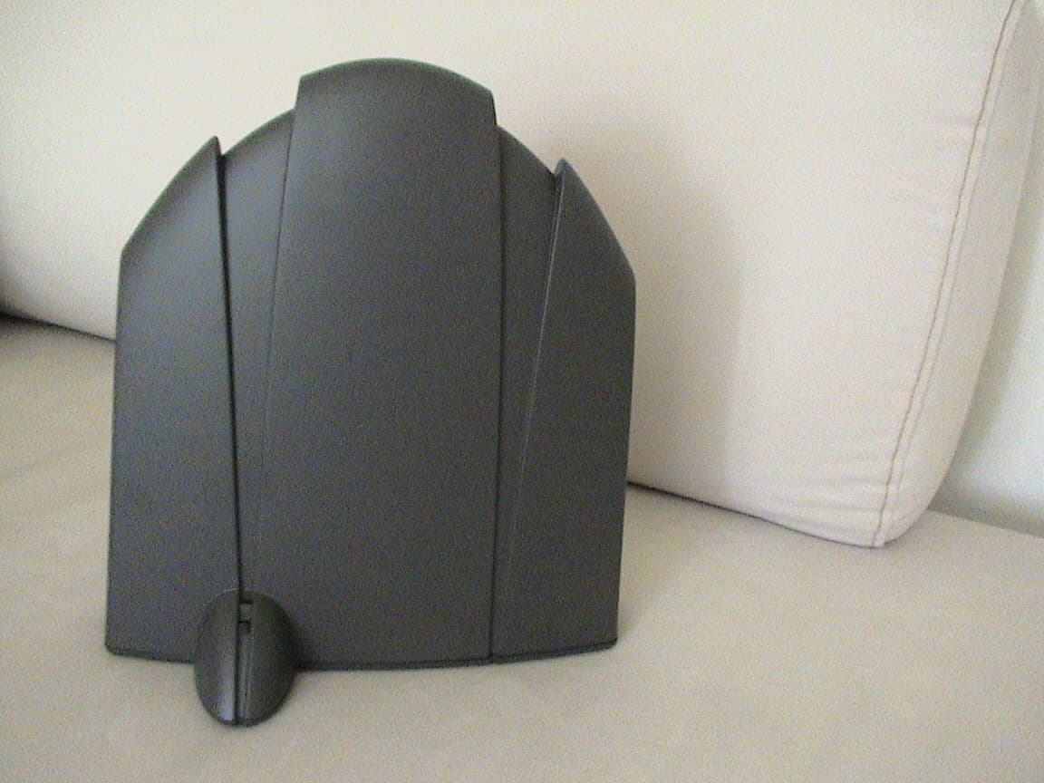
Click to zoom
Application Details
- Equipment Class
- PCB - PCS Licensed Transmitter
- Date of Grant
- Oct 13, 2004
- Application Purpose
- Original Equipment
- Date of Application
- Oct 13, 2004
- Equipment Note
- Personal Smart Antenna
- Frequency Range
- 1930.00000000 - 1990.00000000
- Company
- Broadlink Research, Inc.
- Country
- United States
Documents & Files
Document Text
Text extracted from the exhibit documents filed with the FCC. Open a document above to read the original.
Users Manual
Page 1 Broadlink Research 9000 Crow Canyon Road Suite S-200 Danville, CA 94506 (408)391-9019 (650)917-1038 Fax Broadlink Research, Inc. Personal Smart Antenna PSA-1900 Personal Smart Antenna Installation Guide Changes or modifications not expressly approved by the party responsible for compliance could void the user's authority to operate the equipment. This Class [B] digital apparatus complies with Canadian ICES-003. Cet appareil numérique de la classe [B] est conforme à la norme NMB-003 du Canada. Overview The Personal Smart Antenna (PSA) is a totally wireless device that will automatically adjust to the environment it is being installed. The device will provide the following feedback to help with an optimal installation. Installation Remove the PSA from the box, connect the power supply to the PSA, and then plug in the power supply to a power outlet. The PSA will display both the red and green light for about 5 seconds as the device learns the environment. NOTE: This equipment has been tested and found to comply with the limits for a Class B digital device , pursuant to Part 15 of the FCC Rules. These limits are designed to provide reasonable protection against harmful interference in a residential installation. This equipment generates, uses, and can radiate radio frequency energy and, if not installed and used in accordance with the instructions, may cause harmful interference to radio communications. However, there is no guarantee that interference will not occur in a particular installation. If this equipment does cause harmful interference to radio or television reception, which can be determined by turning the equipment off and on, the user is encouraged to try and correct the interference by one or more of the following measures: — Reorient or locate the receiving antenna. — Increase the separation between the equipment and receiver. — Connect the equipment into an outlet on a circuit different from that to which the receiver is connected. — Consult the dealer or an experienced radio/TV technician for help. Page 2 Broadlink Research 9000 Crow Canyon Road Suite S-200 Danville, CA 94506 (408)391-9019 (650)917-1038 Fax Optimal Location Please place the PSA on a desk top, table top, or shelf. The LED lights should be facing toward you and where you normally use your mobile phone (your desk chair). If the red LED light is displayed after power up (beyond the 5 second startup period), unplug the power supply to reset the PSA, and move the PSA to a new location. The red LED is indicating a poor location for the PSA. Plug in the PSA and try the new location. Continue until the green light on the PSA remains on. WARNING: While this device is in operation, a separation distance of at least 20 centimeters (8 inches) must be maintained between the radiating antenna and any person exposed to the transmitter in order to meet the FCC RF exposure guidelines. No change to the antenna or device is permitted. Doing so may result in the installed system exceeding RF exposure requirements. This device must not be co-located or operating in conjunction with any other antenna or radio transmitter. Installers and end users must follow the installation instructions provided in this guide. The side of the PSA facing the mobile phone If Green LED remains on, the PSA is installed in a good location in your room. Green LED Red LED If Red LED remains on, unplug the PSA and move it to a new location in your room. Page 3 Broadlink Research 9000 Crow Canyon Road Suite S-200 Danville, CA 94506 (408)391-9019 (650)917-1038 Fax Electrical Specifications: Operating frequency: Up link (Mobile to Base) 1850-1910 MHz Down link (Base to Mobile) 1930-1990 MHz Nominal passband gain : 26.6 dB. Maximum 45dB, software programmable Nominal bandwidth: 60 MHz for uplink and 60 MHz for downlink Rated mean output power: 22.7 dBm Input and output impedances: 50 ohms Notice: The Manufacturer's rated output power of this equipment is for single carrier operation. For situations when multiple carrier signals are present, the rating would have to be reduced by 3.5 dB, especially where the output signal is re-radiated and can cause interference to adjacent band users. This power reduction is to be by means of input power or gain reduction and not by an attenuator at the output of the device.
Cover Letter(s)
File: R56867 August 23, 2004 American TCB 6731 Whittier Avenue, Suite C110 McLean, VA. 22101 Gentlemen: The enclosed documents constitute a formal submittal and request for a Certification pursuant to Part 24E of FCC Rules (CFR 47) regarding the Personal Communication Service devices. Certification is being requested for Broadlink Research model Personal Smart Antenna - PSA 1900. The Personal Smart Antenna - PSA 1900has been tested and found to comply with FCC Part 24E limits for intentional radiators Elliott Laboratories, as duly authorized agent prepared this submittal. A copy of the letter of our appointment as agent is enclosed. If there are any questions or if further information is needed, please contact Elliott Laboratories for assistance. Sincerely, Juan Martinez Senior EMC Engineer JMM/jls Enclosure: R56867
Cover Letter(s)
American Telecommunications Certification Body Inc. 6731 Whittier Ave, McLean, VA 22101 September 14, 2004 RE: FCC ID: SGK-PSA1900_ATCB001692 Attention: Juan Martinez I have a few comments on this Application. Please note that further comments may arise in response to answers provided to the questions below. 1. Neither the manual nor the operational description give an indication as to where this device is to be used. Is this used in a car, or at home or other. Please explain. 2. Please note that as this is an amplifier and since the downlink has the capability of amplifying more than one channel, please provide intermodulation test data. Dennis Ward mailto:[email protected] The items indicated above must be submitted before processing can continue on the above referenced application. Failure to provide the requested information may result in application termination. Correspondence should be considered part of the permanent submission and may be viewed from the Internet after a Grant of Equipment Authorization is issued. Please do not respond to this correspondence using the email reply button. In order for your response to be processed expeditiously, you must submit your documents through the AmericanTCB.com website. Also, please note that partial responses increase processing time and should not be submitted. Any questions about the content of this correspondence should be directed to the sender.
Cover Letter(s)
Page 1 of 1 RE: FCC ID: SGK-PSA1900_ATCB001692 1. Neither the manual nor the operational description gives an indication as to where this device is to be used. Is this used in a car, or at home or other. Please explain. Response: The device is not for use in cars. It is for fixed applications at home or office. We can add a sentence to our manual to clarify this. 2. Please note that as this is an amplifier and since the downlink has the capability of amplifying more than one channel, please provide intermodulation test data. Response: Data has been uploaded for this request. Regards, Juan Martinez Sr. EMC Engineer
Cover Letter(s)
1 dward ATCB From: Juan Martinez [[email protected]] Sent: Tuesday, November 16, 2004 9:51 AM To: [email protected]; Jennifer Sanchez Cc: Susan - ATCB; William Graff Subject: Re: FW: Equipment Class Importance: High Hi Dennis, There have been other applications that have been label AMP for PCS repeaters. Since the unit, that was tested, is only to amplify weak signals and not to demodulate and re- transmit signals we assumed the correct equipment code was AMP. We also looked into previous approved applications, for PCS repeaters, that were also approved as AMP (FCC ID: BCR-RPT-MOR701). Let me know if this satisfies FCC inquiry. Thanks, Juan Martinez At 06:50 AM 11/16/2004 -0800, dward ATCB wrote: >Hi Jennifer / Juan >The FCC has the following question about this app. >The want justification for the equipment code AMP and why you did not >file under PCB. >This was originaly filed under an incorrect grantee code SGK Thanks > > >Dennis Ward >ATCB >Phone - Headquarters (703) 847-4700 >Phone - Dt Associates (209) 966-2145 >Phone -Alternate business (703) 880-4841 -----Original Message----- >From: OET Generic account [mailto:[email protected]] >Sent: Tuesday, November 16, 2004 4:28 AM >To: [email protected] >Subject: Equipment Class > >To: William Graff >From: Mike Nicolay > [email protected] > FCC Equipment Authorization Branch > >Re: FCC ID: SLS-PSA1900 > >Applicant: Broadlink Research, Inc. >Correspondence Reference Number: 15256 >731 Confirmation Number: TC677661 >Date of Original Email: 11/16/2004 > >Subject: Equipment Class > >The feeling here is that this application should be an equipment class >of PCB, not AMP. Please explain why you believe this to be AMP. > > > >The items indicated above must be submitted before processing can >continue on the above referenced application. Failure to provide the >requested information within 30 days of the original e-mail date may >result in application dismissal pursuant to Section 2.917(c). > 2 >DO NOT Reply to this email by using the Reply button. In order for >your response to be processed expeditiously, you must upload your >response via the Internet at www.fcc.gov, E-Filing, OET TCB Electronic Filing, TCB Login. >If the response is submitted through Add Attachments, a message which >informs the processing staff that a new exhibit has been submitted must >also be submitted via Submit Correspondence. Also, please note that >partial responses increase processing time and should not be submitted. > >Any questions about the content of this correspondence should be >directed to the e-mail address listed below the name of the sender. > Sr. EMC Engineer Elliott Laboratories
ID Label/Location Info
Page 1 Broadlink Research 9000 Crow Canyon Road Suite S-200 Danville, CA 94506 (408)391-9019 (650)917-1038 Fax Broadlink Research, Inc. FCC Label: Dimensions: 2 inch by 1 inch FCC ID: SLS-PSA1900 IC: 5309A-PSA1900 Personal Smart Antenna. Broadlink Research, Inc.Made in USA This device complies with Part 15 of the FCC Rules. Operation is subject to the following two conditions: (1) This device may not cause harmful interference, and (2) this device must accept any interference received, including interference that may cause undesired operation
RF Exposure Info
MPE Exposure Formula: S = ( P X G ) / ( 4 X p X d^2 ) where: S = power density P = transmitter conducted power in (mW) G = antenna numeric gain d = distance to radiation center (m) or (.02^2 ) = .020 m Gain =6Numeric8dBi Power = 182mW22.6dBm Frequency =1850MHz1.000mW/cm^2 Cable Loss =0dB EIRP =1148.15mW1148.15mW R (cm) = S (20cm) = Gain =10Numeric10dBi Power = 141mW21.5dBm Frequency =1880MHz1.000mW/cm^2 Cable Loss =0dB EIRP =1412.54mW1412.54mW R (cm) = S (20cm) = Gain =10Numeric10dBi Power = 107mW20.3dBm Frequency =1910MHz1.000mW/cm^2 Cable Loss =0dB EIRP =1071.52mW1071.52mW R (cm) = S (20cm) = Enter Data in Linear Units Enter Data in Linear Units 0.228 0.281 9.5586172 10.6021774 Enter Data in Linear Units 9.23411050.213 Gain =5Numeric7dBi Power = 62mW17.9dBm Frequency =1930MHz1.000mW/cm^2 Cable Loss =0dB EIRP =309.03mW309.03mW R (cm) = S (20cm) = Gain =5Numeric7dBi Power = 141mW21.5dBm Frequency =1950MHz1.000mW/cm^2 Cable Loss =0dB EIRP =707.95mW707.95mW R (cm) = S (20cm) = Gain =5Numeric7dBi Power = 186mW22.7dBm Frequency =1990MHz1.000mW/cm^2 Cable Loss =0dB EIRP =933.25mW933.25mW R (cm) = S (20cm) = 8.61777340.186 Enter Data in Linear Units 4.95901100.061 Enter Data in Linear Units 7.50576680.141 Enter Data in Linear Units
Test Report
File: R56867 Page 1 of 18 Electromagnetic Emissions Test Report In Accordance With Industry Canada Radio Standards Specification 131 issue 2, FCC Part 24 Subpart E on the Broadlink Research Model: Personal Smart Antenna - PSA 1900 FCC ID: SLS-PSA1900 UPN: 5309A-PSA1900 GRANTEE: Broadlink Research 4779 Josefa Lane Los Altos, CA 94022 TEST SITE: Elliott Laboratories, Inc. 684 W. Maude Avenue Sunnyvale, CA 94086 REPORT DATE: August 23, 2004 FINAL TEST DATE: July 27 and August 17, 2004 AUTHORIZED SIGNATORY: ______________________________ Juan Martinez Senior EMC Engineer Elliott Laboratories, Inc. is accredited by the A2LA, certificate number 2016-01, to perform the test(s) listed in this report. This report shall not be reproduced, except in its entirety, without the written approval of Elliott Laboratories, Inc. Elliott Laboratories, Inc. -- EMC Department Test Report Report Date: August 23, 2004 File: R56867 Page 2 of 18 Pages TABLE OF CONTENTS COVER PAGE.............................................................................................................................................................1 TABLE OF CONTENTS ..........................................................................................................................................2 FCC CERTIFICATION INFORMATION.............................................................................................................3 DECLARATIONS OF COMPLIANCE..................................................................................................................5 SCOPE........................................................................................................................................................................6 OBJECTIVE ..............................................................................................................................................................6 SUMMARY OF TEST RESULTS ...........................................................................................................................7 PART 24E AND RSS-131 TEST SUMMARY..........................................................................................................7 MEASUREMENT UNCERTAINTIES ...................................................................................................................8 EQUIPMENT UNDER TEST (EUT) DETAILS ....................................................................................................9 GENERAL..............................................................................................................................................................9 OTHER EUT DETAILS.........................................................................................................................................9 ENCLOSURE.........................................................................................................................................................9 MODIFICATIONS.................................................................................................................................................9 SUPPORT EQUIPMENT.......................................................................................................................................9 EUT INTERFACE PORTS ..................................................................................................................................10 EUT OPERATION DURING TESTING.............................................................................................................10 TEST SITE...............................................................................................................................................................11 GENERAL INFORMATION...............................................................................................................................11 CONDUCTED EMISSIONS CONSIDERATIONS ............................................................................................11 RADIATED EMISSIONS CONSIDERATIONS ................................................................................................11 MEASUREMENT INSTRUMENTATION ..........................................................................................................12 RECEIVER SYSTEM ..........................................................................................................................................12 INSTRUMENT CONTROL COMPUTER ..........................................................................................................12 PEAK POWER METER ......................................................................................................................................12 FILTERS/ATTENUATORS ................................................................................................................................12 ANTENNAS.........................................................................................................................................................13 ANTENNA MAST AND EQUIPMENT TURNTABLE.....................................................................................13 INSTRUMENT CALIBRATION.........................................................................................................................13 TEST PROCEDURES ............................................................................................................................................14 SPECIFICATION LIMITS AND SAMPLE CALCULATIONS........................................................................18 RADIATED EMISSIONS SPECIFICATION LIMITS .......................................................................................18 CALCULATIONS – EFFECTIVE RADIATED POWER ..................................................................................18 EXHIBIT 1: Test Equipment Calibration Data................................................................................................…
Text truncated - open the document above for the full version.
Test Report
EMC Test Data Client: Model: T-Log Number: Account Manager: Emissions Spec: Immunity Spec: Contact: EMC Test Data - B / Radio -Environment: Class: For The Broadlink Broadlink PSA 1900 Hamid Najafi J55671 T55817 Sue Pelzl Job Number: FCC Part 15 / 24 E & RSS-131 Date of Last Test: 10/7/2004 Model PSA 1900 T-Log: T55817.xls, Rev 1.0CoverPage 1 of 18 EMC Test Data Client: Contact: Spec: Test Specifics General Test Configuration Ambient Conditions: 18 °C 40% Summary of Results Result Pass Pass BroadlinkJob Number: J55671 Model: PSA 1900 T-Log Number: T55817 Account Manager: Sue Pelzl Hamid Najafi FCC Part 15 / 24 E & RSS-131Class:N/A Radio Performance Test - FCC 24E & RSS-131 RF Port Measurements Objective: The objective of this test session is to perform final qualification testing of the EUT with respect to the specification listed above. Date of Test: 10/7/2004 Config. Used: 1 Test Engineer: Juan Martinez Config Change: None Test Location: SVOATS #2 EUT Voltage: 120V/60Hz The EUT's rf port was connected to the measurement instrument's rf port, via an attenuator or dc-block if necessary. Temperature: Rel. Humidity: Run #Test PerformedLimitValue / Margin 1Two Tone - IntermodulationFCC 24E & RSS-131Refer to individual plots 1 Conducted spurious emissions, 30MHz - 20,000 MHz, transmit mode FCC 24E & RSS-133Refer to individual plots Deviations From The Standard No deviations were made from the requirements of the standard. Modifications Made During Testing: No modifications were made to the EUT during testing T55817.xlsPart 24 Intermod CE 07-Oct-04Page 2 of 18 EMC Test Data Client: Contact: Spec: BroadlinkJob Number: J55671 Model: PSA 1900 T-Log Number: T55817 Account Manager: Sue Pelzl Hamid Najafi FCC Part 15 / 24 E & RSS-131Class:N/A Run #1: Two Tone - Intermodulation (1930 - 1990 Downlink) GSM Intermodulation T55817.xlsPart 24 Intermod CE 07-Oct-04Page 3 of 18 EMC Test Data Client: Contact: Spec: BroadlinkJob Number: J55671 Model: PSA 1900 T-Log Number: T55817 Account Manager: Sue Pelzl Hamid Najafi FCC Part 15 / 24 E & RSS-131Class:N/A GSM Out of band T55817.xlsPart 24 Intermod CE 07-Oct-04Page 4 of 18 EMC Test Data Client: Contact: Spec: BroadlinkJob Number: J55671 Model: PSA 1900 T-Log Number: T55817 Account Manager: Sue Pelzl Hamid Najafi FCC Part 15 / 24 E & RSS-131Class:N/A TDMA Intermodulation T55817.xlsPart 24 Intermod CE 07-Oct-04Page 5 of 18 EMC Test Data Client: Contact: Spec: BroadlinkJob Number: J55671 Model: PSA 1900 T-Log Number: T55817 Account Manager: Sue Pelzl Hamid Najafi FCC Part 15 / 24 E & RSS-131Class:N/A TDMA Out of band T55817.xlsPart 24 Intermod CE 07-Oct-04Page 6 of 18 EMC Test Data Client: Contact: Spec: BroadlinkJob Number: J55671 Model: PSA 1900 T-Log Number: T55817 Account Manager: Sue Pelzl Hamid Najafi FCC Part 15 / 24 E & RSS-131Class:N/A EDGE Intermodulation T55817.xlsPart 24 Intermod CE 07-Oct-04Page 7 of 18 EMC Test Data Client: Contact: Spec: BroadlinkJob Number: J55671 Model: PSA 1900 T-Log Number: T55817 Account Manager: Sue Pelzl Hamid Najafi FCC Part 15 / 24 E & RSS-131Class:N/A EDGE Out of band T55817.xlsPart 24 Intermod CE 07-Oct-04Page 8 of 18 EMC Test Data Client: Contact: Spec: BroadlinkJob Number: J55671 Model: PSA 1900 T-Log Number: T55817 Account Manager: Sue Pelzl Hamid Najafi FCC Part 15 / 24 E & RSS-131Class:N/A CDMA Intermodulation T55817.xlsPart 24 Intermod CE 07-Oct-04Page 9 of 18 EMC Test Data Client: Contact: Spec: BroadlinkJob Number: J55671 Model: PSA 1900 T-Log Number: T55817 Account Manager: Sue Pelzl Hamid Najafi FCC Part 15 / 24 E & RSS-131Class:N/A CDMA Out of band T55817.xlsPart 24 Intermod CE 07-Oct-04Page 10 of 18 EMC Test Data Client: Contact: Spec: BroadlinkJob Number: J55671 Model: PSA 1900 T-Log Number: T55817 Account Manager: Sue Pelzl Hamid Najafi FCC Part 15 / 24 E & RSS-131Class:N/A CDMA Intermodulation T55817.xlsPart 24 Intermod CE 07-Oct-04Page 11 of 18 EMC Test Data Client: Contact: Spec: BroadlinkJob Number: J55671 Model: PSA 1900 T-Log Number: T55817 Account Manager: Sue Pelzl Hamid Najafi FCC Part 15 / 24 E & RSS-131Class:N/A CDMA out of band T55817.xlsPart 24 Intermod CE 07-Oct-04Page 12 of 18 EMC Test Data Client: Contact: Spec: BroadlinkJob Number: J55671 Model: PSA 1900 T-Log Number: T55817 Account Manager: Sue Pelzl Hamid Najafi FCC Part 15 / 24 E & RSS-131Class:N/A GSM Intermodulation T55817.xlsPart 24 Intermod CE 07-Oct-04Page 13 of 18 EMC Test Data Client: Contact: Spec: BroadlinkJob Number: J55671 Model: PSA 1900 T-Log Number: T55817 Account Manager: Sue Pelzl Hamid Najafi FCC Part 15 / 24 E & RSS-131Class:N/A GSM Out of band T55817.xlsPart 24 Intermod CE 07-Oct-04Page 14 of 18 EMC Test Data Client: Contact: Spec: BroadlinkJob Number: J55671 Model: PSA 1900 T-Log Number: T55817 Account Manager: Sue Pelzl Hamid Najafi FCC Part 15 / 24 E & RSS-131Class:N/A EDGE Intermodulation T55817.xlsPart 24 Intermod CE 07-Oct-04Page 15 of 18 EMC Test Data Client: Contact: Spec: BroadlinkJob Number: J55671 Model: PSA 1900 T-Log Number: T55817 Account Manager: Sue Pelzl Hamid Najafi FCC Part 15 / 24 E & RSS-131Class:N/A EDGE out of band T55817.xlsPart 24 Intermod CE 07-Oct-04Page 16 of 18 EMC Test Data Client: Contact: Spec: BroadlinkJob Number: J55671 Model: PSA 1900 T-Log Number: T55817 Account Manager: Sue Pelzl Hamid Najafi FCC Part 15 / 24 E & RSS-131Class:N/A TDMA Intermodulation T55817.xlsPart 24 Intermod CE 07-Oct-04Page 17 of 18 EMC Test Data Client: Contact: Spec: BroadlinkJob Number: J55671 Model: PSA 1900 T-Log Number: T55817 Account Manager: Sue Pelzl Hamid Najafi FCC Part 15 / 24 E & RSS-131Class:N/A TDMA Out of Band T55817.xlsPart 24 Intermod CE 07-Oct-04Page 18 of 18
Contact Information
Applicant
Hamid Najafi(CEO)
Technical Contact
Elliott Laboratories, Inc.Juan Martinez
[email protected]408-245-7800
684 W. Maude Ave · Sunnyvale, California · United States
Technical Specifications
| # | Rule Parts | Frequency Range | Power Output | Emission | Tolerance |
|---|---|---|---|---|---|
| 8 | 24E | 1.93 GHz - 1.99 GHz | 186.00 mW | G7W | Amp |