SMIGPDSTransmitter
Accurate Technology, Inc.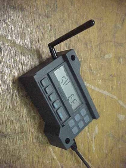
Click to zoom
Application Details
- Equipment Class
- DSC - Part 15 Security/Remote Control Transmitter
- Date of Grant
- Nov 11, 2004
- Application Purpose
- Original Equipment
- Date of Application
- Nov 11, 2004
- Equipment Note
- Transmitter
- Frequency Range
- 433.92000000 - 433.92000000
- Company
- Accurate Technology, Inc.
- Country
- United States
Documents & Files
Document Text
Text extracted from the exhibit documents filed with the FCC. Open a document above to read the original.
Users Manual
User’s Manual for: ProScale Model 150 & 250 Systems & All ProScale Products using the Firmware V2.0 and Higher ProScale ™ Model 150 Model 250 General Purpose LCD Digital Display ProScale M150, M250 and all products with General Purpose LCD Digital Displays 2 of 2 Warranty Accurate Technology, Inc., warrants the Model 150 and Model 250 ProScale against defective parts and workmanship for 3 years commencing from the date of original purchase. Upon notification of a defect, Accurate Technology, Inc., shall have the option to repair or replace any defective part. Such services shall be the customer's sole and exclusive remedy. Expenses incidental to repair, maintenance, or replacement under warranty, including those for labor and material, shall be borne by Accurate Technology, Inc. (Including freight or transportation charges during the first 30 days). Except as expressly provided in this warranty, Accurate Technology, Inc., does not make any warranties with respect to the product, either expressed or implied, including implied warranties of merchantability or fitness for a particular purpose, except as expressly provided in this agreement. Accurate Technology, Inc., shall not be liable for any special, incidental, or consequential damages or for loss, damage or expense directly or indirectly arising from the customer's use of or inability to use the equipment either separately or in combination with other equipment, or for personal injury or loss or destruction of other property, or from any other cause. To request repair work (either warranty qualified parts or not), contact Accurate Technology, Inc. directly by phone, fax, or e-mail. A R eturned M erchandise A uthorization (RMA) number is required before returning a product for repair. Accurate Technology, Inc. +1 828.654.7920 800.233.0580 828.654.8824 (F) www.proscale.com [email protected] P/N 800-1097-001, Revision D, Copyright © 2003, Accurate Technology, Inc. All rights reserved. S S A A F F E E T T Y Y W W A A R R N N I I N N G G Before installing ProScale on any machinery: Turn off the machine and disconnect the power . S S A A F F E E T T Y Y W W A A R R N N I I N N G G ProScale M150, M250 and all products with General Purpose LCD Digital Displays 3 of 3 FCC Statement This equipment has been tested and found to comply with the limits for a class B digital device, pursuant to part 15 of the FCC Rules. These limits are designed to provide reasonable protection against harmful interference in a residential installation. This equipment generates, uses and can radiate radio frequency energy and if not installed and used in accordance with the instructions, may cause harmful interference to radio communications. However, there is no guarantee that interference will not occur in a particular installation. If this equipment does cause harmful interference to radio or television reception, which can be determined by turning the equipment off and on, the user is encouraged to correct the interference by one or more of the following measures: • Reorient or relocate the receiving antenna. • Increase the separation between the equipment and the receiver. • Connect the equipment to an outlet on a circuit different from that to which the receiver is connected. • Consult the dealer or an experienced radio/television technician for help. Operation with non-approved equipment is likely to result in interference to radio and TV reception. The user is cautioned that changes and modifications made to the equipment without the approval of the manufacturer could void the user’s authority to operate this equipment. FCC ID: SMIGPDS This device complies with Part 15 of the FCC Rules. Operation is subject to the following two conditions: (1) This device may not cause harmful interference and (2) This device must accept any interference received including interference that may cause undesired o peration. ProScale M150, M250 and all products with General Purpose LCD Digital Displays 4 of 4 Table of Contents SECTION 1 GENERAL INFORMATION ...................................................................................6 Introduction.............................................................................................................................................6 What This Manual Includes ....................................................................................................................6 ProScale Terminology ............................................................................................................................8 Scales.....................................................................................................................................................9 Absolute ..............................................................................................................................................9 Incremental........................................................................................................................................10 Shortening Scales .............................................................................................................................10 Readheads ...........................................................................................................................................10 Readheads ...........................................................................................................................................11 Absolute ............................................................................................................................................11 Incremental........................................................................................................................................11 Digital Displays .....................................................................................................................................12 General Purpose Surface Mount .......................…
Text truncated - open the document above for the full version.
Users Manual
ProScale M150, M250 and all products with General Purpose LCD Digital Displays 11 of 11 Readheads Absolute Absolute (ABS) style readheads have “BLACK END OF SCALE” labels on the cover, and the wire exits from the corner of the housing. Care must be taken not to damage the brass “fingers” inside the readhead housing. ABS style readheads, used in all Model 150 and Model 250 systems, must only be used on ABS scales and with a particular orientation. Each readhead has an arrow on the label pointing in the direction of the “BLACK END OF SCALE”. Each ABS style scale will have one end painted black. This relationship is very important, since the readhead will work, but produce erratic results if installed backwards. To insure proper operation, be sure the arrow on the readhead is pointing toward the BLACK end of the scale. The standard ABS readhead has 3m (10 ft.) of cable. For special cable lengths, contact Accurate Technology, Inc. Standard ABS Readhead is supplied with a 3m (10ft) cable OLD Part # 701-1510-001, NEW Part # 701-1500-120 Incremental Incremental style readheads do not have labels on the cover, and the wire exits from the center of the housing. Care must be taken not to damage the brass “fingers” inside the readhead housing. Incremental readheads work on incremental scales ONLY. Orientation of incremental readheads on the scale is not important. Incremental readheads are still used on some current Accurate Technology products such as: ProStop, ProKit, Measuring Kits, ProCaliper, and ProPanel. Standard Incremental Readhead is supplied with a 300mm (12in) cable Old Part # 701-1002-002, NEW Part # 701-1500-N12 Avoid making extension cables. If a different cable length is required, contact Accurate Technology, Inc. Readheads used on Absolute and Incremental systems should never be mixed. ProScale M150, M250 and all products with General Purpose LCD Digital Displays 12 of 12 Digital Displays Accurate Technology makes several different digital displays for use with ProScale products. Each display has unique features that make it suitable for different applications. The following is a listing of the displays and their descriptions: General Purpose Surface Mount Basic (no auxiliary keys) 2AA Bat. 701-1600-120 NEW Part # Effective April 2004: 700-1600-220 Full Fuctionality, 2AA Battery 701-1600-100 NEW Part # Effective April 2004: 700-1600-200 Full Fuctionality, 24VDC 701-1605-100 NEW Part # Effective April 2004: 700-1600-205 General Purpose 1/4 DIN Panel Mount Full Fuctionality, 2D Battery 701-1570-100 NEW Part # Effective April 2004: 700-1600-400 Full Fuctionality, 24VDC 701-1560-500 NEW Part # Effective April 2004: 700-1600-300 Operation Instructions Included in this Manual Other Digital Displays 1/8 DIN Panel Mount 24VDC LED, 700-1600-090 RS485 Output 1/4 DIN Panel Mount 24VDC Backlit LCD 700-1600-110 Position Control Unit Dual Input Panel Mount 24VDC 2 line Backlit LCD 700-1600-500 2 inputs, A+B, A-B, RS232 out Operation Covered in Separate Manual ProScale M150, M250 and all products with General Purpose LCD Digital Displays 13 of 13 Product Specifications ProScale Model 150 & Model 250 Measuring Range*: Model 150: 2 Standard Sizes: 0-250mm (10in) and 0-450mm (18in) Model 250: 9 Standard Sizes: 0 to 300mm, 600mm, 1.3m, 2.4m, 3.0m, 3.6m, 6.0m (0 to 12in, 24in, 52in, 96in, 120in, 144in, 240in ) Accuracy : + (.025 + .064 x L / 430) mm; max error + 0.20mm @ 1.3 to 6m + (.001 + .0025 x L / 17) in; max error + .008in @ 4 to 20 feet (L = length of measurement in mm or inches) Resolution .1mm/.01cm/.01in; .01mm/.001cm/.001in; .01mm/.001cm/.0004in Repeatability : .01mm or .001cm or .001in Display Range: + 9999.99 mm; + 999.999 cm; + 999.999 in; + 399 63/64 in Operating Temp: 0 to 51 ° C; 32 to 120 ° F Temp Coef: 25ppm/°C; 13ppm/ ° F Max. Slew Rate: 400 mm/sec. (15 inches/sec.) Available Displays: General Purpose Surface Mount LCD (Digital Readouts) General Purpose 1/4 DIN Panel Mount LCD 1/8 DIN Panel Mount LED 1/4 DIN Panel Mount Position Control LCD Dual Input Panel Mount LCD Accessories: See Section 6 Output Format: Mitutoyo SPC, RS232, RS485 (Selected displays) Readhead: 3m (10’), six-conductor cable terminated by RJ12 connector. (Maximum cable length 6m) Dimensions: Available at www.proscale.com . US Patents : 4420754, 4879508, 4878013, 4959615 Warranty: Three years from date of purchase. All ProScale products are MADE IN USA * MEASUREMENT lengths are approximately 100mm (4in) shorter than PHYSICAL lengths. ProScale M150, M250 and all products with General Purpose LCD Digital Displays 14 of 14 S ECTION 2 P RO S CALE M ODEL 150 ProScale Model 150 A General Purpose measuring system with standard measuring ranges of 250mm (10”) or 450mm (18”). Model 150 systems use ABS style scales, ABS style readheads, and any of the available digital displays. Neither the scale nor readhead are compatible with any Accurate Technology incremental technology measuring systems. ProScale Model 150 is easy to install. By following the basics of good installation, reliable, error-free operation can be expected. ProScale M150 can be used in many different measurement applications, and with numerous types and brands of equipment. Therefore all installations will be a little different and it is the responsibility of the installer to choose the bolts, screws, or other mounting hardware that guarantee proper installation for optimum operation. Note : If a custom kit was ordered which contains instructions for installing ProScale on a specific product, follow those instructions rather than the general instructions here. ProScale Model 150-10 shown with Surface Mount General Purpose LCD Digital Display ProScale M150, M250 and all products with General Purpose LCD Digital Displays 15 of 15 Connector Link Guide Clip Installation 1. Note the orientation of the readhead on the scale. Be sure the arrow on the readhead points towards the “BLACK END OF SCALE” . This orientation is critical for proper operation of ProScale. B…
Text truncated - open the document above for the full version.
Users Manual
ProScale M150, M250 and all products with General Purpose LCD Digital Displays 16 of 16 5. The Digital Display may be mounted in a location which allows for easy viewing by the operator. The location of all parts should also safeguard the cable from possible damage. ProScale wiring should be kept away from electrical wiring and motors. Plug the readhead into the display. See Section 4: Digital Display Operation. Typical Model 150 Installations Moving Part Connector Link Readhead Guide Clip Scale Readhead Moving part Readhead stationary, Scale moves Scale stationary, Readhead moves ProScale M150, M250 and all products with General Purpose LCD Digital Displays 17 of 17 Calibration Once installed, ProScale can be calibrated easily and quickly. Following is an example for calibrating ProScale on an industrial wide belt sander. Other installations follow the same general procedure. 1. Check to be sure installation of all parts is complete, all fasteners are secure, and the readhead is plugged into the digital display. 2. Set-up the machine to operate as normal. Run a part through the sander. 3. Measure the thickness of the sanded part with the most precise measuring tool available (digital calipers if possible). 4. Press the zero key on the ProScale digital display then press and hold the PLUS key to scroll until the thickness measurement is displayed (The longer the PLUS key is held down, the faster the display will scroll). 5. When the proper reading is reached, lock the display if desired. This prevents accidentally re-zeroing of the display. See Section 4: Lock Mode . If the direction of movement (+ and -) on the digital display is opposite the desired direction, the display programming should be changed. See Section 4: Programming (Programming Parameter Pr0). Maintenance Although the ProScale will operate in a dry environment of non-conductive debris such as sawdust, the system should be cleaned of excess debris when necessary. This will prevent premature damage to the scale or readhead. Should the scale become difficult to move, check to see if debris has built up under the readhead and remove if necessary. Find and remove any burrs which may have developed on the aluminum scale. Do not use any liquid lubricants on the scale assembly, as this may impede the readhead's ability to operate properly and will attract other contaminants to the scale. The Digital Display should be cleaned periodically with compressed air to remove any dust on the lens and keys. All mounting fasteners should be checked occasionally for tightness . ProScale M150, M250 and all products with General Purpose LCD Digital Displays 18 of 18 S ECTION 3 P RO S CALE M ODEL 250 ProScale Model 250 A General Purpose measuring system with nine standard measuring ranges from 0-300mm (12in.) up to 0-6m (20ft.). Model 250 systems use ABS style scales, ABS style readheads, and any of the available digital displays. Neither the scale nor readhead are compatible with any Accurate Technology incremental technology measuring systems. ProScale Model 250 is easy to install. By following the basics of good installation, reliable, error-free operation is assured. ProScale M250 can be used in many different measurement applications, and with numerous types and brands of equipment. Therefore all installations will be a little different and it is the responsibility of the installer to choose the bolts, screws, or other mounting hardware that guarantee proper installation for optimum operation. Note: If a custom kit was ordered which contains instructions for installing ProScale on a specific product, follow those instructions rather than the general instructions here. ProScale Model 250 shown with Panel Mount General Purpose LCD Display ProScale M150, M250 and all products with General Purpose LCD Digital Displays 19 of 19 Guide Clip Installation 1. Note the orientation of the readhead on the scale. Be sure the arrow on the readhead points towards the “BLACK END OF SCALE” . This orientation is critical for proper operation of ProScale. Be sure the mounting location for the readhead and scale will allow this orientation. Take care when sliding the readhead onto the scale so the brass “fingers” inside the readhead do not get damaged. (A slight “wiggling” motion when installing the readhead on the scale will simplify the process.) 2. Determine an appropriate mounting location for the system. Most applications of the Model 250 will have the scale held stationary while the readhead is moved along the scale. However, the ProScale will read correctly if the readhead is moved along the scale or if the scale is moved through the readhead. 3. When the scale is stationary and the readhead moves to measure, you should use the Guide Clip to move the readhead along the scale (see figures on next page). Mount the scale using M4 (or #8) screws. Be sure the screw heads do not protrude above the surface of the extrusion. Check that the scale is properly aligned as the readhead is moved over its length (the Guide Clip will compensate for slight misalignment). Adjust scale alignment if necessary. For accurate measurements, the guide clip must be mounted perpendicular to the direction of travel of the readhead. The guide clip should exert some pressure over the full range of travel on the readhead so the two move as a single unit. Note: Failure to use the guide clip could void the warranty . 4. The Digital Display may be mounted in a location which allows for easy viewing by the operator. The location of all parts should also safeguard the cable from possible damage. ProScale wiring should be kept away from electrical wiring and motors. Plug the readhead into the display. See Section 4: Digital Display Operation Note: If any other mounting method is used, observe the following: A. Do not drill through the green portion of the scale at any point over which the readhead will travel. B. Do not mount the scale so the mounting hardware interferes with the movement …
Text truncated - open the document above for the full version.
Users Manual
ProScale M150, M250 and all products with General Purpose LCD Digital Displays 21 of 21 Calibration Once installed, ProScale can be calibrated easily and quickly. Following is an example for calibrating ProScale on a table saw fence. Other installations follow the same general procedure. 1. Check to be sure installation of all parts is complete, all fasteners are secure, and the readhead is plugged into the digital display. 2. Cut a part using the normal fence operation. 3. Do Not move fence until calibration is completed. 4. Measure the dimension of the part with the most precise measuring tool available (i.e. digital calipers). 5. Press the zero key on the ProScale digital display then press and hold the PLUS key to scroll until the measurement you just made is displayed. (The longer the PLUS key is held down, the faster the display will scroll). 6. When the proper reading is reached, lock the display if desired. This prevents accidentally re-zeroing of the display. See Section 4: Lock Mode If the direction of movement (+ and -) on the digital display is opposite the desired direction, the display programming should be changed. See Section 4: Programming (Programming Parameter Pr0). Maintenance Although the ProScale will operate in a dry environment of non-conductive debris such as sawdust, the system should be cleaned of excess debris when necessary. This will prevent premature damage to the scale or readhead. Should the scale become difficult to move, check to see if debris has built up under the readhead and remove if necessary. Find and remove any burrs which may have developed on the aluminum scale. Do not use any liquid lubricants on the scale assembly, as this may impede the readhead's ability to operate properly and will attract other contaminants to the scale. The Digital Display should be cleaned periodically with compressed air to remove any dust on the lens and keys. All mounting fasteners should be checked occasionally for tightness . ProScale M150, M250 and all products with General Purpose LCD Digital Displays 22 of 22 S ECTION 4 D IGITAL D ISPLAY O PERATION This section covers the installation, programming and operation of the General Purpose LCD Digital Display (Firmware V2.0 and higher). This display is supplied on ProScale Model 150 and Model 250 systems (covered in this manual) as well as several other ProScale products whose operation is covered in their respective manuals but the digital display information is contained here. If your ProScale product has a digital display other than a General Purpose LCD Digital Display, please refer to the separate manual for that individual display. General Purpose LCD Digital Displays come in several configurations. The major differences are described below: Surface Mount Displays Basic Fully Programmable Fully Programmable 2AA Batteries 2AA Batteries 24VDC SPC output SPC output Limit/Mon. Signal Output LCD Backlighting P/N 701-1600-120 P/N 701-1600-100 P/N 701-1605-100 NEW P/N 700-1600-220 P/N 700-1600-200 P/N 700-1600-205 (New Part numbers effective April 1, 2004) Basic Display This display operates on 2AA batteries. It is ideal for machinery applications where more advanced programming features are not desired or required. Functions such as switching between ABSolute and INCremental readings, SENDing data, MONitoring drift, HOLDing a reading and Special Function keys are not available. This display does not have Signal output, Back-Lighting, or special function capability. Programming Parameters Pr0 - Pr8 and Pr16 & 17 are applicable to the BASIC display. ProScale M150, M250 and all products with General Purpose LCD Digital Displays 23 of 23 Fully Programmable, Battery Operation This display operates on 2AA batteries. It includes all the features of the BASIC display plus: It has an auxiliary keypad with 6 keys for: switching between ABSolute readings and INCremental measurements, MONitoring position drift, SENDing data out the SPC connector, HOLDing the reading, and F1 & F2 special function keys. This display does not have Limit Alarm / Monitor Output , or Back-Lighting. Programming Parameters from Pr0 to Pr23 except Pr14, 15 & 22 are applicable to this display. Fully Programmable, 24VDC This display includes all the features of the PROGRAMMABLE Battery display. This display is intended to operate on 24VDC. It comes with a connector that allows easy connections for supply voltage and also serves as the output connection for the position Limit / Monitoring output signal. Programming Parameters Pr0 to Pr23 are applicable to this display. Mounting the Surface Mount Display The SURFACE MOUNT General Purpose Digital Display may be mounted: • Using Velcro or Double sided tape • Drilling out any of the four holes from the inside of the case • Using any of the six holes on the back of the case which may tapped for M2 or 4-40 screws. NOTE : Care must be taken when using the inside holes. If using the lower left hole as shown above, be sure to use a screw that will not rise above the extruded countersink as this may short the input connector. ProScale M150, M250 and all products with General Purpose LCD Digital Displays 24 of 24 Panel Mount Displays The General Purpose LCD Display for panel and enclosure mounting applications comes in two versions. Both are designed to fit a ¼ DIN (90mm x 90mm) (3.5in x 3.5in) panel opening. One version is battery operated (2D) and the other is designed for 24VDC operation. Both versions have full programming capability. Fully Programmable Fully Programmable 2D Batteries 24VDC SPC output Limit/Monitor Signal Output LCD Backlighting P/N 701-1570-100 P/N 701-1560-100 NEW P/N 700-1600-400 P/N 700-1600-300 Fully Programmable, Battery Operation This display operates on 2D batteries. It has an auxiliary keypad with 6 keys for: switching between ABSolute readings and INCremental measurements, MONitoring position drift, SENDing data out the SPC connector, HOLDing the reading and suspending key press activity…
Text truncated - open the document above for the full version.
Users Manual
ProScale M150, M250 and all products with General Purpose LCD Digital Displays 26 of 26 ON/OFF Momentarily pressing the ON/OFF key will cause the display to turn on or off. The Firmware Version is displayed on power-up or when ON/OFF key is pressed. While on, if no key presses or positional changes occur within 15 minutes, the Digital Display will automatically turn itself off to conserve battery life. While off, if a position change is detected (.05mm or .002in) or the ON/OFF button is pressed, the display will automatically turn itself on with no loss of measurement information. (Programming Parameter Pr8. Factory default set to 15 minutes.) Battery voltage is displayed by pressing and holding the ON/OFF key for 5 seconds while display is turned on. CAUTION: Pressing and holding the ON/OFF and MODE key for 10 seconds while the display is turned off will perform a full segment LCD test AND re-set all programming parameters to factory defaults MODE The digital display can show measurement information in Imperial or Metric. To change the current display mode, momentarily press the MODE key. With each key press the display will cycle through decimal inches, fractional inches (1/16), (1/32), (1/64) (If enabled by Programming Parameter Pr6 ) and metric (mm or cm based on setting of Programming Parameter Pr5 ). When the display is in a decimal mode (mm, cm or in) it will auto-range to the next resolution if the value is displayable in the next range . This allows the display to be used with Mitutoyo Digimatic® products in inch mode or different resolutions other than 2 decimal places. When the display is in 1/16 or 1/32 inch fraction mode, a series of “bars” in the upper right corner of the LCD each represent an additional 1/64th of an inch measurement. ie. When in 1/16 inch mode and three bars are showing, the measurement displayed is rounded down to closest 1/16 inch and each illuminated bar indicates an additional 1/64 of an inch (“heavy”) measurement. For better resolution switch to 1/32 or 1/64 fraction mode. For the best resolution switch to a decimal mode. When the measurement is greater than + 99 63/64 inches, a +100 or +200 will show in the upper right portion of the LCD to indicate this amount must be added to the displayed reading. ie: if the measurement is 154 5/8 inches, 54 5/8 and +100 will be displayed on the LCD. If the measurement is -307 23/64 inches - 7 23/64 , +100 and +200 will be displayed on the LCD. The Resolution of the display can be set for Normal; (.01mm or .001in), Reduced ; (.1mm or .01in) or Increased ; (.01mm or .0005in) (Programming Parameter Pr4.) ProScale M150, M250 and all products with General Purpose LCD Digital Displays 27 of 27 +, 0, and – Keys The + (plus), 0 (zero) and – (minus) keys are used to change the currently displayed position to a different value. The 0 key forces the unit to display 0. Momentarily depressing the + key increments the current position by one unit of measurement. Momentarily depressing the – key decrements the current position by one unit. Pressing and holding the + or – keys will cause the displayed position to change continuously. Holding down the key will cause the amount of change to speed up. This allows for quick adjustments over a range of large values. These keys can be “locked out” to prevent accidental offset or zero entries. (See Programming Parameter Pr3) Digital Display Functions Lock Mode The user can “lock-out” the position offset adjustment functions (+, -, 0 keys) to prevent accidental changes of the current displayed position. To activate the lock mode, press and hold the ON/OFF key and then momentarily press the MODE key. The word LOCK on the LCD display will turn on or off with each lock/unlock operation. When the LOCK symbol is displayed, the +, - and 0 keys will not change the displayed position. On Displays with an auxiliary keypad: ABS and INC modes have independent lock operations. (See Programming Parameter Pr3. Factory default is Enabled.) Segment Offset Adjustment For scales that are longer than 430mm (17 inches), multiple scale pattern segments are installed end-to-end on the aluminum extrusion. This provides a quasi-absolute measurement capability in which the readhead can calculate its position on any individual scale segment but cannot determine which particular segment it is on. To solve this problem, the Digital Display tracks which scale segment the readhead is on by detecting the “splice” between one segment and adjacent segments. In certain situations, the crossing from one segment to another may not be detected by the display. This may occur if the readhead is disconnected from the digital display and then moved along the scale to another segment. It may also occur if the readhead is moved too quickly between two segments. (Maximum slew rate is 400mm/sec, 15in/sec) If the segment tracking count is incorrect because of one of the above situations, the user can re-adjust the display to correct the error. This adjustment is referred to as the Segment Offset Adjustment . To add one segment value (430.08mm) to the displayed value, hold the MODE key and then momentarily press the + key. The displayed position will increase by 430.08mm (16.933 inches). To subtract one encoder segment from the displayed value, press and hold the MODE key and then momentarily press the - key. The displayed position will decrease by 430.08mm. (See Programming Parameter Pr1 and SCALES in Section 1 of this manual for additional information. Factory Default is set to Enable this function.) ProScale M150, M250 and all products with General Purpose LCD Digital Displays 28 of 28 Offset Addition Offset addition allows the user to preset up to 3 different distances that are then added to the Digital Displays position when selected. This allows the user to quickly switch measurement modes from one reference point to another such as in the case of inside and outside measurements on ProPanel or multiple stations on a vertical p…
Text truncated - open the document above for the full version.
Contact Information
Applicant
Mark Ehrnsberger(Engineer)
Technical Contact
Compatible ElectronicsKyle Fujimoto
[email protected]714-579-0500
114 Olinda Drive · Brea, California · United States
Test Firm
Compatible ElectronicsScott McCutchan
714-579-0500Fax: 714-579-1850
Technical Specifications
| # | Rule Parts | Frequency Range | Power Output |
|---|---|---|---|
| 1 | 15.231 | 433.92 MHz - 433.92 MHz | - |