Text extracted from the exhibit documents filed with the FCC. Open a document above to read the original.
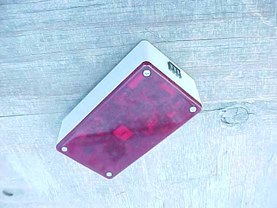
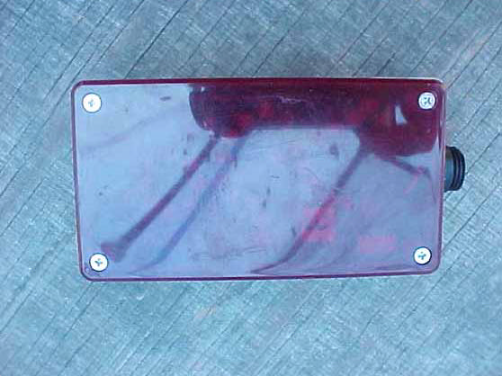
1 COPAR COPAR Corporation 5744 West 77 TH Street Burbank, Illinois 60459 U.S.A. Telephone: (708) 496-1859 FAX: (708) 496-0079 Email: [email protected] Web Site: http://www.copar.com NOTICE: Read this manual carefully before installing, operating or servicing this equipment. Failure to comply with the instructions may void the warranty. Manual #645-435 Created: 11/12/04 2 List of Equipment PART# ITEM MODEL QTY. 008-101Pedestrian TransmitterPT15 008-103Battery ChargerBC11 008-102Truck TransmitterTT12 008-100Truck Receiver (12VDC)TR12 270-926Power cable2 270-925Interconnect cable2 3 This system is intended to warn lift/clamp truck drivers when a pedestrian or another truck is nearby. Each truck is fitted with a front mounted receiver and rear mounted transmitter. Each truck transmits a unique ID code. The truck receiver displays the ID codes of all signals being received, including its own. Continually displaying its own ID code helps verify proper operation of each trucks receiver and transmitter. All pedestrian transmitters transmit the same ID code, which is different from any of the truck codes. The truck receiver displays a steady (non-flashing) image of a pedestrian when receiving a signal from any pedestrian transmitter. This image is also displayed at the truck transmitter, which is visible while driving backwards. Optionally, a flashing image of a pedestrian can be displayed when receiving a signal from another truck. A four bit dip switch located in each truck receiver (SW 1) and truck transmitter (SW 2) selects one of 15 possible truck ID codes. The factory setting of these switches is printed on a sticker that is visible through the red cover. A receiver with code 0 has this feature disabled. A receiver with the same code as its corresponding transmitter has this feature enabled. The gray power cable is used to supply 12 volts DC from the truck battery to the receiver, connect the RED wire to the positive terminal and the BLACK wire to the negative terminal. This cable has a locking feature, while pushing the plug into the receptacle twist it clockwise to lock it in place. To unplug this cable twist it counter-clockwise to unlock it. If the available voltage is greater than 12 use receiver model TRH1, which operates on voltages from 24 to 48 volts DC. This special receiver converts the higher truck voltage to 12 VDC for use by this system. The black interconnect cable goes from the receiver to the transmitter. Note the polarity of each end and match it to the corresponding connector. Secure each end with the blue threaded ring, similar to a garden hose. The pedestrian transmitters are normally stored on the battery charger. They can stay there indefinitely without overcharging the internal batteries. The pedestrian transmitter will automatically turn ON when removed form the charger. The image of a pedestrian will appear on the verification display located at the right side of the charger when a operating transmitter is held nearby. NOTE: the range of the verification display is intentionally very short to avoid detecting signals from elsewhere in the building. The Pedestrian transmitter is turned OFF when placed on the battery charger. During shipping and storage the Pedestrian transmitter is turned off by placing a small piece of conductive foam over the charging contacts and holding it in place with a rubber band. The RF output power of any pedestrian or truck transmitter can be adjusted by removing the front red cover and adjusting PT 3 located in the upper left corner to obtain the desired range (factory set to about 35 feet). Each transmitter transmits a fixed number of consecutive messages after which the RF carrier is turned off for approximately 1.2 seconds. This process is continually repeated while the transmitter is operating. The duration of each message is approximately 19 milliseconds. The number of consecutive messages is determined by switches SW 2 and SW 3. SW 2 is only provided on truck transmitters. NOTE: at least one bit of SW 2 must be ON. SW 3 is only provided on pedestrian transmitters. Each transmitter MUST transmit a unique number of messages to ensure proper operation when two or more transmitters are in close proximity. 4 There are 15 possible truck settings and 16 possible pedestrian settings, each produces a different number of consecutive messages, as shown below. The factory setting of each transmitter is printed on a sticker that is visible through the red cover. Truck transmitter labels show the ID code. Pedestrian transmitter labels show the switch position. Pedestrian transmitter settings Truck transmitter settings SW 3 (16 pos. rotary switch) Switchconsecutive SW 2 (4 bit dip switch)consecutiveTruckPositionmessages #1 #2 #3 #4messagesID code032 ONoffoffoff21134 offONoffoff42236 ONONoffoff612338 offoffONoff83440 ONoffONoff1013542 offONONoff1223644 ONONONoff14123746 offoffoffON164848 ONoffoffON1814950 offONoffON2024A52 ONONoffON22124B54 offoffONON2434C56 ONoffONON26134D58 offONONON`28234E60 ONONONON301234F62 5 DECLARATION OF CONFORMITY TRADE NAME: Radio Receiver MODEL NUMBER: TR 1 COMPLIANCE TEST REPORT NUMBER: B41012B1 COMPLIANCE TEST REPORT DATE: October 12 th 2004 RESPONSIBLE PARTY (IN USA): Copar Corporation ADDRESS: 5744 W. 77 th Street TELEPHONE: (708) 496-1859 This equipment has been tested and found to comply with the limits for a Class B digital device, pursuant to Part 15 of the FCC rules. These limits are designed to provide reasonable protection against harmful interference in a residential installation. This equipment generates, uses, and can radiate radio frequency energy and, if not installed and used in accordance with the instructions, may cause harmful interference to radio communications. However, there is no guarantee that interference will not occur in a particular installation. If the unit does cause harmful interference to radio to television reception, please refer to your users manual for instructions on correcting the pro…
Text truncated - open the document above for the full version.
scott To: [email protected]; [email protected] Subject: FCC ID: SMOTT1 12/7/2004 Mr. Fujimoto: In order for processing of this application (FCC ID: SMOTT1) to continue, the following issue(s) will have to be addressed: 1) When calculating the average value of a pulse operated emission which has a duty cycle of less than 100 ms, the calculations should be based on the on‐time over one complete pulse train, and not 100 ms, as is the case when the pulse train exceeds 100 ms. Please submit corrected calculations. 2) The average value of the emissions reported do not correlate to the values expected based on calculations based on the duty cycle plots. A 77% duty cycle was reported, but some of the average values reflect 4‐5 dB reduction from the peak level, corresponding to a duty cycle as low as 56%. Please explain. The item(s) indicated above must be submitted before processing can continue on the above referenced application. Failure to provide the requested information within 60 days of the original e‐mail date may result in application dismissal and forfeiture of the filing fee. Also, please note that partial responses increase processing time and should not be submitted. Please upload responses and/or exhibits to the electronic filing website. Your correspondence number is SMOTT1‐1. Best regards, Scott McCutchan Operations Manager Compatible Electronics TCB (714) 579‐0500 Direct: (714) 579‐1489 Fax: (714) 579‐1850 [email protected]
IC:5439A-PT1 FCC ID: SMOPT1 This device complies with Part 15 of the FCC Rules. Operation is subject to the two following conditions: (1) This device may not cause harmful interference and (2) This device must accept any interference received, including interference that may cause undesired operation. IC:5439A-TT1 FCC ID: SMOTT1 This device complies with Part 15 of the FCC Rules. Operation is subject to the two following conditions: (1) This device may not cause harmful interference and (2) This device must accept any interference received, including interference that may cause undesired operation. COPAR CORP.Model TR1 FCCTested To Comply With FCC Standards FOR HOME OR OFFICE USE This Class B digital apparatus meets all requirements of the Canadian Interference-Causing Equipment Regulations. Proposed FCC labels 2 x 2 Located on lower back of pedestrian transmitter below belt clip. 2 x 2 Located on center back of truck transmitter between Velcro mounting strips. 2 x 1 5/8 Located on center back of truck receiver between Velcro mounting strips. Page 1 of 1 11/2/04file://G:\Engineering\JJDoczy\temp\fcc_label.gif 1 7/8 CANADA : 109G 12021 7/16 Model/FCCID : ABCPT1
Report Number: B41028D1 FCC Part 15 Subpart B and FCC Section 15.249 Test Report Truck Transmitter Model: TT-1 Brea Division 114 Olinda Drive Brea, CA 92823 (714) 579-0500 Agoura Division 2337 Troutdale Drive Agoura, CA 91301 (818) 597-0600 Silverado Division 19121 El Toro Road Silverado, CA 92676 (949) 589-0700 Lake Forest Division 20621 Pascal Way Lake Forest, CA 92630 (949) 587-0400 Page 1 of 15 FCC PART 15, SUBPART B and C TEST REPORT for TRUCK TRANSMITTER MODEL: TT-1 Prepared for COPAR CORPORATION 5744 WEST 77 TH STREET BURBANK, ILLINOIS 60459-1305 Prepared by:_____________________ KYLE FUJIMOTO Approved by:____________________ MICHAEL CHRISTENSEN COMPATIBLE ELECTRONICS INC. 114 OLINDA DRIVE BREA, CALIFORNIA 92823 (714) 579-0500 DATE: NOVEMBER 1, 2004 REPORT APPENDICES TOTAL BODY A B C D E PAGES 15 2 2 2 12 21 54 This report shall not be reproduced except in full, without the written approval of Compatible Electronics. Report Number: B41028D1 FCC Part 15 Subpart B and FCC Section 15.249 Test Report Truck Transmitter Model: TT-1 Brea Division 114 Olinda Drive Brea, CA 92823 (714) 579-0500 Agoura Division 2337 Troutdale Drive Agoura, CA 91301 (818) 597-0600 Silverado Division 19121 El Toro Road Silverado, CA 92676 (949) 589-0700 Lake Forest Division 20621 Pascal Way Lake Forest, CA 92630 (949) 587-0400 Page 2 of 15 TABLE OF CONTENTS Section / Title PAGE GENERAL REPORT SUMMARY 4 SUMMARY OF TEST RESULTS 4 1. PURPOSE 5 2. ADMINISTRATIVE DATA 6 2.1 Location of Testing 6 2.2 Traceability Statement 6 2.3 Cognizant Personnel 6 2.4 Date Test Sample was Received 6 2.5 Disposition of the Test Sample 6 2.6 Abbreviations and Acronyms 6 3. APPLICABLE DOCUMENTS 7 4. DESCRIPTION OF TEST CONFIGURATION 8 4.1 Description Of Test Configuration - EMI 8 4.1.1 Cable Construction and Termination 9 5. LISTS OF EUT, ACCESSORIES AND TEST EQUIPMENT 10 5.1 EUT and Accessory List 10 5.2 EMI Test Equipment 11 6. TEST SITE DESCRIPTION 12 6.1 Test Facility Description 12 6.2 EUT Mounting, Bonding and Grounding 12 7. TEST PROCEDURES 13 7.1 Conducted Emissions Test 13 7.2 Radiated Emissions (Spurious and Harmonics) Test 14 8. CONCLUSIONS 15 Report Number: B41028D1 FCC Part 15 Subpart B and FCC Section 15.249 Test Report Truck Transmitter Model: TT-1 Brea Division 114 Olinda Drive Brea, CA 92823 (714) 579-0500 Agoura Division 2337 Troutdale Drive Agoura, CA 91301 (818) 597-0600 Silverado Division 19121 El Toro Road Silverado, CA 92676 (949) 589-0700 Lake Forest Division 20621 Pascal Way Lake Forest, CA 92630 (949) 587-0400 Page 3 of 15 LIST OF APPENDICES APPENDIX TITLE A Laboratory Recognitions B Modifications to the EUT C Additional Models Covered Under This Report D Diagrams, Charts, and Photos • Test Setup Diagrams • Radiated Emissions Photos • Antenna and Effective Gain Factors E Data Sheets LIST OF FIGURES FIGURE TITLE 1 Plot Map And Layout of Radiated Site Report Number: B41028D1 FCC Part 15 Subpart B and FCC Section 15.249 Test Report Truck Transmitter Model: TT-1 Brea Division 114 Olinda Drive Brea, CA 92823 (714) 579-0500 Agoura Division 2337 Troutdale Drive Agoura, CA 91301 (818) 597-0600 Silverado Division 19121 El Toro Road Silverado, CA 92676 (949) 589-0700 Lake Forest Division 20621 Pascal Way Lake Forest, CA 92630 (949) 587-0400 Page 4 of 15 GENERAL REPORT SUMMARY This electromagnetic emission test report is generated by Compatible Electronics Inc., which is an independent testing and consulting firm. The test report is based on testing performed by Compatible Electronics personnel according to the measurement procedures described in the test specifications given below and in the "Test Procedures" section of this report. The measurement data and conclusions appearing herein relate only to the sample tested and this report may not be reproduced without the written permission of Compatible Electronics, unless done so in full. This report must not be used to claim product endorsement by NVLAP, NIST or any other agency of the U.S. Government. Device Tested: Truck Transmitter Model: TT-1 S/N: N/A Product Description: See Expository Statement Modifications: The EUT was not modified in order to meet the specifications. Manufacturer: Copar Corporation 5744 West 77 th Street Burbank, Illinois 60459-1305 Test Dates: October 12, 27, and 28, 2004 Test Specifications : EMI requirements CFR Title 47, Part 15 Subpart B; and Subpart C, Sections 15.205, 15207, 15.209 and 15.249 Test Procedure: ANSI C63.4 Test Deviations: The test procedure was not deviated from during the testing. SUMMARY OF TEST RESULTS TEST DESCRIPTION RESULTS 1 Conducted RF Emissions, 150 kHz - 30 MHz This test was not performed because the EUT operates on 12 volts DC only and will never be plugged into the AC public mains. 2 Radiated RF Emissions, 10 kHz - 9300 MHz Complies with the Class B limits of CFR Title 47, Part 15, Subpart B; and Subpart C, sections 15.205, 15.209, and 15.249. Report Number: B41028D1 FCC Part 15 Subpart B and FCC Section 15.249 Test Report Truck Transmitter Model: TT-1 Brea Division 114 Olinda Drive Brea, CA 92823 (714) 579-0500 Agoura Division 2337 Troutdale Drive Agoura, CA 91301 (818) 597-0600 Silverado Division 19121 El Toro Road Silverado, CA 92676 (949) 589-0700 Lake Forest Division 20621 Pascal Way Lake Forest, CA 92630 (949) 587-0400 Page 5 of 15 1. PURPOSE This document is a qualification test report based on the Electromagnetic Interference (EMI) tests performed on the Truck Transmitter Model: TT-1. The EMI measurements were performed according to the measurement procedure described in ANSI C63.4. The tests were performed in order to determine whether the electromagnetic emissions from the equipment under test, referred to as EUT hereafter, are within the Class B specification limits defined by CFR Title 47, Part 15, Subpart B; and Subpart C, sections 15.205, 15.207, 15.209, and 15.249. Report Number: B41028D1 FCC Part 15 Subpart B and FCC Section 15.249 Test Report Truck Transmitter Model: TT-1 Brea Division 114 Ol…
Text truncated - open the document above for the full version.
RF Att 10 dB A Unit dB V Ref Lvl 102 dB V Ref Lvl 102 dB V RBW 50 kHz VBW 100 kHz IN1 P0 TDS SWT 5 ms Center 916.4008016 MHz500 s/ 1VIEW1AP 10 20 30 40 50 60 70 80 90 2 102 1 1 Delta 1 [T1] -1.64 dB 150.300601 s 1 [T1] 74.24 dB V 2.585170 ms 1 [T1] -1.64 dB 150.300601 s D1 54 dB V T2 → T1 Date: 12.OCT.2004 10:55:35 Time of One Small Pulse = 150.300601 uS RF Att 10 dB A Unit dB V Ref Lvl 102 dB V Ref Lvl 102 dB V RBW 50 kHz VBW 100 kHz IN1 P0 TDS SWT 5 ms Center 916.4008016 MHz500 s/ 1VIEW1AP 10 20 30 40 50 60 70 80 90 2 102 1 1 Delta 1 [T1] -0.77 dB 270.541082 s 1 [T1] 73.41 dB V 2.945892 ms 1 [T1] -0.77 dB 270.541082 s D1 54 dB V T2 → T1 Date: 12.OCT.2004 10:56:19 Time of One Large Pulse = 270.541082 uS RF Att 10 dB A Unit dB V Ref Lvl 102 dB V Ref Lvl 102 dB V RBW 50 kHz VBW 100 kHz IN1 P0 TDS SWT 10 ms Center 916.4008016 MHz1 ms/ 1VIEW1AP 10 20 30 40 50 60 70 80 90 2 102 1 1 Delta 1 [T1] 2.13 dB 4.388778 ms 1 [T1] 67.20 dB V 2.404810 ms 1 [T1] 2.13 dB 4.388778 ms D1 54.4 dB V T2 → T1 → Date: 12.OCT.2004 11:13:53 Time of One Extra Large Pulse = 4.388778 mS RF Att 10 dB A Unit dB V Ref Lvl 102 dB V Ref Lvl 102 dB V RBW 50 kHz VBW 100 kHz IN1 SWT 20 ms Center 916.4008016 MHz2 ms/ P0 TDS 1VIEW1AP 10 20 30 40 50 60 70 80 90 2 102 1 1 Delta 1 [T1] -1.35 dB 5.050100 ms 1 [T1] 68.88 dB V 3.847695 ms 1 [T1] -1.35 dB 5.050100 ms D1 54 dB V T2 T1 Date: 12.OCT.2004 11:04:35 Number of Small Pulses in 1 train = 10*150.300601 uS = 1.50300601 mS Number of Large Pulses in 1 train = 30*270.54082 uS = 8.1162246 mS Number of Extra Large Pulses in 1 train = 4.388778 mS RF Att 10 dB A Unit dB V Ref Lvl 102 dB V Ref Lvl 102 dB V RBW 50 kHz VBW 100 kHz IN1 P0 TDS SWT 120 ms Center 916.4008016 MHz12 ms/ 1VIEW1AP 10 20 30 40 50 60 70 80 90 2 102 1 2 1 Delta 1 [T1] -0.01 dB 100.040080 ms 1 [T1] 91.29 dB V 4.088176 ms 1 [T1] -0.01 dB 100.040080 ms 2 [T1] 91.21 dB V 101.482966 ms D1 54.4 dB V T1 T2 Date: 12.OCT.2004 11:35:10 120 mS Screen Shot to Show How the Pulses Repeat
114 Olinda Drive · Brea, California · United States
| # | Rule Parts | Frequency Range | Power Output |
|---|---|---|---|
| 1 | 15C | 916.5 MHz - 916.5 MHz | - |

Pedestrian Transmitter
Equipment Class
DXX - Part 15 Low Power Communication Device Transmitter