SMZBTM-D1A-AMonitoring Ear Thermometer
Rio Flexon Technology Co., Ltd.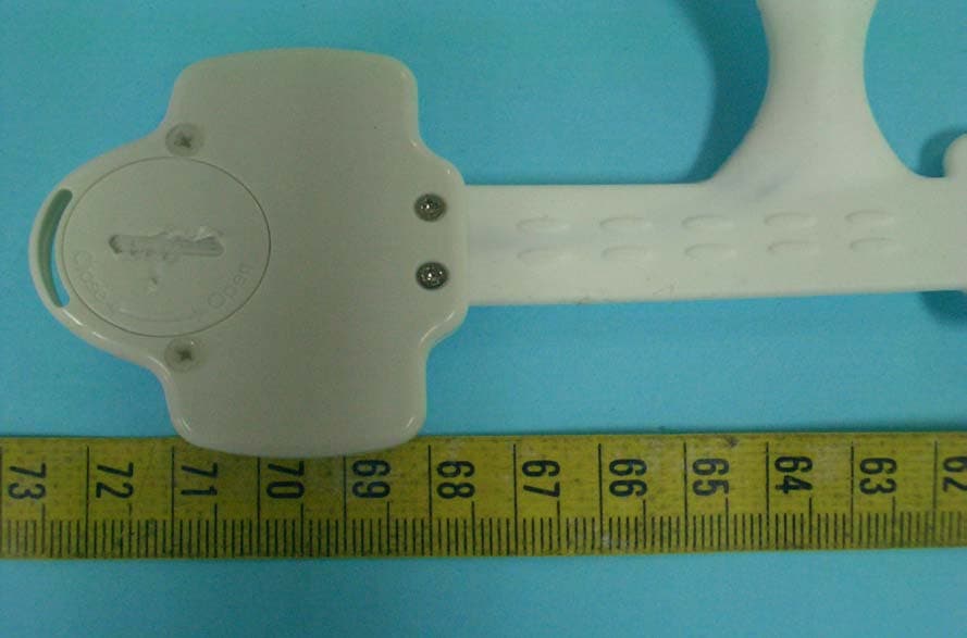
Click to zoom
Application Details
- Equipment Class
- DXT - Part 15 Low Power Transceiver, Rx Verified
- Date of Grant
- Jun 26, 2006
- Application Purpose
- Original Equipment
- Date of Application
- Jun 26, 2006
- Equipment Note
- Monitoring Ear Thermometer
- Frequency Range
- 2434.00000000 - 2476.00000000
- Country
- Taiwan
Documents & Files
Document Text
Text extracted from the exhibit documents filed with the FCC. Open a document above to read the original.
Users Manual
1 BTM-D1A Monitoring Ear Thermometer Product Instruction Manual 2 1. Introduction of BTM-D1A - Ear Thermometer Key Pads & Functions (1) The Receiver The instruction of the Keys and the Power Indicator: Ear Temperature Key: for the use of the ear temperature measuring Ok KeyLeft Key and right Key: for the use of the high/low temperature alarm setting Power Key: for the use of the lasting armpit temperature measuring Power Indicator: for the use of the easy identification of the Receiver at dark Note: This product is designed without a protective covering on the Ear Monitor. Clean with alcohol after each use. Left Key Right Key OK Key Power Key Ear Temperature Key Power Indicator 3 (2)The LCD Display of the Receiver (3) The Armband Battery Installation: Using a coin or screw-driver, turn counter-clockwise to open the battery cover. To close the cover turn clockwise. Note: This product is made of a silicone gel. Clean the product surface of the Armband using water and a tissue. Do not immerse Armband into water. Power Key Power Indicator Temperature Sensor Armpit Temperature Status Ear Temperature Indicator Elephant Indicator Temperature Indicator High/Low Temperature Alarm Setting Wireless Transmission Indicator Receiver Battery Indicator Armband Battery Indicator 4 2. Operating Instructions (1)Ear Temperature Measuring: Step 1. Press "Ear Temperature Key" for 2 seconds until the "Elephant Indicator" and the "Ear Temperature Indicator" begin to flash. Step 2. When the "Elephant Indicator" stops flashing it has a full power supply. Then, insert the Ear Monitor into the ear of the patient. Press and hold the "Ear Temperature Key" until it beeps once, and then record the ear temperature of the patient which is displayed on the screen. Step 3. The Receiver will turn off automatically after 15 seconds. Notes: The Receiver will turn off automatically in 30 seconds without any operation. (2)Armpit Temperature Measuring: uArmpit Temperature Measuring: Step 1.Press the "Power Key" for 2 seconds until the green light flashes every 4 seconds. Step 2. Repeat Step 1. The display will show armpit temperature. It also indicates that the wireless transmission is operating. Step 3. Place Temperature Sensor "face up" and fasten the Armband securely to upper-arm, near the armpit. Step 4. Record the patient's temperature. Allow 3 to 5 minutes to accurately assess temperature stability. The Display will show the current temperature readings every 12 seconds allowing the operator to accurately determine the average temperature of the patient. Step 5. To turn the Receiver off, press the "Power Key" for two seconds and wait for one "beep" to turn off Receiver Display screen. Remove Armband from patient's arm and press the "Power Key" and wait until the red light blinks once to indicate that the Armband is turned off. vTemperature Alarm Setting: The operator can set both high and low temperature alarm signals. When applicable, the Receiver will exhibit a series of "Beeps" alerting the operator to take appropriate action. The 5 alarm setting procedures are as follows: Step1. High temperature setting: Press the “OK Key” for 2 seconds then the Receiver Beeps twice to get into the temperature alarm setting mode. The Display shows “HI” and the Default figures flashing on it. Step2. Press “Right Key” or “Left Key” to adjust the alarm temperature setting. The temperature is adjusted by 0.5 (or 1a time such as 38.5,39,39.5 and so on, then press “OK Key” to finish setting. Step3. Low temperature setting: Repeat Step1, press the “OK Key,” when the “HI” and the Default figures flashing on it, to get into the “LO” and the Default figures flashing on the Display. Step4. Press “Right Key” or “Left Key” to adjust the alarm temperature setting (see Step 2). Note: ÆThe DefaultThe Default figures of the temperature alarm setting are HI38 and LO34 ( or HI100 and LO93) and the Receiver will take these figures as the Temperature Alarm Setting without any change in advance. The high temperature alarm ranges from 32 to 42 ( or 96 to 104); the low temperature alarm ranges from 32 to 34.5 ( or 89 to 96). ÆUnintentionally Pressing functionThe receiver will return to the temperature monitoring mode and without change any setting if the operations mentioned above are not finished within 10 seconds. ÆPriority Alarm processingThe product is designed to process the alarm situation prior to the temperature alarm setting model, or any other operations. Without saving any setting if not pressing the “OK Key.” the operator is better off to operate temperature alarm setting with the full power supply. ÆPlease re-set the High/Low temperature alarm setting after replacing the batteries, or the Receiver will get the default as the temperature alarm setting. w Check the High/Low temperature alarm setting: The figures of “HI” and “LO” on the LCD Display show the setting of the High/Low temperature alarm set by the operator. 6 xAbnormal Temperature Alarm: ÆAlarm The High/Low Temperature Alarm Setting of the Display will be flashing on the “HI” and “LO” and their related figures when the temperature of a patient out of the temperature alarm setting. That is, the “HI” and the figures are flashing and vice versa. The Receiver will “Beep, Beep, Beep, Beep” every 2 seconds to inform the operator to take adequate actions. ÆLasting alarmThe Receiver will check every 10 minutes the temperature of a patient if or not out of the temperature alarm setting. The Receiver will keep noticing the operator to take adequate actions via the lasting Beeps if out of the temperature alarm setting. Press any key on the Receiver to stop Beep alarm. Note 1. In case that the original temperature of the Receiver lowers the low temperature alarm setting then starts the alarm system, this product, when power on, will trigger the low temperature alarm system after the normal temperature higher than that of the low temperature alarm setting by 0.5. 2. It may cause low temperature alarm…
Text truncated - open the document above for the full version.
Cover Letter(s)
2 RIO FLEXON TECHNOLOGY CO.,LTD Compliance Certification Services Certification Division 561F Monterey Road Morgan Hill, CA 95037 To whom it may concern: We, the undersigned, hereby authorize ELECTRONICS TESTING CENTER, TAIWAN, to act on our behalf in all manners relating to application for equipment authorization, including signing of all documents relating to these matters. Any and all acts carried out by ELECTRONICS TESTING CENTER, TAIWAN on our behalf shall have the same effect as acts of our own. We, the undersigned, hereby certify that we are not subject to a denial of federal benefits, that includes FCC benefits, pursuant to Section 5301 of the Anti-Drug Abuse Act of 1988, 21 U.S.C. 853(a). In authorizing ELECTRONICS TESTING CENTER, TAIWAN as our agent, we still recognize that we are responsible to: a) comply with the relevant provisions of the certification program; b) make all necessary arrangements for the conduct of the evaluation, including provision for examining documentation and access to all areas, records (including internal audit reports) and personnel for the purposes of evaluation (e.g. testing, inspection, assessment, surveillance, reassessment) and resolution of complaints; c) make claims regarding certification only in respect of the scope for which certification has been granted; d) do not use our product certification in such a manner as to bring the Certification Division into disrepute and not make any statement regarding our product certification which the Certification Division may consider misleading or unauthorized; e) upon suspension or cancellation of certification, discontinue use of all advertising matter that contains any reference thereto and return any certification documents as required by the Certification Division; f) use certification only to indicate the products are certified as being in conformity with specified standards;
Cover Letter(s)
2 RIO FLEXON TECHNOLOGY CO.,LTD Federal Communications Commission FCC ID: SMZBTM-D1A-A Product Name: Monitoring Ear Thermometer Model Name: BTM-D1A-A Trade Name: RIO Dear Sir: In accordance with 47 C.F.R. Section 0.459, we would like to request confidentiality on some exhibits we submitted for above application for the reason of trade secret. If those exhibits are available for public inspection, any person who once gets the information contained in those exhibits will be able to design and to make the same products very easily. This is a very serious problem and huge loss for us, because we did invest so much on it. Please be not made the Exhibit Types listed below routinely available for public inspection: Block Diagram and Schematics By: By: Yang Chang Hua (Signature) (Printed) Title : R.D.Mamanger Applicant : RIO FLEXON TECHNOLOGY CO.,LTD Address : 15F., NO.868-2, Jhongjheng Rd., Jhonghe City, Taipei County 235, Taiwan (R.O.C) Tel : (02)8221-8199 Fax: (02)8221-8198 Date : 2006/04/27
Cover Letter(s)
1 Helen Zhao Subject:FW: FW: RIO FLEXON TECHNOLOGY CO.,LTD, FCC ID: SMZBTM-D1A-A, Assessment NO.: AN06T5890, Notice#1 Exhibit-E-User_Man ual_rev.pdf From: iris Sent: Monday, June 26, 2006 7:01 PM To: Helen Zhao Subject: Re: FW: RIO FLEXON TECHNOLOGY CO.,LTD, FCC ID: SMZBTM-D1A-A, Assessment NO.: AN06T5890, Notice#1 Dear Helen, Pls find the attached revised user manual. Best Regards, Iris Lin -----Original Message----- Sent: Friday, June 23, 2006 5:33 PM Subject: RIO FLEXON TECHNOLOGY CO.,LTD, FCC ID: SMZBTM-D1A-A, Assessment NO.: AN06T5890, Notice#1 Question #1: The user manual does not contain labelling requirement as specified in FCC 15.19. Please update the user manual. Best Regards, Helen Zhao The items indicated above must be submitted before processing can continue on the above referenced application. Failure to provide the requested information within 30 days of the original e-mail date may result in application dismissal and forfeiture of the filing fee. Also, please note that partial responses increase processing time and should not be submitted. Any questions about the content of this correspondence should be directed to the e-mail address listed below the name of the sender.
External Photos
ETC Report No. : 06-04-RBF-074-02 Sheet 1 of 3 Sheets FCC ID.: SMZBTM-D1A-A Rev. No 1.0 CONSTRUCTED PHOTOS of EUT 1. Top View of EUT 2. Bottom View of EUT
ID Label/Location Info
Monitoring Ear Thermometer Model No.: BTM-D1A-A FCC ID : SMZBTM-D1A-A 20mm 6mm
Internal Photos
ETC Report No. : 06-04-RBF-074-02 Sheet 2 of 3 Sheets FCC ID.: SMZBTM-D1A-A Rev. No 1.0 CONSTRUCTED PHOTOS of EUT 3. Internal View of EUT ETC Report No. : 06-04-RBF-074-02 Sheet 3 of 3 Sheets FCC ID.: SMZBTM-D1A-A Rev. No 1.0 CONSTRUCTED PHOTOS of EUT 4. Component View of Main PCB 5. Solder View of Main PCB
Operational Description
Instructions 1.Usage: The Monitoring Ear Thermometer, the Receiver with new generation, is well designed to measure immediately the ear temperature of the infants, babies, and disable elderly, etc. when each of them has a cold or flue, and also needs to be taken care of overnight. The Receiver will be Beeping continuously to alarm the operator to take some adequate actions. The body sensor can be used for a longer period monitoring if abnormal temperature found. 2. Principle of Operation: A.The Receiver: a. Ear temperature measuring: DC – DC starts offering power to the ear temperature mode when pressing “Ear Temperature Key.” MCU communicates with the ear temperature mode by RS232 mode. The measured figures received by the Receiver are shown on the LCD. MCU shuts down automatically after operating by 15 seconds. b. Two-way wireless transmission: The receiver will command the body sensor via the two-way wireless transmission. The body sensor sends the measuring such as body temperature and power supply etc, back to the Receiver. The Receiver shows these figures via adequate processing from the measuring, flashing on the LCD, and Beeping continuously if the temperature out of the setting ranges. c. Low power supply alarm: Both the Receiver and the body sensor are self-detectable functioning to the power supply. The Receiver will be flashing, if low power supply, on the “Power Supply Indicator” of the LCD, and Beeping continuously the operator to change the batteries. B. The body sensor: The measuring comes from the body sensor attached on the armpit will be translated, via A/D, form MCU into body temperature, and then sends to the Receiver. 3. The design and the manufacturing of the circuit of this product: This product is designed to use less parts via SMD parts and One Chip micro-control on the circuit not only to reduce the manufacturing cost and to save power supply, but also to become more competitive. The manufacturing process via SMT technique is to improve the yield rate. The wireless transmission is also designed to use the Chip to save the production process adjustment, as well as to avoid the mistakes from manufacturing process affecting the quality of this product.
Test Report
Rev. No 1.0 FCC Part 15 EMI TEST REPORT of E.U.T. : Monitoring Ear Thermometer FCC ID : SMZBTM-D1A-A MODEL : BTM-D1A-A for APPLICANT : RIO FLEXON TECHNOLOGY CO., LTD ADDRESS : 15F., NO.868-2, Jhongjheng Rd., Jhonghe City, Taipei County 235, Taiwan (R.O.C) Test Performed by ELECTRONICS TESTING CENTER, TAIWAN NO. 34. LIN 5. DINGFU TSUEN, LINKOU SHIANG TAIPEI COUNTY, TAIWAN, 24442, R.O.C. Tel:(02)26023052 Fax:(02)26010910 http://www.etc.org.tw ; e-mail : [email protected] Report Number : 06-04-RBF-074-02 ETC Report No. : 06-04-RBF-074-02 FCC ID. : SMZBTM-D1A-A Rev. No 1.0 TEST REPORT CERTIFICATION Applicant : RIO FLEXON TECHNOLOGY CO., LTD 15F., NO.868-2, Jhongjheng Rd., Jhonghe City, Taipei County 235, Taiwan (R.O.C) Manufacturer : Taidoc Technology Corp. 4F, NO.88. Sec.1, Kwang-Fu RD., San-Chung, Taipei County, Taiwan Description of EUT : a) Type of EUT : Monitoring Ear Thermometer b) Trade Name : RIO c) Model No. : BTM-D1A-A d) Power Supply : DC 3.0V e) Frequency Range : 2434.000-2476.000 MHz Regulation Applied : FCC Rules and Regulations Part 15 Subpart C (2005) I HEREBY CERTIFY THAT: The data shown in this report were made in accordance with the procedures given in ANSI C63.4 (2003), and the energy emitted by the device was founded to be within the limits applicable. I assume full responsibility for accuracy and completeness of these data. Note: 1. The result of the testing report relate only to the item tested. 2. The testing report shall not be reproduced expect in full, without the written approval of ETC. Issued Date : Jun. 15, 2006 Test Engineer : ( Kevin Lee ) Approve & Authorized Signer : Will Yauo, Manager EMC Dept. II of ELECTRONICS TESTING CENTER, TAIWAN ETC Report No. : 06-04-RBF-074-02 FCC ID. : SMZBTM-D1A-A Rev. No 1.0 Table of Contents Page 1 GENERAL INFORMATION ...................................................................................................... 1 1.1 Product Description...................................................................................................................... 1 1.2 Characteristics of Device ............................................................................................................. 1 1.3 Test Methodology......................................................................................................................... 1 1.4 Test Facility.................................................................................................................................. 1 2 PROVISIONS APPLICABLE ..................................................................................................... 2 2.1 Definition ..................................................................................................................................... 2 2.2 Requirement for Compliance ....................................................................................................... 3 2.3 Restricted Bands of Operation ..................................................................................................... 5 2.4 Labeling Requirement .................................................................................................................. 5 2.5 User Information .......................................................................................................................... 6 3 SYSTEM TEST CONFIGURATION ......................................................................................... 7 3.1 Justification .................................................................................................................................. 7 3.2 Devices for Tested System ........................................................................................................... 7 4 RADIATED EMISSION MEASUREMENT ............................................................................. 8 4.1 Applicable Standard ..................................................................................................................... 8 4.2 Measurement Procedure ............................................................................................................... 8 4.3 Measuring Instrument................................................................................................................. 10 4.4 Radiated Emission Data ............................................................................................................. 11 4.5 Field Strength Calculation.......................................................................................................... 16 4.6 Photos of Radiation Measuring Setup ........................................................................................ 17 5 CONDUCTED EMISSION MEASUREMENT ....................................................................... 18 5.1 Standard Applicable ................................................................................................................... 18 6 ANTENNA REQUIREMENT ................................................................................................... 19 6.1 Standard Applicable ................................................................................................................... 19 6.2 Antenna Construction................................................................................................................. 19 7 BAND EDGES MEASUREMENT ............................................................................................ 20 7.1 Standard Applicable ................................................................................................................... 20 7.2 Measurement Procedure ............................................................................................................. 20 7.3 Measurement Equipment............................................................................................................ 20 7.4 Measurement Data.......................................................................................…
Text truncated - open the document above for the full version.
Test Setup Photos
ETC Report No. : 06-04-RBF-074-02 Sheet 17 of 22 Sheets FCC ID.: SMZBTM-D1A-A Rev. No 1.0 4.6 Photos of Radiation Measuring Setup
Contact Information
Applicant
Jeff Liao(General manager)
Test Firm
Electronics Testing Center, TaiwanWill Yauo
Technical Specifications
| # | Rule Parts | Frequency Range | Power Output |
|---|---|---|---|
| 1 | 15C | 2.43 GHz - 2.48 GHz | - |