SQ6ECGMINIECG MINI
LifeWatch LTD.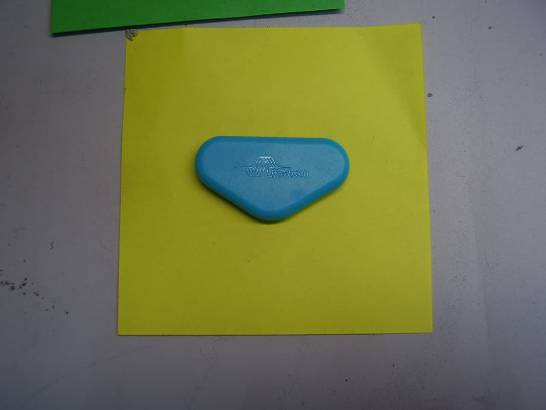
Click to zoom
Application Details
- Equipment Class
- DXT - Part 15 Low Power Transceiver, Rx Verified
- Date of Grant
- Apr 13, 2015
- Application Purpose
- Original Equipment
- Date of Application
- Apr 13, 2015
- Equipment Note
- ECG MINI
- Frequency Range
- 2404.00000000 - 2480.00000000
- Company
- LifeWatch LTD.
- Country
- Israel
Documents & Files
Document Text
Text extracted from the exhibit documents filed with the FCC. Open a document above to read the original.
Users Manual
ECG Mini User Guide ECG Mini User Guide PLEASE CALL 1.800.517.6330 FOR 24/7 CUSTOMER SUPPORT Page 2 ECG Mini User Guide This user guide includes information and instructions about the ECG Mini (Continuous ECG Monitor and Arrhythmia Detector) monitoring system. Please read it carefully before you begin testing. If you have any questions regarding the ECG Mini please contact LifeWatch at 1-800-517-6330. Federal Law (USA) restricts this device to sale by or on the order of a practitioner licensed by the law of the State in which he/she practices to use or order the use of the device. CAUTION: This manual should always accompany the unit. All personnel utilizing the ECG Mini system must have read and be familiar with the contents of this manual. First time use – You must call LifeWatch to receive instructions on how to proceed for the first time use. The first time the ECG Mini is activated and is attached to you, it will display screens that are not seen in regular use. These screens are calibration procedures the ECG Mini needs to perform to adjust its operation for first time use. Page 3 Authorized representatives: USA LifeWatch, Inc. O’Hare International Center 10255 West Higgins Road Suite 120 Rosemont, IL 60018 Tel: 847-720-2295 Fax: 847-720-1995 Toll Free: 800-633-3361 Fax: 800-954-2375 Email: [email protected] Israel LifeWatch Technologies Ltd. 2 Pekeris Street. Rehovot 7670202 Israel Tel: 972 8 9484000 Fax: 972 8 9484044 Email: [email protected] Copyright Declaration Copyright © 2015 LifeWatch Services, Inc. All rights reserved. LifeWatch, Watching Life, LifeStar and ECG Mini are trademarks of LifeWatch Services, Inc. LifeWatch reserves the right to change specifications at any time without notice. LifeWatch Technologies, LifeWatch Technologies logo and ECG Mini are trademarks or registered trademarks of the LifeWatch® Group of Companies. Page 4 All other brand names and product names used in this document are trade names, service marks, trademarks, or registered trademarks of their respective owners. The information and screens provided in this manual are subject to change without notice. LifeWatch Technologies Ltd. SHALL NOT BE LIABLE FOR TECHNICAL OR EDITORIAL ERRORS OR OMISSIONS CONTAINED HEREIN; NOR FOR INCIDENTAL OR CONSEQUENTIAL DAMAGES RESULTING FROM THE FURNISHING, PERFORMANCE, OR USE OF THIS MATERIAL. Illustrations included in this manual are general representations only and are not meant to comply with specific regulatory requirements. ATTENTION: The ECG Mini is a near diagnostic tool only and is not part of an emergency service. Heart strips transmitted by the device are not viewed immediately by technicians. If when viewed, the technician sees an arrhythmia that is potentially harmful or life threatening, LifeWatch will attempt to facilitate care for the patient through either their doctor or an emergency medical service, although this care may be delayed. Page 5 Table of Contents 1 Introduction ............................................................... 8 1.1 INTENDED USE ................................................... 8 1.2 GENERAL DESCRIPTION ...................................... 9 1.3 SYMBOLS ON EQUIPMENT AND LABELING ............ 11 1.4 WARNINGS AND CAUTIONS ................................ 13 1.5 GLOSSARY ....................................................... 19 2 General Description ............................................... 20 3 The ECG Mini Kit .................................................... 22 3.1 GATEWAY PHYSICAL DESCRIPTION ..................... 23 HOW MUCH CHARGE IS IN THE BATTERY? ...................... 24 4 Important Information Before Use ....................... 26 4.1 GENERAL ......................................................... 26 4.2 NO CONNECTION WITH GATEWAY CELLULAR DEVICE ....................................................... 26 5 Using the ECG Mini ................................................ 27 5.1 BEFORE STARTING............................................ 27 5.2 RECHARGING THE GATEWAY CELLULAR DEVICE ....................................................... 29 6 Using the ECG Mini System .................................. 30 6.1 GENERAL ......................................................... 30 6.2 INITIALIZING THE ECG MINI KIT .......................... 30 6.3 PLACING THE PATCH ......................................... 30 6.4 INSTALLING THE ECG MINI TRANSMITTER ........... 33 6.5 REMOVING THE ECG MINI ................................. 34 7 Using the Gateway Application ............................ 35 Page 6 7.1 STARTING THE APPLICATION .............................. 35 7.2 ECG MINI SCREEN ........................................... 36 7.3 GATEWAY NOTIFICATIONS.................................. 39 8 Heart Rate Calculation Method ............................. 42 8.1 INTRODUCTION.................................................. 42 8.2 METHOD OF CALCULATION ................................. 42 9 Pause Calculation ................................................... 42 10 Care .......................................................................... 43 10.1 CONDITIONS OF USE ....................................... 43 10.2 CLEANING ...................................................... 43 10.3 ENVIRONMENTAL CONSIDERATIONS ................. 43 11 Troubleshooting ..................................................... 44 12 Maintenance ............................................................ 45 12.1 CONDITIONS OF USE ....................................... 45 12.2 CARING FOR YOUR ECG MINI .......................... 45 12.3 PREVENTIVE MAINTENANCE............................. 46 13 Technical Specifications ....................................... 47 13.1 ECG MINI TECHNICAL SPECIFICATIONS ............ 48 Appendix A Monitor (Cellular Phone) Warnings ........ 51 FCC Radio Frequency Interference Statement .......... 56 Page 7 Table of Figures Figure 1 – Gateway Physical Description ........................ 23 Figure 1…
Text truncated - open the document above for the full version.
External Photos
External photos
ID Label/Location Info
DWG NO. LA-00143 DWG REV 03 ASHER K SHIMON M 01-03-15 LifeWatch Technologies Ltd. ECG Mini Brain (Transmitter) Label Label Rev ECO Description Date 01 03738 Initial 01-03-15 Notes: 1. Generic logo, material white polyester 2. Solvent resistant 3. Background color white 4. Print color: Black except for symbol 5. Material in accordance with RHoS 2011/65/EU Pantone 7462 C Pantone White C 0A 03644 Draft 05-01-15 32.4 14.27 mm 1:1 LA-00143 rev 03 FCC ID: SQ6ECGMINI S/N NOTE: barcode is comprised of the following information: xx |xx| xx | xxxx ww|yy|product code|serial number Placement and printing of serial number and FCC ID Serial number FCC ID 02 03785 Label material changed to white 25-03-15 LA-00143 rev 03 FCC ID: SQ6ECGMINI S/N LA-00143 rev 03 03 03800 FCC ID in one line 12-04-15
Internal Photos
Internal photos
Test Report
Test Report No. 9412334074 Applicant : LifeWatch Technologies Ltd. Equipment Under Test: ECG Mini Models: FGL-00030 FCC ID: SQ6ECGMINI From The Standards Institution Of Israel Industry Division Electronics & Telematics Laboratory EMC Branch ACLASS Accreditation Services Certificate Number: AT-1359 Test Report No.: 9412334074 Page 2 of 27 pages Title: ECG Mini Model: FGL-00030 FCC ID: SQ6ECGMINI Description of Equipment Under Test (EUT): ECG Mini. Models: FGL-00030 Software version of brain unit 1.2.0.0 Hardware version of brain unit PAL-00157 rev.0E Manufactured by: LifeWatch Technologies Ltd. Reference Documents: CFR 47 FCC: Rules and Regulations; Part 15. “Radio frequency devices”; Subpart C : “Intentional radiators” (2015). Section 15.209. “Radiated emission limits, general requirements”. “Radiated Emission Limits, Additional Provisions”; Section 15.249. “Operation within the bands 902 – 928 MHz, 2400 – 2483.5 MHz, 5725 – 5875 MHz and 24.0 - 24.25 GHz”. . Applicant: LifeWatch Technologies Ltd. Address: 2 Pekeris St., P.O.Box 527, Rehovot, 76100 Israel Sample for test selected by: The customer The date of tests: 1 March 2015 This Test Report contains 27 pages and may be used only in full. This Test Report applies only to the specimen tested and may not be applied to other specimens of the same product. Test Report No.: 9412334074 Page 3 of 27 pages Title: ECG Mini Model: FGL-00030 FCC ID: SQ6ECGMINI Table of Contents 1. EUT Description and operation 4 1.1. General description: 4 2. Test summary 5 2.1. Potential emission sources: 7 2.2. EUT setup and operation: 7 3. Measurements and derived results 7 3.1. Location of the Test Site: 7 3.2. Test condition: 7 3.3. Radiated emission test. 8 3.4. Test of field strength emission from intentional radiator. 9 3.5. Test of occupied bandwidth per 15.215(c) 21 4. Appendix 1. Test equipment used 22 5. Appendix 2: Antenna Factor and Cable Loss 23 6. Appendix 3: Test setups photo. 27 Test Report No.: 9412334074 Page 4 of 27 pages Title: ECG Mini Model: FGL-00030 FCC ID: SQ6ECGMINI 1. EUT Description and operation 1.1. General description: * Note: the customer supplied all information in clause below. The EUT, a Main Processing Unit (Brain, p/n FGL-00030), plugs into a cradle on the Patch with a 8-pin connector. The Brain receives the power from the Patch’s 1.4V battery. The Brain transmits data to the Gateway application using the RF component. The device uses NORDIC nRF24L01 single chip 2.4 GHz transceiver operating in 2400-2483.5 MHz frequency band. Type of modulation: GFSK Output power: programmed as 0, -6, -12 or -18 dBm Antenna type: Internal on PCB The EUT external view is presented in photo # 1. Photo 1. Brain inside patch view. Test Report No.: 9412334074 Page 5 of 27 pages Title: ECG Mini Model: FGL-00030 FCC ID: SQ6ECGMINI 2. Test summary Parameter FCC Part 15 Reference paragraph Verdict Test of field strength emission from intentional radiators “Radiated Emission Limits, Additional Provisions”; Section 15.249. Comply Electronics & Telematics Laboratory March 2015 Name: Eng. Yuri Rozenberg Name: Michael Feldman Position: Head of EMC Branch Position: Test Technician Measurement uncertainty. The test equipment has been calibrated according to its recommended procedures and is within the manufacturer's published limit of error. The laboratory calibrates its standards by a third party (traceable to NIST, USA) on a regular basis according to equipment manufacturer requirements. In the following table the uncertainty calculation is given. Type of disturbance Test description Calculated uncertainty U LAB Radiated disturbance electric field strength in a SAR at 3 m distance 9kHz – 30MHz 30 MHz – 1.0 GHz ±2.54 dB ±4.32 dB electric field strength in a FAR at 3 m distance 1.0 – 18 GHz. 18 – 40 GHz. ±4.47 dB ±2.78 dB Test Report No.: 9412334074 Page 6 of 27 pages Title: ECG Mini Model: FGL-00030 FCC ID: SQ6ECGMINI Normative References. FCC 47 CFR Part 15, Subpart C, 2015 Radio Frequency Devices Subpart C – Intentional Radiators ANSI C63.4: 2009 American National Standard for Method of Measurements of Radio-Noise Emissions from Low-Voltage Electrical and Electronic Equipment in the Range of 9 kHz to 40 GHz ANSI C63.10: 2009 American National Standard for Testing of Unlicensed Wireless Devices. Test Report No.: 9412334074 Page 7 of 27 pages Title: ECG Mini Model: FGL-00030 FCC ID: SQ6ECGMINI 2.1. Potential emission sources: The potential emission sources are detailed in Table 1. Table 1. Potential emission sources Frequency Location 16.384 MHz Microcontroller oscillator 16.0 MHz RF Lo oscillator 2404 - 2480 MHz RF signal 2.2. EUT setup and operation: Test was performed in continuous transmission mode at three points - low - 2404 MHz, middle - 2440 MHz and top - 2480 MHz of 2400 – 2483.5 MHz frequency band. 3. Measurements and derived results 3.1. Location of the Test Site: Radiated test was conducted at the EMC laboratory of the Standards Institution of Israel in Tel-Aviv. 3.2. Test condition: Temperature: 22 C. Humidity: 49 %. Atmospheric pressure: 1009 mbar. Test Report No.: 9412334074 Page 8 of 27 pages Title: ECG Mini Model: FGL-00030 FCC ID: SQ6ECGMINI 3.3. Radiated emission test. 3.3.1. General: Per FCC Part 15 Subpart C Sections 15.209, 15.249. Initial scans were made using a peak detector but still using the appropriate ANSI IF bandwidth. A tolerance limit was set 10 dB below the specification limit. Levels above the tolerance limit were retested using the Peak, QP or Average detectors. 3.3.2. Radiated emission measurements: Preliminary investigation was performed from the lowest radio frequency signal generated in the equipment up to ten harmonic of a carrier frequency. The final radiated emission measurements were performed in the semi Anechoic chamber at the 1 or 3 m test distances. Test was started with a new fresh battery. Measured voltage was 1.4VDC. The EUT was operated in continue transmition mode. The transmitter was installed on …
Text truncated - open the document above for the full version.
Test Setup Photos
Test set up photos
Contact Information
Applicant
Asher Kassel
Test Firm
The Standards Institution of IsraelYuri Rozenberg
Technical Specifications
| # | Rule Parts | Frequency Range | Power Output |
|---|---|---|---|
| 1 | 15C | 2.40 GHz - 2.48 GHz | - |
Other Applications from LifeWatch LTD.
SQ6VSPS
Jul 09, 2013Vital Signs Patch
Equipment Class
DXT - Part 15 Low Power Transceiver, Rx Verified