SRGS300SE-THUD
Chune E. Develop Group Ltd.
Click to zoom
Application Details
- Equipment Class
- DSC - Part 15 Security/Remote Control Transmitter
- Date of Grant
- Apr 28, 2013
- Application Purpose
- Original Equipment
- Date of Application
- Apr 28, 2013
- Equipment Note
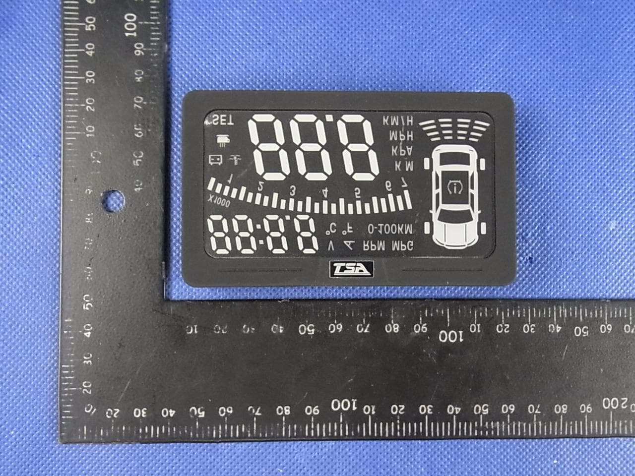
- HUD
- Frequency Range
- 433.92000000 - 433.92000000
- Company
- Chune E. Develop Group Ltd.
- Country
- Taiwan
Documents & Files
Document Text
Text extracted from the exhibit documents filed with the FCC. Open a document above to read the original.
Users Manual
TIRE PRESSURE MONITORING SYSTEM (TPMS) Each tire, including the spare (if provided), should be checked monthly when cold and inflated to the inflation pressure recommended by the vehicle manufacturer on the vehicle placard or tire inflation pressure label. (If your vehicle has tires of a different size than the size indicated on the vehicle placard or tire inflation pressure label, you should determine the proper tire inflation pressure for those tires.) As an added safety feature, your vehicle has been equipped with a tire pressure monitoring system (TPMS) that illuminates a low tire pressure telltale when one or more of your tires is significantly under-inflated. Accordingly, when the low tire pressure telltale illuminates, you should stop and check your tires as soon as possible, and inflate them to the proper pressure. Driving on a significantly under-inflated tire causes the tire to overheat and can lead to tire failure. Under-inflation also reduces fuel efficiency and tire tread life, and may affect the vehicle’s handling and stopping ability. Please note that the TPMS is not a substitute for proper tire maintenance, and it is the driver’s responsibility to maintain correct tire pressure, even if under-inflation has not reached the level to trigger illumination of the TPMS low tire pressure telltale. Your vehicle has also been equipped with a TPMS malfunction indicator to indicate when the system is not operating properly. The TPMS malfunction indicator is combined with the low tire pressure telltale. When the system detects a malfunction, the telltale will flash for approximately one minute and then remain continuously illuminated. This sequence will continue upon subsequent vehicle start-ups as long as the malfunction exists. When the malfunction indicator is illuminated, the system may not be able to detect or signal low tire pressure as intended. TPMS malfunctions may occur for a variety of reasons, including the installation of replacement or alternate tires or wheels on the vehicle that prevent the TPMS from functioning properly. Always check the TPMS malfunction telltale after replacing one or more tires or wheels on your vehicle to ensure that the replacement or alternate tires and wheels allow the TPMS to continue to function properly. The Tire Pressure Monitoring System complies with part 15 of the FCC rules and with RSS-210 of Industry Canada. Operation is subject to the Tires, Wheels and Loading 187 2010 Escape(204) Owners Guide, 2nd Printing USA(fus) following two conditions: (1) This device may not cause harmful interference, and (2) This device must accept any interference received, including interference that may cause undesired operation. WARNING:The Tire Pressure Monitoring System is NOT a substitute for manually checking tire pressure. The tire pressure should be checked periodically (at least monthly) using a tire gauge, seeInflating your tiresin this chapter. Failure to properly maintain your tire pressure could increase the risk of tire failure, loss of control, vehicle rollover and personal injury. Changing tires with TPMS Each road tire is equipped with a tire pressure sensor located inside the tire/wheel cavity. The pressure sensor is attached to the valve stem. The pressure sensor is covered by the tire and is not visible unless the tire is removed. Care must be taken when changing the tire to avoid damaging the sensor.It is recommended that you always have your tires serviced by an authorized dealer. The tire pressure should be checked periodically (at least monthly) using an accurate tire gauge, refer toInflating your tiresin this chapter. Understanding your Tire Pressure Monitoring System (TPMS) The Tire Pressure Monitoring System measures pressure in your four road tires and sends the tire pressure readings to your vehicle. The Low Tire Pressure Warning Lamp will turn ON if the tire pressure is significantly low. Once the light is illuminated, your tires are under inflated and need to be inflated to the manufacturer’s recommended tire pressure. Even if the light turns ON and a short time later turns OFF, your tire pressure still needs to be checked. Visit www.checkmytires.org for additional information. When your temporary spare tire is installed When one of your road tires needs to be replaced with the temporary spare, the TPMS system will continue to identify an issue to remind you that the damaged road wheel/tire needs to be repaired and put back on your vehicle. Tires, Wheels and Loading 188 2010 Escape(204) Owners Guide, 2nd Printing USA(fus) To restore the full functionality of the Tire Pressure Monitoring System, have the damaged road wheel/tire repaired and remounted on your vehicle. For additional information, refer toChanging tires with TPMS in this section. When you believe your system is not operating properly The main function of the Tire Pressure Monitoring System is to warn you when your tires need air. It can also warn you in the event the system is no longer capable of functioning as intended. Please refer to the following chart for information concerning your Tire Pressure Monitoring System: Low Tire Pressure Warning Light Possible cause Customer Action Required Solid Warning LightTire(s) under-inflated 1. Check your tire pressure to ensure tires are properly inflated; refer toInflating your tiresin this chapter. 2. After inflating your tires to the manufacturer’s recommended inflation pressure as shown on the Tire Label (located on the edge of driver’s door or the B-Pillar), the vehicle must be driven for at least two minutes over 20 mph (32 km/h) before the light will turn OFF. Spare tire in use Your temporary spare tire is in use. Repair the damaged road wheel/tire and reinstall it on the vehicle to restore system functionality. For a description on how the system functions, refer to When your temporary spare tire is installedin this section. TPMS malfunction If your tires are properly inflated and your spare tire is not in use and…
Text truncated - open the document above for the full version.
Cover Letter(s)
SCS-F18: Project and Product Certification Representative Authorization Letter Page 1 of 2 Rev 3.0 775 Montague Expressway Milpitas, CA 95035 Tel: 408-526-1188 Fax: 408-526-1088 Email: [email protected] Project and Product Certification Representative Authorization Letter Reason for Amendment (current / obsolete) Revision History Approved Date From To Initial Release (obsolete) 1.0 1.0 Nov-14-2006 Revised wording (obsolete) 1.0 2.0 Sept–25-2007 Updated company template (current) 2.0 3.0 Jan-31-2012 SCS-F18: Project and Product Certification Representative Authorization Letter Page 2 of 2 Rev 3.0 2013/04/10 To: SIEMIC, INC. 775 Montague Expressway, Milpitas, CA 95035 USA Dear Sir/Madam, Re: Project and Product Certification Representative Authorization Letter We, _____ Chune E. Develop Group Ltd._ _____hereby authorize SIEMIC, INC. to act as a Certification Body for certifying for the following project(s): Product: HUD Trade Name: N/A Model Name: S300SE-T Serial Model: S300SE FCC ID SRGS300SE-T We affirm that between SIEMIC and ___ Chune E. Develop Group Ltd.___, any difference in understanding, including test plan, measurement methods, applicable standards and relevant procedures and processes have been resolved prior to commencement of testing activities. Sincerely, Client’s signature Client’s name / title : Li Jianzhan/Manger Contact information / address : 4F., No.75, Sec. 1, Shuiyuan St., Tamsui Dist., New Taipei City 251, Taiwan
Cover Letter(s)
SCS-F19: Confidentiality Request Letter Page 1 of 2 Rev 3.0 775 Montague Expressway Milpitas, CA 95035 Tel: 408-526-1188 Fax: 408-526-1088 Email: [email protected] Confidentiality Request Letter Reason for Amendment (current / obsolete) Revision History Approved Date From To Initial Release (obsolete) 1.0 1.0 Nov-14-2006 Adding CFR 2.459 (obsolete) 1.0 2.0 August – 11 - 2008 Updated company template & Added text box (current) 2.0 3.0 Jan-31-2012 SCS-F19: Confidentiality Request Letter Page 2 of 2 Rev 3.0 2013/04/10 To: Federal Communications Commission Authorization and Evaluation Division 7435 Oakland Mills Road Columbia, MD Subject: Permanent Confidentiality Request for FCC ID: SRGS300SE-T We hereby request confidential treatment of information accompanying this application as outlined below: - Block Diagram - Schematics - Operational Description The above materials contain trade secrets and proprietary information not customarily released to the public. The public disclosure of these materials may be harmful to the applicant and provide unjustified benefits to its competitors. The applicant understands that pursuant to Section 0.457 & 0.459 of the Rules, disclosure of this application and all accompanying documentation will not be made before the date of the Grant for this application. Sincerely, Client’s signature Client’s name / title : Li Jianzhan/Manger Contact information / address : 4F., No.75, Sec. 1, Shuiyuan St., Tamsui Dist., New Taipei City 251, Taiwan
Cover Letter(s)
Model Difference HUD Model colour S300SE-T Black S300SE Black All the models are identical except the model name. Client’s name / title : Li Jianzhan/Manger Contact information / address : 4F., No.75, Sec. 1, Shuiyuan St., Tamsui Dist., New Taipei City 251, Taiwan
External Photos
APPENDIX-PHOTOGRAPHS OF EUT CONSTRUCTIONAL DETAILS Photo 1 Photo 2 Photo 3 Photo 4 Photo 5 Photo 6
ID Label/Location Info
W*H=2*0.3CM FCC ID:SRGS300SE-T
Internal Photos
Photo 7 Photo 8 Photo 9 Photo 10 Photo 11
Test Report
FCC RADIO TEST REPORT FCC ID: SRGS300SE-T Product: HUD Trade Name: N/A Model Name: S300SE-T Serial Model: S300SE Report No.: NTEK-2013NT0412076F Prepared for Chune E. Develop Group Ltd. 4F., No.75, Sec. 1, Shuiyuan St., Tamsui Dist., New Taipei City 251, Taiwan Prepared by Shenzhen NTEK Testing Technology Co., Ltd. 1/F, Building E, Fenda Science Park, Sanwei Community,Xixiang Street Bao’an District, Shenzhen P.R. China Tel.: +86-0755-61156588 Fax.: +86-0755-61156599 Website:www.ntek.org.cn Page 2 of 27 Report No.: NTEK-2013NT0412076F ` TEST RESULT CERTIFICATION Applicant’s name ................. : Chune E. Develop Group Ltd. Address ................................. : 4F., No.75, Sec. 1, Shuiyuan St., Tamsui Dist., New Taipei City 251, Taiwan Manufacturer........................ Chune E. Develop Group Ltd. Address.............................. 4F., No.75, Sec. 1, Shuiyuan St., Tamsui Dist., New Taipei City 251, Taiwan Product description Product name............................ : HUD Model and/or type reference : S300SE-T Serial Model: S300SE Rating(s) ................................ : DC 3V Standards ............................. : FCC Part15.231 Test procedure ............................... : ANSI C63.4-2003 This device described above has been tested by NTEK, and the test results show that the equipment under test (EUT) is in compliance with the FCC requirements. And it is applicable only to the tested sample identified in the report. This report shall not be reproduced except in full, without the written approval of NTEK, this document may be altered or revised by NTEK, personal only, and shall be noted in the revision of the document. Date of Test ........................................... : Date (s) of performance of tests ............. : 05 Apr. 2013 ~12 Apr. 2013 Date of Issue .......................................... : 13 Apr. 2013 Test Result.............................................. : Pass Testing Engineer : (Apple Huang) Technical Manager : (Tom Zhang) Authorized Signatory : (Bovey Yang) Page 3 of 27 Report No.: NTEK-2013NT0412076F ` Table of Contents Page 1 . SUMMARY OF TEST RESULTS 4 1.1 TEST FACILITY 5 1.2 MEASUREMENT UNCERTAINTY 5 2 . GENERAL INFORMATION 6 2.1 GENERAL DESCRIPTION OF EUT 6 2.2 DESCRIPTION OF TEST MODES 7 2.3 BLOCK DIGRAM SHOWING THE CONFIGURATION OF SYSTEM TESTED 8 2.4 DESCRIPTION OF SUPPORT UNITS(CONDUCTED MODE) 9 2.5 EQUIPMENTS LIST FOR ALL TEST ITEMS 10 3 . ANTENNA REQUIREMENT 11 3.1 STANDARD REQUIREMENT 11 3.2 EUT ANTENNA 11 3.3 CONDUCTED EMISSION MEASUREMENT 12 3.3.1 POWER LINE CONDUCTED EMISSION LIMITS 12 3.3.2 TEST PROCEDURE 13 3.3.3 DEVIATION FROM TEST STANDARD 13 3.3.4 TEST SETUP 13 3.2.5 TEST RESULT 14 3.3.5 TEST RESULTS 14 3.4 RADIATED EMISSION MEASUREMENT 15 3.4.1 RADIATED EMISSION LIMITS 15 3.4.2 TEST PROCEDURE 16 3.4.3 DEVIATION FROM TEST STANDARD 16 3.4.4 TEST SETUP 17 3.4.5 TEST RESULTS (BELOW 30MHZ) 19 3.4.6 TEST RESULTS (BETWEEN 30 – 1000 MHZ) 20 4 . BANDWIDTH TEST 23 4.1 TEST PROCEDURE 23 4.2 DEVIATION FROM STANDARD 23 4.3 TEST SETUP 23 4.4 TEST RESULTS 24 5 . TRANSMITTER TIMEOUT 25 5.1 REQUIREMENTS 25 6 . EUT TEST PHOTO 27 APPENDIX-PHOTOGRAPHS OF EUT CONSTRUCTIONAL DETAILS Page 4 of 27 Report No.: NTEK-2013NT0412076F ` 1. SUMMARY OF TEST RESULTS Test procedures according to the technical standards: FCC Part15, Subpart C (15.231) Standard Section Test Item Judgment Remark 15.207 Conducted Emission N/A Note(1) 15.203 Antenna Requirement Pass 15.231 Radiated Spurious Emission Pass 15.231 Occupied Bandwidth Pass 15.231 Transmitter Timeout Pass NOTE: (1) ” N/A” denotes test is not applicable in this Test Report. Page 5 of 27 Report No.: NTEK-2013NT0412076F ` 1.1 TEST FACILITY NTEK Testing Technology Co., Ltd Add. : 1/F, Building E, Fenda Science Park, Sanwei Community, Xixiang Street, Bao’an District, Shenzhen P.R. China. FCC Registration No.:238937; IC Registration No.:9270A-1 CNAS Registration No.:L5516 1.2 MEASUREMENT UNCERTAINTY The reported uncertainty of measurement y ± U,where expended uncertainty U is based on a standard uncertainty multiplied by a coverage factor of k=2,providing a level of confidence of approximately 95 %。 No. Item Uncertainty 1 Conducted Emission Test ±1.38dB 2 RF power,conducted ±0.16dB 3 Spurious emissions,conducted ±0.21dB 4 All emissions,radiated(<1G) ±4.68dB 5 All emissions,radiated(>1G) ±4.89dB 6 Temperature ±0.5°C 7 Humidity ±2% Page 6 of 27 Report No.: NTEK-2013NT0412076F ` 2. GENERAL INFORMATION 2.1 GENERAL DESCRIPTION OF EUT Equipment HUD Trade Name N/A Model Name S300SE-T Serial Model S300SE Model Difference All the model are the same circuit and RF module, except the model name. Product Description The EUT is a HUD Product Type Low Power Communication Device Transmitter Operation Frequency: 433.92MHz Modulation Type: ASK Number Of Channel 1CH. Antenna Designation: internal Antenna Antenna Gain(Peak) 2dBi Output Power: 71.24 dBuV/m (AV Max.) More details of EUT technical specification, please refer to the User's Manual. Channel List N/A Adapter N/A Battery DC 3V Note: 1. For a more detailed features description, please refer to the manufacturer’s specifications or the User's Manual. 2. Table for Filed Antenna Ant . Brand Model Name Antenna Type Connector Gain (dBi) NOTE 1 N/A N/A External Antenna N/A 2 Antenna Page 7 of 27 Report No.: NTEK-2013NT0412076F ` 2.2 DESCRIPTION OF TEST MODES To investigate the maximum EMI emission characteristics generates from EUT, the test system was pre-scanning tested base on the consideration of following EUT operation mode or test configuration mode which possible have effect on EMI emission level. Each of these EUT operation mode(s) or test configuration mode(s) mentioned above was evaluated respectively. Pretest Mode Description Mode 1 TX For Conducted Emission Final Test Mode Description Mode 1 TX For Radiated Emission Final Test Mode Description Mode 1 TX Note: (1) The EUT use new battery. (2) The EUT is set to Continuous emission by short sensor. Page 8 of …
Text truncated - open the document above for the full version.
Test Setup Photos
Page 27 of 27 Report No.: NTEK-2013NT0412076F ` 6. EUT TEST PHOTO Radiated Measurement Photos(worst case position)
Contact Information
Applicant
Li Jianzhan
Test Firm
NTEK Testing Technology Co., Ltd.Wetow Huang
Technical Specifications
| # | Rule Parts | Frequency Range | Power Output |
|---|---|---|---|
| 1 | 15.231 | 433.92 MHz - 433.92 MHz | - |
Other Applications from Chune E. Develop Group Ltd.
SRGS300SE
Jun 18, 2013HUD
Equipment Class
CYY - Communications Receiver used w/Pt 15 Transmitter