SRRA1010ACOM 1010
Acom International Inc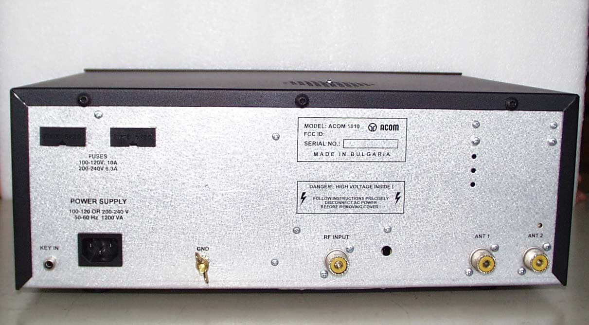
Click to zoom
Application Details
- Equipment Class
- AMP - Amplifier
- Date of Grant
- Apr 19, 2005
- Application Purpose
- Original Equipment
- Date of Application
- Dec 04, 2004
- Equipment Note
- ACOM 1010
- Frequency Range
- 1.80000000 - 21.45000000
- Company
- Acom International Inc
- Country
- United States
Documents & Files
Document Text
Text extracted from the exhibit documents filed with the FCC. Open a document above to read the original.
Users Manual
Exhibit 6 page 1 of 15 International, Inc. Exhibit 6: User’s Manual External Radio Frequency Power Amplifier ACOM 1010 Model 1010 71 West street Medfield, MA 02052 Tel: 508 359 5990 fax: 508 359 5989 E-mail: [email protected] Exhibit 6 page 2 of 15 TABLE OF CONTENTS 1. GENERAL INFORMATION ....................................................................................................................................... 3 1-1. Introduction and Description...................................................................................................................................... 3 1-2. Owner Assistance ......................................................................................................................................................... 3 1-3. Equipment Supplied..................................................................................................................................................... 3 1-4. Features ......................................................................................................................................................................... 3 1-5. Safety Considerations, Explicit Definitions ............................................................................................................... 4 2. INSTALLATION............................................................................................................................................................. 5 2-1. Unpacking and Initial Inspection ............................................................................................................................... 5 2-2. Line Voltage Selection.................................................................................................................................................. 5 2-3. Amplifier Location Selection....................................................................................................................................... 5 2-4. Connections ................................................................................................................................................................... 5 3. POWER ON, CONTROLS AND INDICATORS........................................................................................................ 7 4. OPERATION ................................................................................................................................................................... 9 4-1. Turning ON and OFF .................................................................................................................................................. 9 4-2. Changing Operate and Standby Modes..................................................................................................................... 9 4-3. RTTY Mode ................................................................................................................................................................10 4-4. Antenna change ..........................................................................................................................................................10 4-5. Tuning ..........................................................................................................................................................................10 4-6 The Auto-Protection System ......................................................................................................................................12 5. MAINTENANCE...........................................................................................................................................................12 5-1. Cleaning .......................................................................................................................................................................12 5-2. Fuse Replacement.......................................................................................................................................................13 5-3. Tube Replacement ......................................................................................................................................................13 5-4. Simplified Schematic Diagram .................................................................................................................................13 6. SPECIFICATIONS .......................................................................................................................................................15 6-1. Parameters ..................................................................................................................................................................15 6-2. Functions .....................................................................................................................................................................15 6-3. Storage and Shipment ................................................................................................................................................15 Exhibit 6 page 3 of 15 1. GENERAL INFORMATION Congratulations on purchasing one of the finest HF amplifiers in the world today. Acom is pleased that you have chosen one of our products, and we will endeavor to provide you with the information and support you need to enjoy your purchase for many years. We urge you to read all of the following materials before you embark on operating your new amplifier. 1-1. Introduction and Description This manual explains the installation, operation, and maintenance of the ACOM1010 HF linear amplifier. The ACOM1010 is a self-contained linear amplifier that covers all amateur bands, from 1.8 through 29.7 MHz. It provides over 700-W PEP of output power (or 500 W in continuous-duty operation) with less than 60-W of drive. The amplifier is designed to tolerate VSWR levels of up to 3:1 throughout its operating range, and tuning is simplified by Ac…
Text truncated - open the document above for the full version.
External Photos
Exhibit 2 page 1 of 3 International, Inc. Exhibit 2: External Photos External Radio Frequency Power Amplifier ACOM 1010 Model 1010 71 West street Medfield, MA 02052 Tel: 508 359 5990 fax: 508 359 5989 E-mail: [email protected] Exhibit 2 page 2 of 3 External Photos Fig.1 Front View Exhibit 2 page 3 of 3 Fig.2 Rear View
ID Label/Location Info
Exhibit 1 page 1 of 3 International, Inc. Exhibit 1: ID Label Location Info External Radio Frequency Power Amplifier ACOM 1010 Model 1010 71 West street Medfield, MA 02052 Tel: 508 359 5990 fax: 508 359 5989 E-mail: [email protected] Exhibit 1 page 2 of 3 FCC ID and Label Location Information In compliance with FCC Regulation 47 CFR Ch. 1 part 2.925, the ACOM 1010, External Radio Frequency Power Amplifier, Model 1010 bears a label located on the rear plate of the equipment which displays the following FCC Identifier: Part (a) 1. The term FCC ID followed by the three digit Grantee Code and the six digit Equipment Product Code. 2. Not applicable. 3. Not applicable. Part (b) Not applicable Part (c) Reserved Part (d) 1. The ACOM 1010 label is indelibly printed on the rear panel of the equipment. This label will last the lifetime of the equipment in the environment in which the equipment will be operated and is not readily detachable. 2. The ACOM 1010 label is readily visible on the outside of the equipment enclosure. Part (e) Not applicable. Part (f) 1. The size of the label is 3 by 1.2 inches. The actual label and its location on the equipment are shown in the following pictures. Fig.1 Label location Exhibit 1 page 3 of 3 Fig.2 Actual label In the Serial No., the X’s represent the serialized units in order of manufacture. For example, the first unit will be Serial No. 000001 and the 256th unit will be Serial No. 000256. In the FCC ID # Grantee code is: ... and the ....... portion is the equipment product code.
ID Label/Location Info
Exhibit 1 page 1 of 3 International, Inc. Exhibit 1: ID Label Location Info External Radio Frequency Power Amplifier ACOM 1010 Model 1010 71 West street Medfield, MA 02052 Tel: 508 359 5990 fax: 508 359 5989 E-mail: [email protected] Exhibit 1 page 2 of 3 FCC ID and Label Location Information In compliance with FCC Regulation 47 CFR Ch. 1 part 2.925, the ACOM 1010, External Radio Frequency Power Amplifier, Model 1010 bears a label located on the rear plate of the equipment which displays the following FCC Identifier: Part (a) 1. The term FCC ID followed by the three digit Grantee Code and the six digit Equipment Product Code. 2. Not applicable. 3. Not applicable. Part (b) Not applicable Part (c) Reserved Part (d) 1. The ACOM 1010 label is indelibly printed on the rear panel of the equipment. This label will last the lifetime of the equipment in the environment in which the equipment will be operated and is not readily detachable. 2. The ACOM 1010 label is readily visible on the outside of the equipment enclosure. Part (e) Not applicable. Part (f) 1. The size of the label is 3 by 1.2 inches. The actual label and its location on the equipment are shown in the following pictures. Fig.1 Label location Exhibit 1 page 3 of 3 Fig.2 Actual label In the Serial No., the X’s represent the serialized units in order of manufacture. For example, the first unit will be Serial No. 000001 and the 256th unit will be Serial No. 000256. In the FCC ID # Grantee code is: ... and the ....... portion is the equipment product code.
Internal Photos
Exhibit 7 page 1 of 4 International, Inc. Exhibit 7: Internal Photos External Radio Frequency Power Amplifier ACOM 1010 Model 1010 71 West street Medfield, MA 02052 Tel: 508 359 5990 fax: 508 359 5989 E-mail: [email protected] Exhibit 7 page 2 of 4 Fig.1 Right side View Fig.2 Left side View Exhibit 7 page 3 of 4 Fig.3 Front panel lay down Fig.4 Top-front View Exhibit 7 page 4 of 4 Fig.5 Wattmeter & ant.selection (screen cover removed) Fig.6 Bottom View – Tube Deck (screen cover removed)
Operational Description
Exhibit 8 page 1 of 3 International, Inc. Exhibit 8: Operational Description External Radio Frequency Power Amplifier ACOM 1010 Model 1010 71 West street Medfield, MA 02052 Tel: 508 359 5990 fax: 508 359 5989 E-mail: [email protected] Exhibit 8 page 2 of 3 Operational Description The ACOM1010 is a complete and self-contained linear amplifier that covers the amateur band 1.8-29.7MHz and provides 700W-output power with typically 60W-exciter drive. It is based on and similar to our previous model ACOM1000 (FCC ID: OITA1000) but lower power and without the six meters band. Amplifier’s tuning is simplified by a plate-load True Resistance Indicator (TRI) which helps the operator to quickly and precisely match antennas and eliminates probability of inadvertent mistune. The antenna impedance matching capability is up to VSWR 3:1 or higher. A fixed matching circuit to the tube input is employed which results in a very good load to the exciter over the entire frequency band from 1.8 to 29.7MHz, yielding a good linearity. Look at the schematic diagram (Exhibit 3). The high-performance ceramic-metal tetrode V1, type 4CX800A (GU74B) from SVETLANA, with a plate dissipation of 800W, is grid-driven. The input signal is fed through the fixed input-matching circuit, which comprises several L/C components and a 50 Ohm/100W RF swamping resistor (Rsw) in the INPUT PCB. This circuit tunes out the input capacitance of the tube. The swamping resistor is not an attenuator but it is a termination load for the input matching circuit. It could not be eliminated since a severe impedance mismatch to the driver would prevent using the amplifier at all. The ceramic-composite resistors Rc.1 and Rc.2 create a DC and RF negative feedback in the cathode circuit, thus stabilizing the gain and equalizing the tube specimen performance. The varistor VSsg in the screen grid circuit protects the tube screen grid and the voltage regulator in the events of dynatron effect or a tube internal flashover. The nominal voltages and currents of the tube at rated output power are as follows: DC plate voltage: 2300V for SSB and 2000V for RTTY; DC plate current: 0.48A for SSB and 0.42A for RTTY; DC screen voltage: 265V; DC screen current: 30mA; DC grid bias: -48V (adjusted individually for idling plate current). The combination of Lp1/Rp1 in the plate circuit suppresses possible VHF/UHF parasitic generation. The output resonant circuit comprises the tube output capacitance, Lp1, CP1, CP2, CP3, LP1, LP2, CL1, CL2, CL3, CL4, and LL, all connected in a double-Pi-L network. It transforms the antenna impedance to the tube-optimum load impedance, and besides suppresses the harmonic frequency emissions. The tank is tuned over the bands and the impedance matching is controlled by the ceramic-supported air variable capacitors CP1, CP2, CL1, and CL2. The DC plate voltage is fed through the plate-choke RFC1 to the anode, in a parallel circuit with the tank. The series capacitors Cb3.1 and Cb3.2 prevent the DC voltage from reaching the resonant tank and/or amplifier’s output, while the low-pass filter Cb1.1/Cb1.2/RFC2/Cb2 prevents the RF voltage from reaching the DC power source. The output signal is fed through a piece of coaxial cable, to the “RF OUTPUT” connector through the wattmeter. A high-pass filter at the output (integrated with the wattmeter) eliminates the influence of eventual close-sited powerful LF/MF transmitters as well as 50/60Hz power lines on the amplifier. Also, it prevents DC high voltage from reaching the antenna output, thus improving operator’s safety. The amplifier is controlled by a microprocessor system, based on the ATmega micro- controller from Atmel. It uses a 4MHz clock, stabilized by a piezo-ceramic resonator. An intended constructive capacitance Ca feeds information from the plate RF voltage. Together with the directional RF wattmeter at the output, they are the main information sources for the control circuit to form the TRI aid during the antenna impedance matching process. The relay K1 0n the wattmeter PCB switches the antenna for transmit and receive. The relay K2 on the same PCB selects two different antenna outputs A1 and A2. Exhibit 8 page 3 of 3 All supply voltages are delivered from conventional rectifiers and linear regulators and no switching supplies are used. The currents of the tube control grid, screen grid, and plate, as well as the forward and reflected power, the alternative anode voltage etc are continuously monitored by the uP controller. Many software-derived protections are based on this information in order to insure normal tube regime and antenna tuning, thus drastically reducing the probability of any inadvertent operator’s mistakes or apparatus irregularities that could arise during exploitation of the amplifier.
Parts List/Tune Up Info
Exhibit 11 Page 1 of 13 International, Inc. Exhibit 11: Tuning Procedure and Parts List External Radio Frequency Power Amplifier ACOM 1010 Model 1010 71 West street Medfield, MA 02052 Tel: 508 359 5990 fax: 508 359 5989 E-mail: [email protected] Exhibit 11 Page 2 of 13 4-5. Tuning Tuning is possible only in the OPER mode. a) Preliminary information. Tuning the amplifier involves a procedure of matching the impedance of the antenna and transmission line to the amplifier tube’s characteristic load resistance. This will ensure maximum plate efficiency and RF gain at nominal output power, with minimal distortion and spurious output. Note that REFLECTED POWER readings depend on the antenna and transmission line impedances only, and not on amplifier tuning. If the load impedance is not a nominally resistive 50-Ohms, the REFLECTED POWER reading will always show a reading, no matter what the tuning settings. Proper tuning is always necessary, however, and will allow you to operate at a high power level, without distortion or any danger to the amplifier. Note also that the real OUTPUT POWER presented to the load (the antenna and transmission line) is equal to the difference between the FORWARD and REFLECTED power readings. For instance, with a 2.5:1 VSWR, readings of 800 W and 150 W FORWARD POWER and REFLECTED POWER, respectively, the real OUTPUT POWER is 650 W. At very high VSWR levels, such as when no antenna is connected or a badly mismatched antenna is used, the FORWARD and REFLECTED readings will be almost equal, while the real OUTPUT POWER (the difference between them) will be nearly zero. The amplifier can operate safely as long as the REFLECTED POWER is LESS THAN 250 W. Matching is assured for loads presenting a VSWR of up to 3:1. Nevertheless, for some loads and bands, matching is possible at even higher VSWR levels, but the drive power must be reduced to prevent the REFLECTED POWER from exceeding 250W. Failure to comply with these guidelines will cause the protection circuits to trip. For example, if the antenna VSWR were 5:1, the maximum attainable forward power would be 540 W, 240 W of reflected power and real output to the antenna and transmission line of only 300 W. In the event your antenna cannot be adjusted to produce a lower VSWR, an external antenna tuner may be deployed. CAUTION At elevated VSWR levels, high voltages and high currents are distributed along the coaxial cable to the antenna, risking internal arcing and heat generation, and likely damage to the cable and any antenna switches that may be used. It is recommended that VSWR levels of more than 3:1 not be permitted with coaxial cable above 14 MHz. It is advisable to adjust amplifier tuning when antennas have been changed, snow has fallen, new objects are in the near field of the antenna, etc. Such changes may affect antenna impedance. NOTE If you use more than one antenna on a band, the proper antenna must be selected prior to performing the tuning procedure outlined below. CAUTION To avoid damage not covered under warranty, do not switch the BAND switch knob while transmitting. As discussed above, hot switching will damage the amplifier’s band switch! CAUTION Also, never apply drive longer than one minute continuously without pausing for at least one minute to allow the tube to cool. It is recommended that for initial tuning a frequency in the middle of the band be used. First, with no transceiver power applied, select the band. Then use Table 4-1 to achieve an approximate preset for both TUNE and LOAD capacitor knob settings: Exhibit 11 Page 3 of 13 Band LOAD TUNE MHz Knob Dial Knob Dial 1.800 - 2.000 42 - 71 55 - 28 3.500 - 4.000 32 - 57 52 - 31 7.000 - 7.300 29 - 40 36 - 27 10.100 - 10.150 59 - 66 50 - 44 14.000 - 14.350 33 - 39 42 - 30 18.068 - 18.168 17 - 35 60 - 50 21.000 - 21.450 50 - 60 15 - 10 24.890 - 24.990 38 - 42 80 - 72 28.000 - 29.700 51 - 64 41 - 24 Table 4-1. Approximate tuning preset b) Tuning Procedure. (1) Once the antenna and band have been selected (and the TUNE and LOAD adjustments have been initially set as indicated in Table 4-1), apply between 10 and 20 W of continuous (key down CW) signal. (2) Look at the upper LED bar-graph (FORWARD POWER) and adjust the TUNE (right hand) capacitor for maximum indication. (3) Watch the TRI indicator above the LOAD (left hand) capacitor and turn the LOAD capacitor in the indicated direction to center the green LED indicator light. (4) Increase the drive power to get the desired nominal output; then repeat steps (2) and (3), always peaking output with the TUNE adjustment. NOTE No light on the TRI indicator means that the tuning is too far off. To correct this, turn the LOAD and TUNE knobs around the table-suggested positions until the TRI indicator illuminates. no light: tuning is far left: tuning is far right: marker inside: LOAD is tuned: use TUNE knob turn LOAD knob turn LOAD knob turn LOAD knob turn TUNE knob for max. Power to the right to get to the left to get slightly left to peak Forward to get any marker the inside markers inside markers to center it Power Fig. 4-1. Using TRI tuning aid The TRI indicator will not illuminate until at least 20 W of forward power (output) is achieved. In the event successful matching cannot be accomplished, check the BAND switch position and antenna selection. Then check the antenna VSWR at the same drive frequency. d) Tuning hint. A benefit of TRI is that the knob positions are virtually independent. The plate-load resistance decreases to the right and increases to the left of the TRI center. A centered tuning indication corresponds to the proper LOAD capacitor tuning, which presents an optimum load resistance to the tube. If the LOAD knob is turned to the left with a centered TRI, there will be more gain, but less linearity. When available drive power is insufficient or when less output but better efficiency are needed, e.g., for RTTY and SSTV, this may be desirable. Tuning to the right of the center would lead to the op…
Text truncated - open the document above for the full version.
Schematics
Exhibit 4 page 1 of 14 International, Inc. Exhibit 4: Schematics External Radio Frequency Power Amplifier ACOM 1010 Model 1010 71 West street Medfield, MA 02052 Tel: 508 359 5990 fax: 508 359 5989 Exhibit 4 page 2 of 14 Exhibit 4 page 3 of 14 Exhibit 4 page 4 of 14 Exhibit 4 page 5 of 14 Exhibit 4 page 6 of 14 Exhibit 4 page 7 of 14 Exhibit 4 page 8 of 14 Exhibit 4 page 9 of 14 Exhibit 4 page 10 of 14 Exhibit 4 page 11 of 14 Exhibit 4 page 12 of 14 Exhibit 4 page 13 of 14 Cable Harness Connections: CONTROL JP1 Signal name To: 1 +5V MAINS JP1:1 2 GND MAINS JP1:2 3 g1warn MAINS JP1:3 4 g2warn MAINS JP1:4 5 *KEYIN Rear panel - KEYIN 6 ipg2 MAINS JP1:6 7 G1VL MAINS JP1:7 8 ENAB MAINS JP1:8 9 RTTY MAINS JP1:9 10 *STST MAINS JP1:10 11 GND Rear panel - KEYIN 12 +15V MAINS JP1:12 CONTROL JP2 Signal name To: 1 fwdi WATTMETER JP1:1 2 rfli WATTMETER JP1:2 3 *ORCW WATTMETER JP1:3 4 GND WATTMETER JP1:4 5 *OUTR WATTMETER JP1:5 6 aavd WATTMETER JP1:6 7 GND INPUT JP1:6 8 *INR INPUT JP1:2 9 GND - 10 *ANT2 WATTMETER JP1:10 MAINS JP1 Signal name To: 1 +5V CONTROL JP1:1 2 GND CONTROL JP1:2 3 g1warn CONTROL JP1:3 4 g2warn CONTROL JP1:4 5 GND - 6 ipg2 CONTROL JP1:6 7 G1VL CONTROL JP1:7 8 ENAB CONTROL JP1:8 9 RTTY CONTROL JP1:9 10 *STST CONTROL JP1:10 11 GND - 12 +15V CONTROL JP1:12 MAINS JP2 Signal name To: 1 +15V INPUT JP1:5 2 GND INPUT JP1:3 3 BIAS INPUT JP1:8 4 n/c - 5 +265V INPUT JP1:10 INPUT JP1 Signal name To: 1 aavi WATTMETER JP1:7 2 *INR (CONTROL JP2:8) 3 GND (MAINS JP2:2) Exhibit 4 page 14 of 14 Cable Harness Connections (continued): 4 +15V WATTMETER JP1:8 5 +15V (MAINS JP2:1 6 GND (CONTROL JP2:7) 7 GND WATTMETER JP1:9 8 BIAS (MAINS JP2:3) 9 n/c - 10 +265V (MAINS JP2:5) WATTM. JP1 Signal name To: 1 fwdi (CONTROL JP2:1) 2 rfli (CONTROL JP2:2) 3 *ORCW (CONTROL JP2:3) 4 GND (CONTROL JP2:4) 5 *OUTR (CONTROL JP2:5) 6 aavd (CONTROL JP2:6) 7 aavi (INPUT JP1:1) 8 +15V (INPUT JP1:4) 9 GND (INPUT JP1:7) 10 *ANT2 (CONTROL JP2:10) End
Test Report
Exhibit 5 page 1 of 6 International, Inc. Exhibit 5: EMI Test Report External Radio Frequency Power Amplifier ACOM 1010 Model 1010 71 West street Medfield, MA 02052 Tel: 508 359 5990 fax: 508 359 5989 E-mail: [email protected] Exhibit 5 page 2 of 6 EMI Test Report for ACOM International, inc. Product Name: ACOM1010 Regulation: FCC, Part97 Sub Part D Date of test: APR 15 2004 Tested by: Eng. Dr. Stanimir Lekov, R&D at ACOM OOD Test Method: FCC, Part 97.317 (a)(1)(2)(3), (b)(1)(2), (c)(i)(ii) Part 97.307 (d), (e) Responsible Parties Manufacturer: ACOM OOD – Bulgaria Applicant: ACOM International Inc. USA EUT Type/Model #: Linear Amplifier ACOM1010 Test Location: ACOM OOD laboratory EUT Description The EUT (ACOM1010) is a Linear Amplifier for Amateur Radio. The tests were run in a typical configuration including the following support equipment: 1) H.F. plus six meters Transceiver 2) Power Supply for transceiver Reason for Test Qualification for FCC Part 97 Changes made during test: none Deviations from standard test method: none Test Summary The ACOM1010 complied with FCC Part 97 Subpart D, 97.307 and 97.317 Limits for Amateur Radio equipment when tested in the system configuration defined herein. The following table indicates the measurement points and test results for the harmonic emissions to the tenth order: Exhibit 5 page 3 of 6 Power Gain per 97.317-(a) (1) (2) (3), (c) (6) (ii) Spurious emissions per 97.307 (e) Frequency f 1 , MHz Input Power, W Output Power, W Amplifier Gain, dB 2f1, dBc 3f1, dBc 4f1, dBc 5-10f1, dBc worst case 1.900 53.1 700 11.2 -53.5 -79,5 -84,5 -72.7 3.750 61.0 700 10.6 -53.0 -98.1 -87.0 -93,6 7.150 73.3 700 9.8 -58.5 -99.9 -97.5 -94.5 10.125 62.4 700 10.5 -53.8 -95.5 -67.3 -95.0 14.175 60.9 700 10,6 -57.5 -96.7 -89.1 -84.6 18.100 65.3 700 10.3 -53.2 -77.6 -78.5 -74.8 21.225 58.2 700 10.8 -61.6 -90.2 -84.6 -77.0 Amplifier was not capable of operation on any frequency or frequencies between 24 and 35MHz as measured at the points below per 97.317-(b) (1) (2). Data for: amplifier in Stand-by / amplifier ON. 24.000 50 49.1 / 169 -0.1 / 5.3 26.000 50 48.3 / 47.8 -0.15 / -0.2 27.120 50 48.3 / 34.6 -0.15 / -1.6 28.000 50 48.3 / 28.1 -0.15 / -2.5 35.000 50 47.9 / 1.17 -0.2 / -16.3 Amplifier was not capable of full power output and the gain is less than 11.3dB when driven with less than 50 watts per 97.317-(c)(6) (i)(iii). 1.900 30 405 11.3 3.750 30 353 10.7 7.150 30 307 10.1 10.125 30 344 10.6 14.175 30 352 10.7 18.100 30 345 10.6 21.225 30 369 10.9 24.930* 30 322 10.3 28.500* 30 352 10.7 After owner modification to activate 24-28 MHz bands: 24.930* 71.6 700 9.9 -73.7 -82.4 -81.0 -61.1 28.500* 60.1 700 10.7 -67.5 -82.8 -82.2 -70.5 *Not usable as shipped; data applicable only after enabling of 24.5 & 28 MHz bands as follows. Exhibit 5 page 4 of 6 The following table indicates the measurement points and test results for the Inter Modulation Distortions to the 11-th order: Inter-modulation in dB relative to 700W PEP per 97.307(a)(b) Order: D3 D5 D7 D9 D11 and higher Freq. (MHz) dB dB dB dB dB 1.900 -45 -48 -44 -50 -53 3.750 -43 -49 -45 -47 -52 7.150 -42 -47 -45 -47 -51 10.125 -46 -46 -45 -51 -53 14.175 -44 -46 -47 -52 -59 18.100 -40 -46 -50 -54 -57 21.225 -42 -46 -48 -54 -56 24.930* -45 -45 -49 -54 -58 28.500* -38 -40 -44 -52 -56 *Not usable as shipped; data applicable only after authorized owner modification. Fig.1 Setup Block Diagram for ACOM1010 Exhibit 5 page 5 of 6 EUT Technical Data Description: Linear Amplifier ACOM1010 Manuf/Model: ACOM OOD Bulgaria / Model 1010 Serial #: 000001 FCC/FTZ Ident.: N/A Power (Rated): 240 VAC 50/60Hz Power (Tested): 240VAC 50Hz Internal Options: None Frequencies Amplified: Amateur radio bands from 1.8MHz through 29.7MHz Support Equipment Data Description: HF Transceiver Manuf/Model: ICOM Model No. IC-746 Serial #: 03678 Power: 220VAC 50Hz Internal Options: None Frequencies Generated: from 1.8MHz through 35MHz Description: Two-Tone Generator Manuf/Model: Kenwood Station Monitor, Model SM-220 Serial #: None Power: 220VAC 50Hz Internal Options: None Frequencies Generated: 1000Hz plus 1575Hz Audio Description: Laboratory Auto-Transformer Manuf/Model: RFT, Model LSS 020 Serial #: 13/004 Power: 220VAC 50Hz Internal Options: None Frequencies Generated: None Cables Description Transceiver Ant. to Input Power Meter - RG58/U, 1m length Input Power Meter to EUT input - RG58/U, 25cm length Output Power Meter to Dummy/Attenuator - RG213/U, 1m length Dummy/Atten/out to Spectrum Analyzer - RG58/U, 1.5m length Exhibit 5 page 6 of 6 EUT I/O Ports ACOM1010 Key-In (Transmit/Receive Relay Control) RF INPUT 50 Ohm RF OUTPUT A1 or A2 - 50 Ohm Mains AC Input 240V 50/60Hz Test Equipment List # Equipment type Manufacturer Model # Serial # Used 1 Spectrum Analyzer TEKTRONIX 2710 B 02 0771 Yes 2 Spectrum Analyzer Russia CK4-59 8806264/8806204 Yes 3 2kW 60dB Attenuator ACOM IM-400 004 Yes 4 20dB Attenuator Russia n/a n/a Yes 5 Signal Generator Marconi Instruments MI 2018A 118454/058 Yes 6 Power Meter Bird Electronic Corp. Model 4421-101 1665 Yes 7 Power Sensor Bird Electronic Corp. 4021 0004 Yes 8 Power Sensor Bird Electronic Corp. BIR 100A n/a Yes 9 HF plus 6m Transceiver ICOM IC-746 03678 Yes 10 Two-Tone Generator Kenwood SM-220 Station Monitor n/a Yes 11 Laboratory Auto- Transformer RFT LSS 020 13/004 Yes
Test Report
Exhibit 9 page 1 of 4 International, Inc. Exhibit 9: Additional Information in Response to 47 CFR Ch.1 Sec. 2.1033 External Radio Frequency Power Amplifier ACOM 1010 Model 1010 71 West street Medfield, MA 02052 Tel: 508 359 5990 fax: 508 359 5989 E-mail: [email protected] Exhibit 9 page 2 of 4 Additional Information in Response to 47 CFR Ch.1 Sec. 2.1033 Section c.1. The "ACOM1010” HF linear amplifier will be assembled and production testing performed in the Republic of Bulgaria by the private company “ACOM, OOD”. ACOM, OOD has been designed and manufactured external radio frequency power amplifiers for amateur use since 1990. The company has designed and manufactured the following types of amplifiers: - the "ETO 91B" HF Linear Amplifier accepted as FCC ID: DGVPA-91B which was marketed in the United States by Alpha/Power, Inc. of Colorado Springs, COLORADO continuously till 1999; - the "ACOM2000A” Automatic HF Linear Amplifier accepted as FCC ID: OITAA2000, which is in volume production and is being presently marketed in the United States by the Applicant; - the “ACOM1000” HF+6m Linear Amplifier accepted as FCC ID: OITAA1000, which is in volume production and is being presently marketed in the United States by the Applicant. ACOM, OOD is located at Bul.Gornobanski Nr.151, 1330 Sofia Bulgaria. The president and principal owner of ACOM, OOD is Mr. Vassil M. Vassilev. Applicant for certification, ACOM International, Inc. is the exclusive distributor of ACOM, OOD products in North America. With respect to the subject, "ACOM1010” HF linear amplifier equipment, Applicant is responsible for all aspects of quality assurance, marketing and service in USA, as well as for the compliance with FCC rules. ACOM International, Inc. is located at 71 West street Medfield, MA 02052, USA. Applicant has conducted or observed all design-proof testing and will re-test samples of production equipment on an ongoing basis to assure conformance to Applicant's quality standards, including all FCC regulatory requirements. Section c.2 This product designated "ACOM1010 HF linear …
Text truncated - open the document above for the full version.
Contact Information
Applicant
Krassimir Dikov Petkov(President)
Test Firm
Test Site Services Co.Lawrence Lee
Technical Specifications
| # | Rule Parts | Frequency Range | Power Output | Emission | Tolerance |
|---|---|---|---|---|---|
| 1 | 97 | 1.8 MHz - 21.45 MHz | 700 W | XXX | Amp |