SS3-2013090012.4G Bluetooth Data link
SZ DJI TECHNOLOGY CO., LTD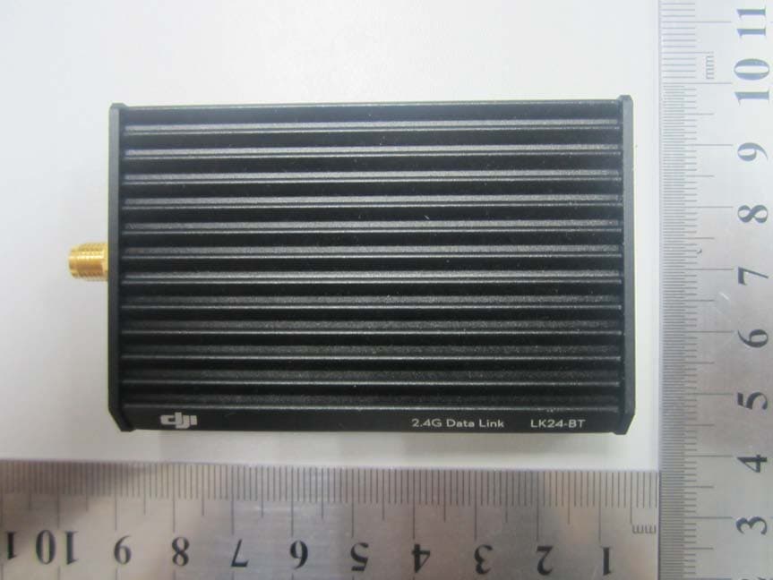
Click to zoom
Application Details
- Equipment Class
- DTS - Digital Transmission System
- Date of Grant
- Nov 05, 2013
- Application Purpose
- Original Equipment
- Date of Application
- Nov 05, 2013
- Equipment Note
- 2.4G Bluetooth Data link
- Frequency Range
- 2405.37600000 - 2477.05600000
- Company
- SZ DJI TECHNOLOGY CO., LTD
- Country
- China
Documents & Files
Document Text
Text extracted from the exhibit documents filed with the FCC. Open a document above to read the original.
Users Manual
©2013 DJI Innovations. All Rights Reserved. - 1 - Thank you for purchasing DJI products. Please strictly follow this user guide to mount and connect the 2.4G Bluetooth Datalink, install the Assistant Software on your computer, as well as the App on your mobile device. Note:The map of Mainland China download from Mainland China IP addresses has differences with the actual geographic environments. If users download the map of Mainland China from foreign IP addresses, which will be more accurate. 2.4G Bluetooth Datalink The 2.4G Bluetooth Datalink consists of the Air end and the Ground end, which provides reliable and stable remote wireless transmissions for Ground Station based applications. When connecting a DJI BTU module to the Ground end via a CAN-Bus, the Ground end can communicate with other devices via Bluetooth wirelessly. The signal flow is as shown below. The Air end The Air end The Ground end The Ground end Flight control system Flight control system PC Ground Station PC Ground Station iPAD Ground Station iPAD Ground Station CAN-Bus CAN-Bus USB USB Signals from Ground Station Signals from Flight control system BTU Module BTU Module Bluetooth Bluetooth CAN-Bus CAN-Bus Flight control systems that support the 2.4G Bluetooth Datalink ACE ONE(Firmware V4.02 or above), WKM(Firmware V5.24 or above), NAZA-M, NAZA-M V2(Firmware V4.00 or above,coming soon) 1.1 In the box BTU Module USB cable CAN-Bus cable DC power cable Ground Station Installer CD for PC The Ground end of 2.4G Bluetooth Datalink The Ground end of 2.4G Bluetooth Datalink The Air end of 2.4G Bluetooth Datalink Important:the firmware of BTU should be upgraded to version 1.0.1.2 or above to use with the 2.4G Bluetooth Datalink. 1.2 User supplied To use the 2.4G Bluetooth Datalink and Ground Station, please prepare the Flight control system, the aircraft, batteries, PC or iPAD etc. 1.3 Connections and use (1) Please assemble the antenna of the Ground end first. 2.4G Bluetooth Datalink LK24-BT ©2013 DJI Innovations. All Rights Reserved. - 2 - (2) For connections and use please refer to the diagram below. Antenna The tail of the Antenna should be pointed downward and unobstructed to ensure the communication distance. · PC Ground Station · 2.4G Bluetooth Datalink Assistant Software · Assistant Software of Flight control system USB port Connect to a PC via a USB cable to use the PC Ground Station or configure the 2.4G Bluetooth Datalink in the Assistant Software. CAN-Bus port Connect the BTU module when using the iPAD Ground Station DC power port Connect DC power, you can choose one of the USB power supply or DC power supply to provide power for the Ground end. The Ground end Distance between the two ends should be more than 1.5m Communication& power supply port Extra power supply port · 3S-6S Battery · 9.9V~25.2V DC power - + · iPAD Ground Station · Assistant of Flight control system + - 90 o To Flight control system To any CAN-Bus port on ACE ONE, WKM , NAZA-M, NAZA-M V2 The Air end Antenna The tail of the Antenna should be pointed upwards and unobstructed to ensure the communication distance. Notes: (1) You can configure the Flight control system using the Assistant software on a PC or iOS mobile Device wirelessly over the link of the 2.4G Bluetooth Datalink, however you cannot upgrade the firmware of the Flight control system using this communication route. (2) When connecting a BTU module or a LED Bluetooth unit to the Flight control system to configure in the Assistant on mobile devices, as well as connecting a BTU module to the Ground end to use the iPAD Ground station, the two Bluetooth communication links will not interfere with each other. (3) If the Air end is changed to connect to a new Main controller, you should power cycle the Ground end. (4) Make sure the LED indicator of BTU module is green after power on, for specific usage details please refer to the BTU Manual. (5) For usage of the PC Ground Station please refer to the latest Ground Station User Manual. Important : (1) If there are obstacles between the ground and air ends then the radio signal of the 2.4G Bluetooth Datalink will be weak; please make sure the antennas are always visibly unobstructed during the flight. Human body, trees, buildings or hills will disconnect the link between the Air end and the Ground end. (2) Make sure the antenna of the Air end is pointing down, and the antenna of the Ground end is pointing upwards; it’s better to put the Ground end at a high place to get further transmission distance. (3) When using the ACE ONE Flight control system with the 2.4G Bluetooth Datalink, the Ground Station will connect to the Main controller 15s after power on. ©2013 DJI Innovations. All Rights Reserved. - 3 - 1.4 LED Indicator descriptions The LED Indicators of the 2.4G Bluetooth Datalink will work after power on, the descriptions are shown below. LED TX/RX LINK The Air end LINK TX/RX Green blinks Sending Solid Green The Air end links with the Ground end successfully Red blinks Receiving Solid Red The Air end delinks with the Ground end Yellow blinks Searching the Main controller The Ground end TX/RX LINK Green blinks Sending Solid Green The Air end links with the Ground end successfully Red blinks Receiving Solid Red The Air end delinks with the Ground end Yellow blinks Power voltage of the Ground end is less than 9.9V Notes : (1) LED Indicators on both ends will blink when powering on, then the TX/RX indicator of the Air end will blink when searching the Main controller. (2) The LED Indicators of LINK on both ends should be solid green to indicate that the two ends have linked successfully. (3) It’s recommended to check the power voltage of the Ground end regularly when using batteries for power supply, in order to avoid over-discharging. 1.5 Upgrade Use the 2.4G Bluetooth Datalink Assistant software to upgrade the 2.4G Bluetooth Datalink and BTU module. Please refer to the diagram below to connect when upgrading. ·2.4G Bluetooth Datalink Assistan…
Text truncated - open the document above for the full version.
Cover Letter(s)
Date: 2013-10-31 To : Federal Communications Commission, Authorization & Evaluation Division, 7435 Oakland Mills Road, Columbia, MD 21046 To Whom It May Concern: The SZ DJI TECHNOLOGY CO.,LTD , the undersigned, hereby authorizes Ms. Ivy Zhu from Shenzhen Morlab Communications Technology Co., Ltd., to act on the behalf of the SZ DJI TECHNOLOGY CO.,LTD solely in matters relating to the application for an FCC equipment authorization for FCC ID SS3-201309001 including the signing of documents in connection with this Application. Necessary acts carried out by SZ DJI TECHNOLOGY CO.,LTD on our behalf of the SZ DJI TECHNOLOGY CO.,LTD in connection with the Application shall have the same effect as acts of the SZ DJI TECHNOLOGY CO.,LTD. The SZ DJI TECHNOLOGY CO.,LTD also hereby certify that no party to this application is subject to a denial of benefits, including FCC benefits, pursuant to Section 5301 of the Anti-Drug Abuse Act of 1988, 21 U.S.C. 853(a). Thank you for your attention to this matter. Yours Sincerely, Yongqian Fan manager
External Photos
External Photos 1. EUT full view with accessories 2. The Ground end front view 3. The Ground end rear view 4. The Ground end left side view 5. The Ground end right side view 6. The Ground end top view 7. The Ground end bottom view
ID Label/Location Info
FCC label and label location 1. Label Size:73mm*47.8mm 2.label location Location:
Internal Photos
In ternal Photos-The Ground end 1. EUT uncover view 2. Mainboard front view with shielding 3. Mainboard front view without shielding 4. Mainboard rear view 5. RF chip view 6. Antenna view
Test Report
SZ13080123W04 Page 2 of 39 DIRECTORY 1. GENERAL INFORMATION .................................................................................................... 3 1.1. EUT Description ....................................................................................................................... 3 1.2. Test Standards and Results ........................................................................................................ 4 1.3. Facilities and Accreditations ..................................................................................................... 5 2. 47 CFR PART 15C REQUIREMENTS .................................................................................... 6 2.1. Antenna requirement ................................................................................................................. 6 2.2. Number of Hopping Frequency ................................................................................................ 6 2.3. Peak Output Power.................................................................................................................... 8 2.4. 20dB Bandwidth ..................................................................................................................... 10 2.5. Carried Frequency Separation ................................................................................................. 13 2.6. Time of Occupancy (Dwell time) ........................................................................................... 15 2.7. Conducted Spurious Emissions ............................................................................................... 17 2.8. Restricted Frequency Bands.................................................................................................... 22 2.9. Conducted Emission ............................................................................................................... 26 2.10. Radiated Emission................................................................................................................... 29 2.11. RF exposure evaluation ........................................................................................................... 38 Change History Issue Date Reason for change 1.0 October 30, 2013 First edition SZ13080123W04 Page 3 of 39 1. General Information 1.1. EUT Description EUT Type ............................. : 2.4G Bluetooth Datalink Serial No. .............................. : (n.a, marked #1 by test site) Hardware Version ................. : V1 Software Version .................. : Applicant .............................. : Manufacturer ........................ : 1.0 SZ DJI TECHNOLOGY CO.,LTD Room 613、614, 6/F, HKUST SZ IER Bldg, No.9 Yuexing 1st Rd Hi-Tech Park(South), Nanshan District, Shenzhen, Guangdong, China SZ DJI TECHNOLOGY CO.,LTD 6F, HKUST SZ IER Bldg. No.9 Yuexing 1st Rd. Hi-Tech Park(South), Nanshan Dist. Shenzhen, Guangdong, China Frequency Range .................. : The frequency range used is 2405.376MHz – 2477.056MHz (36channels, at intervals of 2.048MHz); The frequency block is 2400MHz to 2483.5MHz. Modulation Type .................. : FHSS Antenna Type ........................ : SMA Antenna Antenna Gain ........................ : 1.8dBi Note 1: The EUT is 2.4G Bluetooth Datalink, it operating at 2.4GHz ISM band, the frequencies allocated is F (MHz) =2405.376+2.048*(n-1) (1<=n<=36). The lowest, middle, highest channel numbers of the EUT used and tested in this report are separately 1 (2405.376MHz), 18 (2440.192MHz) and 36 (2477.056MHz). Note 2: For a more detailed description, please refer to Specification or User’s Manual supplied by the applicant and/or manufacturer. SZ13080123W04 Page 4 of 39 1.2. Test Standards and Results The objective of the report is to perform testing according to 47 CFR Part 15 Subpart C for the EUT FCC ID Certification: No. Identity Document Title 1 47 CFR Part 15 (10-1-12 Edition) Radio Frequency Devices Test detailed items/section required by FCC rules and results are as below: No. Section in CFR 47Description Result 1 15.203 Antenna Requirement PASS 2 15.247(a) Number of Hopping Frequency PASS 3 15.247(b) Peak Output Power PASS 4 15.247(a) 20dB Bandwidth PASS 5 15.247(a) Carrier Frequency Separation PASS 6 15.247(a) Time of Occupancy (Dwell time) PASS 7 15.247(d) Conducted Spurious Emission PASS 8 15.247(d) Restricted Frequency Bands PASS 9 15.207 Conducted Emission PASS 10 15.209 15.247(d) Radiated Emission PASS 11 15.247(i), 1.1307&2.1093 RF exposure evaluation PA S S NOTE: The tests were performed according to the method of measurements prescribed in DA-00-705. SZ13080123W04 Page 5 of 39 1.3. Facilities and Accreditations 1.3.1. Facilities Shenzhen Morlab Communications Technology Co., Ltd. Morlab Laboratory is a testing organization accredited by China National Accreditation Service for Conformity Assessment (CNAS) according to ISO/IEC 17025. The accreditation certificate number is L3572. All measurement facilities used to collect the measurement data are located at FL.1, Building A, FeiYang Science Park,Block 67, BaoAn District, Shenzhen, 518101 P. R. China. The test site is constructed in conformance with the requirements of ANSI C63.10 2009, ANSI C63.4 2009 and CISPR Publication 22; the FCC registration number is 695796. 1.3.2. Test Environment Conditions During the measurement, the environmental conditions were within the listed ranges: Temperature (°C): 15 - 35 Relative Humidity (%): 30 -60 Atmospheric Pressure (kPa): 86-106 SZ13080123W04 Page 6 of 39 2. 47 CFR Part 15C Requirements 2.1. Antenna requirement 2.1.1. Applicable Standard According to FCC 15.203, an intentional radiator shall be designed to ensure that no antenna other than that furnished by the responsible party shall be used with the device. The use of a permanently attached antenna or of an antenna that uses a unique coupling to the intentional radiator shall be considered sufficient to comply with the provisions of…
Text truncated - open the document above for the full version.
Test Setup Photos
Test Setup Photos 1. Conducted emission main’s port front view 2. Conducted emission main’s port side view 3. Radiated emission (9KHz-30MHz) 4. Radiated emission (30MHz-1GHz) 5. Conducted emission antenna’s port
Contact Information
Applicant
Gary Zeng(PM)
Technical Contact
Shenzhen Morlab Communications Technology Co.,LtdIvy Zhu
[email protected]86-755-36698618
FL.3, Building A, FeiYang Science Park · ShenZhen, GuangDong Province · China
Test Firm
Shenzhen Morlab Communications Technology Co., LtdIvy zhu
Technical Specifications
| # | Rule Parts | Frequency Range | Power Output |
|---|---|---|---|
| 1 | 15C | 2.41 GHz - 2.48 GHz | 110.00 mW |
Other Applications from SZ DJI TECHNOLOGY CO., LTD
SS3-T55A2510
Dec 19, 2025DJI AGRAS T55
Equipment Class
NII - Unlicensed National Information Infrastructure TXSS3-T100A2510
Dec 19, 2025DJI AGRAS T100S, DJI AGRAS T70S
Equipment Class
NII - Unlicensed National Information Infrastructure TXSS3-TKMI2507
Dec 19, 2025DJI RC Mini
Equipment Class
DTS - Digital Transmission SystemSS3-RD60B2510
Dec 18, 2025Fixed Millimeter Wave Radar
Equipment Class
FDS - Part 15 Field Disturbance SensorSS3-RD60A2510
Dec 18, 2025Rotational Active Phased Array Radar
Equipment Class
FDS - Part 15 Field Disturbance Sensor