SS3-GL658C1504C1
SZ DJI TECHNOLOGY CO., LTD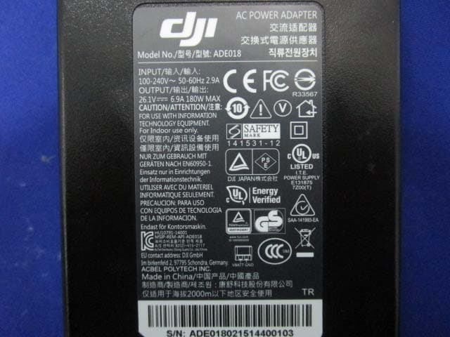
Click to zoom
Application Details
- Equipment Class
- DTS - Digital Transmission System
- Date of Grant
- Jun 04, 2015
- Application Purpose
- Original Equipment
- Date of Application
- Jun 04, 2015
- Equipment Note
- C1
- Frequency Range
- 2404.00000000 - 2480.00000000
- Company
- SZ DJI TECHNOLOGY CO., LTD
- Country
- China
Documents & Files
Document Text
Text extracted from the exhibit documents filed with the FCC. Open a document above to read the original.
Users Manual
©2015 DJI. All Rights Reserved. 1 DJI Matrix 100 User Manual V 1.0 2015.5 www.dji.com ©2015 DJI. All Rights Reserved. 2 Using this manual Legend Warning Important Hints and Tips Reference Before Flight The following tutorials and manuals have been produced to ensure you to make full use of your M100. 1. Safety Guidelines and Disclaimer 2. M100 User Manual 3. In the Box 4. Intelligent Flight Battery Safety Guidelines Reading the Safety Guidelines and Disclaimer before flight is recommended. Refer to this manual for more comprehensive information. Download the DJI Pilot app Download and install the DJI Pilot app before use. Scan the QR code or visit “http://m.dji.net/djipilot” to download the app. For the best experience, use mobile device with Android V 4.1.2 or above. Requires iOS 8.0 or later. ©2015 DJI. All Rights Reserved. 3 Warnings When flying, the rotating propellers may cause serious damage and injury. Please fly safely at all times. Assembly Warnings (1) Ensure that all parts are installed before inserting the Intelligent Flight Battery. (2) Use a bracket to mount the GPS module onto the center frame to avoid interference with the power board. (3) Ensure frame arms are mounted correctly. (4) Do not remove any glued-in screws. (5) Screws that already have blue glue can be used once without thread locker. On other occasions, apply appropriate thread locker first. Flight Warnings (1) ESCs are not waterproof, please do not fly in rain or snow. (2) Ensure all parts are in good condition before each flight. Do not fly with worn or broken parts. (3) Ensure propellers and motors are installed correctly before flying. (4) Ensure all cables are secure before every flight. (5) When flying, maintain a safe distance away from people, buildings, high voltage power lines, tall trees, water and other hazards. (6) Use only DJI TB47D/TB48D Intelligent Flight Batteries as the power supply. (7) Do not overload the system. (8) Do not get close to or touch motors or propellers when they are spinning, as this can cause serious injury. (9) Disconnect the battery and remove the camera during transportation to avoid damage or injury. (10) Only use compatible DJI parts. If you encounter any problems or if you have any questions, please contact your local DJI authorized dealer or DJI Support. DJI Support Website: www.dji.com/support ©2015 DJI. All Rights Reserved. 4 Contents Using this manual ......................................................................................................................................................................................................... 2 Legend .................................................................................................................................................................................................................... 2 Before Flight ........................................................................................................................................................................................................ 2 Download the DJI Pilot app .......................................................................................................................................................................... 2 Warnings .......................................................................................................................................................................................................................... 3 Contents .......................................................................................................................................................................................................................... 4 Profile ................................................................................................................................................................................................................................ 6 In The Box ....................................................................................................................................................................................................................... 7 Checking Frame Arms (with the Landing Gear) ............................................................................................................................................ 11 Checking the Center Frame ................................................................................................................................................................................... 11 Mounting Frame Arms .............................................................................................................................................................................................. 13 Mounting the Battery Compartment and Wiring ......................................................................................................................................... 16 Recommended Mounting Position (under the center frame) ....................................................................................................... 16 Optional Mounting Position (on the center frame) ........................................................................................................................... 18 Wiring .................................................................................................................................................................................................................... 19 Mounting Expansion Bays ...................................................................................................................................................................................... 22 Mounting the GPS Module ................................................................................................................................................................................... 24 Reserved Ports Description ................…
Text truncated - open the document above for the full version.
External Photos
EXHIBIT B - EUT EXTERNAL PHOTOGRAPHS EUT – All View (Adapter Model: A14-100P1A) EUT – All View (Adapter Model: ADE018) EUT – Top View EUT – Bottom View EUT –Right Side View EUT –Left Side View EUT –Antenna View EUT – Adapter Top View (Adapter Model: A14-100P1A) EUT –Adapter Bottom View (Adapter Model: A14-100P1A) EUT –Adapter Label View (Adapter Model: A14-100P1A) EUT – Adapter Top View (Adapter Model: ADE018) EUT –Adapter Bottom View (Adapter Model: ADE018) EUT –Adapter Label View (Adapter Model: ADE018)
ID Label/Location Info
EXHIBIT A - FCC ID LABELING AND LOCATION FCC ID Label Proposed FCC ID Label Location The label shown shall be permanently affixed at a conspicuous location on the device and be readily visible to the user at the time purchase (Labeling requirements per 2.925) Label Here
Internal Photos
EXHIBIT C - EUT INTERNAL PHOTOGRAPHS EUT –Uncover View EUT –Uncover View EUT –Uncover View EUT –Uncover View EUT –Uncover View EUT –Uncover View EUT –Port Top View EUT –Port Bottom View EUT –HDMI Top View EUT –HDMI Bottom View EUT –Main Board Top View EUT –Main Board Bottom View EUT –Main Board Unshielded View EUT –2.4G RF Module View EUT –5.8G Module Top View EUT –5.8G Module Top Unshielded View EUT –5.8G Module Bottom View EUT – Battery Top View EUT – Battery Bottom View EUT – Battery Label View
Test Report
Note: This test report is prepared for the customer shown above and for the device described herein. It may not be duplicated or used in part without prior written consent from Bay Area Compliance Laboratories Corp. (Dongguan). This report is valid only with a valid digital signature. The digital signature may be available only under the Adobe software above version 7.0. FCC PART 15.247 TEST REPORT For SZ DJI TECHNOLOGY CO., LTD 14th floor, West Wing, Skyworth Semiconductor Design Building NO.18 Gaoxin South 4th Ave, Nanshan, Shenzhen, Guangdong, China Report Type: Original Report Product Type: Remote Controller Test En gineer: Allen Qiao Re port Number: RDG150422008-00A Re port Date: 2015-04-29 Reviewed B y: Sula Huang RF Leader Test Laboratory: Bay Area Compliance Laboratories Corp. (Dongguan) No.69 Pulongcun, Puxinhu Industrial Zone, Tangxia, Dongguan, Guangdong, China Tel: +86-769-86858888 Fax: +86-769-86858891 www.baclcorp.com.cn FCC ID: SS3-GL658C1504 Bay Area Compliance Laboratories Corp. (Dongguan) Report No.: RDG150422008-00A FCC Part 15.247 Page 2 of 25 TABLE OF CONTENTS GENERAL INFORMATION ....................................................................................................................................... 4 PRODUCT DESCRIPTION FOR EQUIPMENT UNDER TEST (EUT) ..................................................................................... 4 OBJECTIVE ................................................................................................................................................................... 4 RELATED SUBMITTAL(S)/GRANT(S) ............................................................................................................................. 4 TEST METHODOLOGY .................................................................................................................................................. 4 TEST FACILITY ............................................................................................................................................................. 5 SYSTEM TEST CONFIGURATION .......................................................................................................................... 6 DESCRIPTION OF TEST CONFIGURATION ...................................................................................................................... 6 EUT EXERCISE SOFTWARE .......................................................................................................................................... 6 EQUIPMENT MODIFICATIONS ....................................................................................................................................... 6 BLOCK DIAGRAM OF TEST SETUP ................................................................................................................................ 6 SUMMARY OF TEST RESULTS ............................................................................................................................... 7 FCC §1.1310 & §2.1093 - RF EXPOSURE .................................................................................................................. 8 APPLICABLE STANDARD .............................................................................................................................................. 8 TEST RESULT ............................................................................................................................................................... 8 FCC §15.203 - ANTENNA REQUIREMENT ............................................................................................................. 9 APPLICABLE STANDARD .............................................................................................................................................. 9 ANTENNA CONNECTOR CONSTRUCTION ...................................................................................................................... 9 FCC §15.209, §15.205 & §15.247(d) - SPURIOUS EMISSIONS ............................................................................. 10 APPLICABLE STANDARD ............................................................................................................................................ 10 MEASUREMENT UNCERTAINTY .................................................................................................................................. 10 EUT SETUP ................................................................................................................................................................ 10 EMI TEST RECEIVER & SPECTRUM ANALYZER SETUP .............................................................................................. 11 TEST PROCEDURE ...................................................................................................................................................... 11 CORRECTED AMPLITUDE & MARGIN CALCULATION ................................................................................................. 12 TEST EQUIPMENT LIST AND DETAILS ......................................................................................................................... 12 TEST RESULTS SUMMARY .......................................................................................................................................... 12 TEST DATA ................................................................................................................................................................ 12 FCC §15.247(a) (2) – 6dB BANDWIDTH.................................................................................................................. 16 APPLICABLE STANDARD ............................................................................................................................................ 16 TEST PROCEDURE ..........................................................................................................................…
Text truncated - open the document above for the full version.
Test Setup Photos
EXHIBIT D - TEST SETUP PHOTOGRAPHS Radiated Emission Below 1GHz View Radiated Emission Above 1GHz View
Test Setup Photos
APPENDIX G EUT TEST POSITION PHOTOS Liquid depth ≥ 15cm Worn-Back Setup Photo (Antenna Unfold) Worn-Back Setup Photo (Antenna Fold) Worn-Left Setup Photo (Antenna Unfold) Worn-Left Setup Photo (Antenna Fold)
Contact Information
Applicant
Gary Zeng(PM)
Test Firm
Bay Area Compliance Laboratories Corp. (Dongguan)John Chan
[email protected]86-769-86858888
Technical Specifications
| # | Rule Parts | Frequency Range | Power Output |
|---|---|---|---|
| 1 | 15C | 2.40 GHz - 2.48 GHz | 743.00 mW |
Other Applications from SZ DJI TECHNOLOGY CO., LTD
SS3-T55A2510
Dec 19, 2025DJI AGRAS T55
Equipment Class
NII - Unlicensed National Information Infrastructure TXSS3-T100A2510
Dec 19, 2025DJI AGRAS T100S, DJI AGRAS T70S
Equipment Class
NII - Unlicensed National Information Infrastructure TXSS3-TKMI2507
Dec 19, 2025DJI RC Mini
Equipment Class
DTS - Digital Transmission SystemSS3-RD60B2510
Dec 18, 2025Fixed Millimeter Wave Radar
Equipment Class
FDS - Part 15 Field Disturbance SensorSS3-RD60A2510
Dec 18, 2025Rotational Active Phased Array Radar
Equipment Class
FDS - Part 15 Field Disturbance Sensor