SS3-MT2PD2007Camera Drone
SZ DJI TECHNOLOGY CO., LTD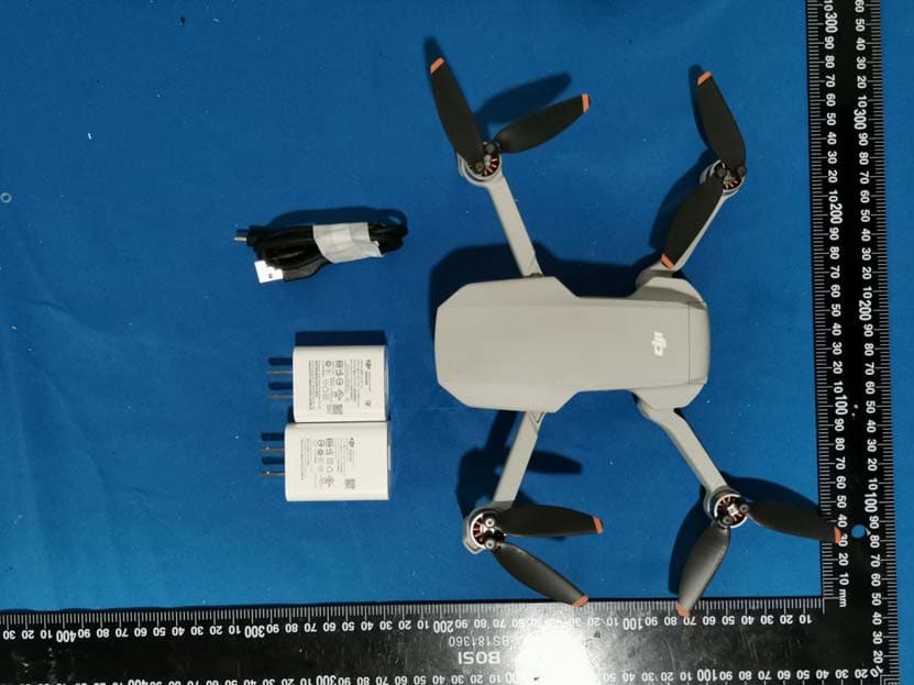
Click to zoom
Application Details
- Equipment Class
- NII - Unlicensed National Information Infrastructure TX
- Date of Grant
- Oct 05, 2020
- Application Purpose
- Original Equipment
- Date of Application
- Oct 04, 2020
- Equipment Note
- Camera Drone
- Frequency Range
- 5745.00000000 - 5825.00000000
- Company
- SZ DJI TECHNOLOGY CO., LTD
- Country
- China
Documents & Files
Document Text
Text extracted from the exhibit documents filed with the FCC. Open a document above to read the original.
Users Manual
Camera Drone Quick Start Guide V1.0 2020.07 Aircraft DJIMini 2features Obstacle Sensing and Infrared Sensing System * , and a fully stabilized 3‐axis gimbal with a 1/2.3” CMOS sensor camera that shoots 4K video and 12‐megapixel photos. 1. Gimbal and Camera 2. Power Button 3. Battery Level LEDs 4. Downward Vision System 5. Infrared Sensing System 6. Motors 7. Propellers 8. Antennas 9. Battery Cover 10. Charging/Upgrading Port (USB‐C) 11. microSD Card Slot 12. Aircraft Status Indicator Remote Controller Built into the remote controller is DJI’s long‐range transmission technology OCUSYNC TM 2.0, offering a maximum transmission range of 5 mi (8 km) and displaying video from the aircraft to DJI Fly on your mobile device at up to 1080p. 1. Power Button 2. Flight Mode Switch 3. Flight Pause/RTH Button 4. Battery Level LEDs 5. Control Sticks 6. Customizable Button 7. Photo/Video Toggle 8. Remote Controller Cable 9. Mobile Device Holder 10. USB‐C Port 11. Control Sticks Storage Slot 12. Gimbal Dial 13. Shoot/Record Button Download the DJI Fly App and Watching Tuto r i al Videos Search “DJI Fly” in the App Store or Google Play or scan the QR code below to download the app on your mobile device. Charging the Batteries Checking the Battery Levels and Powering On/Off Press once to check the battery level. Press, then press and hold to turn on/off. Preparing the Aircraft 1. Remove the gimbal cover from the camera. 2. Unfold the front arms and the propellers. 3. Unfold the rear arms and the propellers. 4. Unfolded Unfold the front arms and the propellers before the rear ones. All arms and propellers must be unfolded before takeoff. Preparing the Remote Controller 1. Attach the control sticks. 2. Pull out the mobile device holder, and then unplug the end with mobile phone mark of the RC cable. 3. Place the mobile device onto the mobile device holder, and plug the RC cable into the mobile device. Ensure the control sticks are firmly mounted. The remote controller cable with the Lightning connector is mounted by default. Use the appropriate cable for your mobile device to connect to the remote controller. Preparing for Ta ke o f f 1. Power on the remote controller 2. Power on the aircraft 3. LaunchDJI Fly App Flight • Remote Controller Operation Specifications •Aircraft (Model:MT2PD) Weight 241 g Max Flight Time 30 minutes (0 wind while flying at a consistent 15.5 mph (25 kph)) Operating Temperature 32° to 104°F (0° to 40°C) •Camera Sensor 1/2.3’’ CMOS; Effective pixels: 12M Lens FOV: 83° 35mm format equivalent: 24 mm Aperture: f/2.8 Focus: 1 m to ∞ ISO Range 100‐3200 Electronic Shutter Speed 4‐1/8000 s •Remote Controller Operating Voltage 1200mA @ 3.7V (Android) 700mA @ 3.7V (iOS) •Intelligent Flight Battery Capacity 2250 mAh Battery Type LiPo 2S Charging Temperature 41° to 113°F (5° to 45°C) Max Charging Power 29 W For more information, read the User Manual:http://www.dji.com/mini‐2 FCC Compliance Notice(For plane) This device complies with Part 15 of the FCC Rules. Operation is subject to the following two conditions: (1) This device may not cause harmful interference, and (2) This device must accept any interference received, including interference that may cause undesired operation. Any changes or modifications not expressly approved by the party responsible for compliance could void the user’s authority to operate the equipment. This equipment has been tested and found to comply with the limits for a Class B digital device, pursuant to part 15 of the FCC Rules. These limits are designed to provide reasonable protection against harmful interference in a residential installation. This equipment generates, uses and can radiate radio frequency energy and, if not installed and used in accordance with the instructions, may cause harmful interference to radio communications. However, there is no guarantee that interference will not occur in a particular installation. If this equipment does cause harmful interference to radio or television reception, which can be determined by turning the equipment off and on, the user is encouraged to try to correct the interference by one or more of the following measures: — Reorient or relocate the receiving antenna. — Increase the separation between the equipment and receiver. — Connect the equipment into an outlet on a circuit different from that to which the receiver is connected. — Consult the dealer or an experienced radio/TV technician for help. RF Exposure Information This equipment complies with FCC radiation exposure limits set forth for an uncontrolled environment. End user must follow the specific operating instructions for satisfying RF exposure compliance. This transmitter must not be co-located or operating in conjunction with any other antenna or transmitter. This equipment should be installed and operated with minimum distance 20cm between the radiator& your body. ISED Compliance Notice This device contains licence-exempt transmitter(s)/receiver(s) that comply with Innovation, Science and Economic Development Canada’s licence-exempt RSS(s). Operation is subject to the following two conditions: (1)This device may not cause interference.(2)This device must accept any interference, including interference that may cause undesired operation of the device. L’émetteur/récepteur exempt de licence contenu dans le présent appareil est conforme aux CNR d’I nnovation, Sciences et Développement économique Canada applicables aux appareils radio exempts de licence. L’exploitation est autorisée aux deux conditions suivantes :(1)L’appareil ne doit pas produire de brouillage; (2)L’appareil doit accepter tout brouillage radioélectrique subi, même si le brouillage est susceptible d’en compromettre le fonctionnement. This equipment complies with ISED radiation exposure limits set forth for an uncontrolled environment. End user must follow the specific operating instructions for satisfying RF exposure compliance. This transmitter must not be co-located or operating in con…
Text truncated - open the document above for the full version.
Cover Letter(s)
QA-FR-170-B SZ DJI TECHNOLOGY CO., LTD Add: 1 4th floor, West Wing, Skyworth Semiconductor Design Building NO.18 Gaoxin South 4th Ave, Nanshan District, Shenzhen, Guangdong, China Tel: 0755-86152250 Fax: 0755-86965903 E-mail:[email protected] FCC Authorization Date: 2020-09-11 FEDERAL COMMUNICATIONS COMMISSION Authorization and Evaluation Division 7435 Oakland Mills Road Columbia, MD 21046 Subject: Agent Authorization To whom it may concern: We , SZ DJI TECHNOLOGY CO., LTD, Hereby authorizes Bay Area Compliance Laboratories Corporation to act on its behalf in all matters relating to application for Equipment authorization, including the signing of all documents relating to these matters. All acts carried out by Bay Area Compliance Laboratory Corporation on our behalf shall have the same effect as our own action. We, the undersigned, hereby certify that we are not subject to a denial of federal benefits, that includes FCC benefits, pursuant to Section 5301 of the Anti-Drug Abuse Act of 1988, 21 U.S.C. 862. This authorization is valid until further written notice from the applicant. Sincerely Yours, Name: wang fajia Title:PM
Cover Letter(s)
QA-FR-172-A SZ DJI TECHNOLOGY CO., LTD Add: 14th floo r, West Wing, Skyworth Semiconductor Design Building NO.18 Gaoxin South 4th Ave, Nanshan District, Shenzhen, Guangdong, China Tel: 0755-86152250 Fax: 0755-86965903 E-mail:[email protected] FCC Confidential Authorization Date: 2020-09-11 FEDERAL COMMUNICATIONS COMMISSION Authorization and Evaluation Division 7435 Oakland Mills Road Columbia, MD 21046 Subject: Confidentiality Request regarding application for certification of FCC ID: SS3-MT2PD2007 In accordance with Sections 0.457 and 0.459 of the Commission’s Rules, SZ DJI TECHNOLOGY CO., LTD, hereby requests long-term confidential treatment of information accompanying this application as outlined below: Block Diagram Schematics Operation Description As well as short-term (secrecy cycle: 180days) confidential treatment of information application as outlined below: Internal Photos User’s Manual External Photos Test Set-up Photos The above materials contain proprietary and confidential information not customarily released to the public. The public disclosure of these materials provides unjustified benefits to its competitors in the market. Sincerely, Signature Name: wang fajia Title: PM
Cover Letter(s)
SZ DJI TECHNOLOGY CO., LTD Add: 14th floor, West Wing, Skyworth Semiconductor Design Building NO.18 Gaoxin South 4th Ave, Nanshan District, Shenzh en, Guangdong, China Tel: 0755-86152250 Fax: 0755-86965903 E-mail:[email protected] Date: 2020-09-11 To: FEDERAL COMMUNICATIONS COMMISSION Authorization and Evaluation Division 7435 Oakland Mills Road Columbia, MD 21046 Declaration Subject: FCC ID: SS3-MT2PD2007 declaration of restriction Dear Sir or Madam, We, SZ DJI TECHNOLOGY CO., LTD, hereby declare that our product Camera Drone, Model Number: MT2PD have the ability to work in 2.4G and 5G 4 frequency bands: 5150~5250MHz, 5 250~5350MHz, 5470~5725MHz, 5725~5850MHz. For the purpose of marketing, the frequency of the product sold in U.S. are programmed and locked to work only in 5725~5850MHz. The other 5150~5250MHz,5250~5350MHz, 5470~5725 MHz are disabled by firmware in factory. The end user or any other parties can not have the capability to activate the other frequency bands. We applied for testing frequency bands: 2 407.5~2465.5MHz,2409.12~2467.12MHz,2417.5~2456.5MHz, 2405.5~2476.5MHz,2410.5~2472.5MHz, 2412~2462MHz,2422-2452MHz 2 402~2480MHz,5728.5~5844.5MHz, 5730.12-5846.12MHz,5730.5-5844.5MHz, 5732.5MHz~5844.5MHz,5735.5MHz~5839.5MHz,5745-5825MHz for the United States this time in BACL. Ple a s e contact me if you have any question. Signature: Name: wang fajia Title:PM
External Photos
EXHIBIT B - EUT EXTERNAL PHOTOGRAPHS Adapter 1 Adapter 2
Internal Photos
EXHIBIT C - EUT INTERNAL PHOTOGRAPHS Antenna Location Antenna Chain 0(SDR Only) Antenna Chain 1(SDR/WIFI&BLE)
RF Exposure Info
Bay Area Compliance Laboratories Corp. (Dongguan) Report No.: RDG200810010-00E Page 13 of 80 FCC §15.407 (f) & §1.1310 & §2.1091- MAXIMUM PERMISSIBLE EXPOSURE (MPE) Applicable Standard According to subpart 15.407(f)and subpart §1.1310, systems operating under the provisions of this section shall be operated in a manner that ensures that the public is not exposed to radio frequency energy level in excess of the Commission’s guidelines. Limits for Maximum Permissible Exposure (MPE) (§1.1310, §2.1091) (B) Limits for General Population/Uncontrolled Exposure Frequency Range (MHz) Electric Field Strength (V/m) Magnetic Field Strength (A/m) Power Density (mW/cm 2 ) Averaging Time (minutes) 0.3–1.34 614 1.63 *(100) 30 1.34–30 824/f 2.19/f *(180/f²) 30 30–300 27.5 0.073 0.2 30 300–1500 / / f/1500 30 1500–100,000 / / 1.0 30 f = frequency in MHz; * = Plane-wave equivalent power density; According to §1.1310 and §2.1091 RF exposure is calculated. Calculation formula: Prediction of power density at the distance of the applicable MPE limit S = PG/4R² = power density (in appropriate units, e.g. mW/cm 2 ); P = power input to the antenna (in appropriate units, e.g., mW); G = power gain of the antenna in the direction of interest relative to an isotropic radiator, the power gain factor, is normally numeric gain; R = distance to the center of radiation of the antenna (appropriate units, e.g., cm); Calculated Data: Modes Frequency (MHz) Antenna Gain Conducted output power including Tune-up Tolerance Evaluation Distance (cm) Power Density (mW/cm 2 ) MPE Limit (mW/cm 2 ) (dBi) (numeric)(dBm)(mW) 2.4G Wi-Fi 2412-2462 2.5 1.78 24251.19 20.00 0.09 1.0 BLE 2402-2480 2.5 1.78 42.51 20.00 0.001 1.0 2.4G SDR 2405.5-2476.52.5 1.78 29794.33 20.00 0.28 1.0 5.8G Wi-Fi 5745-5825 3.5 2.24 1979.43 20.00 0.04 1.0 5.8G SDR 5728.5-5846.123.5 2.24 25316.23 20.00 0.14 1.0 Note: The Max. Target Power including Tolerance was declared by manufacturer. None of these 2.4GHz band or 5.8GHz band modes can transmit Simultaneously. Result: The device meet FCC MPE at 20 cm distance
Test Report
FCC PART 15.407 RSS-GEN, ISSUE 5, AMENDMENT 1, MARCH 2019 RSS-247, ISSUE 2, FEBRUARY 2017 TEST REPORT For SZ DJI TECHNOLOGY CO., LTD 14th floor, West Wing, Skyworth Semiconductor Design Building NO.18 Gaoxin South 4th Ave, Nanshan District, Shenzhen, Guangdong, China Report Type: Original Report Product Name: Camera Drone Re port Number: RDG200810010-00B Re port Date: 2020-09-05 Reviewed By: Ivan Cao Assistant Manager Test Laboratory: Bay Area Compliance Laboratories Corp. (Dongguan) No.69 Pulongcun, Puxinhu Industry Area, Tangxia, Dongguan, Guangdong, China Tel: +86-769-86858888 Fax: +86-769-86858891 www.baclcorp.com.cn FCC ID:SS3-MT2PD2007 IC:11805A-MT2PD2007 Bay Area Compliance Laboratories Corp. (Dongguan) Report No.: RDG200810010-00B Page 2 of 55 TABLE OF CONTENTS GENERAL INFORMATION ....................................................................................................................................... 4 PRODUCT DESCRIPTION FOR EQUIPMENT UNDER TEST (EUT) ..................................................................................... 4 OBJECTIVE ................................................................................................................................................................... 4 RELATED SUBMITTAL(S)/GRANT(S) ............................................................................................................................. 4 TEST METHODOLOGY .................................................................................................................................................. 5 MEASUREMENT UNCERTAINTY .................................................................................................................................... 5 TEST FACILITY ............................................................................................................................................................. 5 DECLARATIONS ............................................................................................................................................................ 5 SYSTEM TEST CONFIGURATION .......................................................................................................................... 6 DESCRIPTION OF TEST CONFIGURATION ...................................................................................................................... 6 EUT EXERCISE SOFTWARE .......................................................................................................................................... 6 EQUIPMENT MODIFICATIONS ....................................................................................................................................... 9 BLOCK DIAGRAM OF TEST SETUP ................................................................................................................................ 9 SUMMARY OF TEST RESULTS ............................................................................................................................. 10 FCC §15.407 (f) & §1.1310 & §2.1091- MAXIMUM PERMISSIBLE EXPOSURE (MPE) ...................................... 11 APPLICABLE STANDARD ............................................................................................................................................ 11 RSS-102 § 2.5.2 - EXEMPTION LIMITS FOR ROUTINE EVALUATION – RF EXPOSURE EVALUATION ............................................................................................................................................................ 12 APPLICABLE STANDARD ............................................................................................................................................ 12 FCC §15.203& RSS-GEN CLAUSE 6.8 - ANTENNA REQUIREMENT .............................................................. 13 APPLICABLE STANDARD ............................................................................................................................................ 13 ANTENNA CONNECTOR CONSTRUCTION .................................................................................................................... 14 FCC §15.209, §15.205 , §15.407(b) &RSS-247 CLAUSE 6.2, RSS-GEN CLAUSE 8.10 –UNWANTED EMISSION ................................................................................................................................................................... 15 APPLICABLE STANDARD ............................................................................................................................................ 15 EUT SETUP ................................................................................................................................................................ 17 EMI TEST RECEIVER & SPECTRUM ANALYZER SETUP .............................................................................................. 19 TEST PROCEDURE ...................................................................................................................................................... 19 CORRECTED AMPLITUDE & MARGIN CALCULATION ................................................................................................. 20 TEST EQUIPMENT LIST AND DETAILS ......................................................................................................................... 21 TEST DATA ................................................................................................................................................................ 21 FCC §15.407(a)(e) & RSS-247 CLAUSE 6.2,RSS-Gen CLAUSE 6.7–EMISSION BANDWIDTH AND OCCUPIED BANDWIDTH ....................................................................................................................................... 31 APPLICABLE STANDARD ............................................................................................................................................ 31 TEST EQUIPMENT LIST AND DETAILS .....................................…
Text truncated - open the document above for the full version.
Test Report
FCC PART 15.407 RSS-GEN, ISSUE 5, AMENDMENT 1, MARCH 2019 RSS-247, ISSUE 2, FEBRUARY 2017 TEST REPORT For SZ DJI TECHNOLOGY CO., LTD 14th floor, West Wing, Skyworth Semiconductor Design Building NO.18 Gaoxin South 4th Ave, Nanshan District, Shenzhen, Guangdong, China Report Type: Original Report Product Name: Camera Drone Re port Number: RDG200810010-00E Re port Date: 2020-09-05 Reviewed By: Ivan Cao Assistant Manager Test Laboratory: Bay Area Compliance Laboratories Corp. (Dongguan) No.69 Pulongcun, Puxinhu Industry Area, Tangxia, Dongguan, Guangdong, China Tel: +86-769-86858888 Fax: +86-769-86858891 www.baclcorp.com.cn FCC ID:SS3-MT2PD2007 IC:11805A-MT2PD2007 Bay Area Compliance Laboratories Corp. (Dongguan) Report No.: RDG200810010-00E Page 2 of 80 TABLE OF CONTENTS GENERAL INFORMATION ....................................................................................................................................... 4 PRODUCT DESCRIPTION FOR EQUIPMENT UNDER TEST (EUT) ..................................................................................... 4 OBJECTIVE ................................................................................................................................................................... 4 RELATED SUBMITTAL(S)/GRANT(S) ............................................................................................................................. 5 TEST METHODOLOGY .................................................................................................................................................. 5 MEASUREMENT UNCERTAINTY .................................................................................................................................... 5 TEST FACILITY ............................................................................................................................................................. 5 DECLARATIONS ............................................................................................................................................................ 5 SYSTEM TEST CONFIGURATION .......................................................................................................................... 7 DESCRIPTION OF TEST CONFIGURATION ...................................................................................................................... 7 EUT EXERCISE SOFTWARE .......................................................................................................................................... 8 EQUIPMENT MODIFICATIONS ..................................................................................................................................... 11 BLOCK DIAGRAM OF TEST SETUP .............................................................................................................................. 11 SUMMARY OF TEST RESULTS ............................................................................................................................. 12 FCC §15.407 (f) & §1.1310 & §2.1091- MAXIMUM PERMISSIBLE EXPOSURE (MPE) ...................................... 13 APPLICABLE STANDARD ............................................................................................................................................ 13 RSS-102 § 2.5.2 - EXEMPTION LIMITS FOR ROUTINE EVALUATION – RF EXPOSURE EVALUATION ............................................................................................................................................................ 14 APPLICABLE STANDARD ............................................................................................................................................ 14 FCC §15.203& RSS-GEN CLAUSE 6.8 - ANTENNA REQUIREMENT .............................................................. 15 APPLICABLE STANDARD ............................................................................................................................................ 15 ANTENNA CONNECTOR CONSTRUCTION .................................................................................................................... 16 FCC §15.209, §15.205 , §15.407(b) &RSS-247 CLAUSE 6.2, RSS-GEN CLAUSE 8.10 –UNWANTED EMISSION ................................................................................................................................................................... 17 APPLICABLE STANDARD ............................................................................................................................................ 17 EUT SETUP ................................................................................................................................................................ 19 EMI TEST RECEIVER & SPECTRUM ANALYZER SETUP .............................................................................................. 21 TEST PROCEDURE ...................................................................................................................................................... 21 CORRECTED AMPLITUDE & MARGIN CALCULATION ................................................................................................. 22 TEST EQUIPMENT LIST AND DETAILS ......................................................................................................................... 23 TEST DATA ................................................................................................................................................................ 23 FCC §15.407(a)(e) & RSS-247 CLAUSE 6.2,RSS-Gen CLAUSE 6.7–EMISSION BANDWIDTH AND OCCUPIED BANDWIDTH ....................................................................................................................................... 39 APPLICABLE STANDARD ............................................................................................................................................ 39 TEST EQUIPMENT LIST AND DETAILS .......................................…
Text truncated - open the document above for the full version.
Test Setup Photos
EXHIBIT D - TEST SETUP PHOTOGRAPHS Radiated Emission Below 1GHz View Radiated Emission Above 1GHz View
Contact Information
Applicant
Gary Zeng(PM)
Test Firm
Bay Area Compliance Laboratories Corp.(Dongguan)David Zhang
[email protected]0086 0769 86858888
Technical Specifications
| # | Rule Parts | Frequency Range | Power Output |
|---|---|---|---|
| 6 | 15E | 5.75 GHz - 5.83 GHz | 65.00 mW |
Other Applications from SZ DJI TECHNOLOGY CO., LTD
SS3-T55A2510
Dec 19, 2025DJI AGRAS T55
Equipment Class
NII - Unlicensed National Information Infrastructure TXSS3-T100A2510
Dec 19, 2025DJI AGRAS T100S, DJI AGRAS T70S
Equipment Class
NII - Unlicensed National Information Infrastructure TXSS3-TKMI2507
Dec 19, 2025DJI RC Mini
Equipment Class
DTS - Digital Transmission SystemSS3-RD60B2510
Dec 18, 2025Fixed Millimeter Wave Radar
Equipment Class
FDS - Part 15 Field Disturbance SensorSS3-RD60A2510
Dec 18, 2025Rotational Active Phased Array Radar
Equipment Class
FDS - Part 15 Field Disturbance Sensor