SS3-RD2424ROmnidirectional Digital Radar/CSM Radar
SZ DJI TECHNOLOGY CO., LTD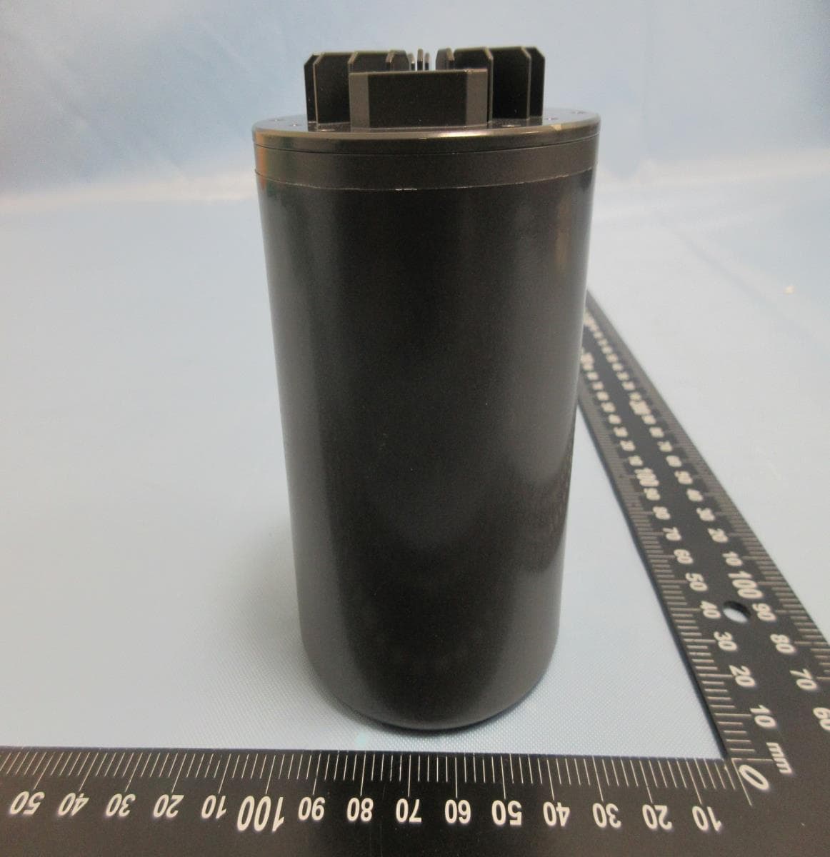
Click to zoom
Application Details
- Equipment Class
- DXX - Part 15 Low Power Communication Device Transmitter
- Date of Grant
- Mar 07, 2021
- Application Purpose
- Original Equipment
- Date of Application
- Mar 07, 2021
- Equipment Note
- Omnidirectional Digital Radar/CSM Radar
- Frequency Range
- 24150.00000000 - 24150.00000000
- Company
- SZ DJI TECHNOLOGY CO., LTD
- Country
- China
Documents & Files
Document Text
Text extracted from the exhibit documents filed with the FCC. Open a document above to read the original.
Users Manual
AGRAS T10 Quick Start Guide v1.0 Aircraft The AGRAS TM T10 features a design including a brand-new quadrilateral folding structure and a quick-release spray tank and flight battery, making replacement, installation, and storage easy. With the updated Route Operation mode users can mark obstacles outside of the operation area for Smart Continuous Flight. The aircraft supports centimeter-level positioning when used with the onboard D-RTK TM . Dual-antenna technology provides strong resistance against magnetic interference. The aircraft comes equipped with the Spherical Perception Radar System, a pioneering new system for the agriculture industry. Consisting of the Omnidirectional Digital Radar and Upward Radar, the system provides functions such as terrain following, obstacle sensing, and obstacle circumventing. With the forward and backward FPV cameras and bright spotlights, the system comprehensively ensures operational safety day and night in different weather. The spraying system adopts a 10 L spray tank, four nozzles, and a 2-channel electromagnetic flow meter to ensure consistent and accurate spraying, save the pesticide, and reduce operating costs effectively. Core components have two layers of protection and the aircraft has a protection rating of IP67 (IEC standard 60529, except for the Intelligent Flight Battery) so that it can be washed directly with water. 1. Propellers 2. Motors 3. ESCs 4. Aircraft Front Indicators (on two front arms) 5. Frame Arms 6. Folding Detection Sensors (built-in) 7. Hoses 8. Sprinklers 9. Electromagnetic Exhaust Valves 10. Nozzles 11. Omnidirectional Digital Radar 12. Upward Radar (built-in) 13. Heat Sinks 14. Spread Tank 15. Battery Compartment 16. Forward FPV Camera 17. Backward FPV Camera 18. Landing Gear 19. OCUSYNC TM Antennas 20. Onboard D-RTK TM Antennas 21. Aircraft Status Indicators (on two rear arms) Rear View Folded Remote Controller The Smart Controller Enterprise uses DJI OcuSync Enterprise transmission technology, has a max transmission distance of up to 7 km*, and supports Wi-Fi and Bluetooth. The remote controller has a 5.5-inch bright, dedicated screen and comes with the updated DJI Agras app built-in, delivering a smooth and easy-to-use experience. When the RTK dongle is connected to the remote controller, users can plan operations to centimeter-level precision. The Multi-Aircraft Control mode* of the remote controller can be used to coordinate the operation of up to five aircraft at the same time, enabling pilots to work efficiently. Both the built-in battery and external battery can be used to supply power to the remote controller. The remote controller has a working time of up to 4 hours, making it ideal for long and high-intensity operations. The figure below shows the function that each control stick movement performs and uses Mode 2 as an example. In Mode 2, the left stick is used to control the altitude and heading of the aircraft while the right stick is used to control the forward, backward, left, and right movements. 1. Antennas 2. Back/Function Button 3. Control Stick 4. RTH Button 5. Button C3 (customizable) 6. Flight Mode Switch 7. Status LED Descriptions 8. Battery Level Indicators 9. 5D Button (customizable) 10. Power Button 11. Confirm Button 12. Touch Screen 13. USB-C Charging Port 14. Dongle Compartment Cover 15. Spray Rate Dial 16. Spray Button 17. HDMI Port 18. microSD Card Slot 19. USB-A Port 20. FPV/Map Switch Button 21. Work Efficiency Dial 22. Air Outlet 23. Button C1 (customizable) 24. Button C2 (customizable) 25. Battery Cover 26. Battery Cover Release Button 27. Handle * The remote controller is able to reach its maximum transmission distance (FCC/NCC: 7 km (4.35 mi); SRRC: 5 km (3.11 mi); CE/KCC/MIC: 4 km (2.49 mi)) in an open area with no electromagnetic interference, and at an altitude of approximately 2.5 m (8.2 ft). Make sure to comply with local laws and regulations when using Multi-Aircraft Control mode. Fly Safe It is important to understand some basic flight guidelines, both for your protection and for the safety of those around you. 1. Flying in Open Areas: pay attention to utility poles, power lines, and other obstacles. DO NOT fly near or above water, people, or animals. 2. Maintain Control at All Times: keep your hands on the remote controller and maintain control of the aircraft when it is in flight, even when using intelligent functions such as the Route and A-B Route operation modes and Smart Return to Home. 3. Maintain Line of Sight: maintain visual line of sight (VLOS) with your aircraft at all times and avoid flying behind buildings or other obstacles that may block your view. 4. Monitor Your Altitude: for the safety of manned aircraft and other air traffic, fly at altitudes lower than 30 m (98 ft) and in accordance with all local laws and regulations. Visit https://www.dji.com/flysafe for more information on critical safety features such as GEO zones. Flight Environment Requirements 1. DO NOT use the aircraft to spray in winds exceeding 18 kph (11 mph). 2. DO NOT use the aircraft in adverse weather conditions such as winds exceeding 28 kph (17 mph), heavy rain exceeding 25 mm (0.98 in) in 12 hours, snow, or fog. 3. DO NOT fly more than 4.5 km (14,763 ft) above sea level. 4. Once the operating altitude reaches 1 km (3,280 ft), the payload capacity of the spray tank is reduced by 1.2 kg. For every additional km, the payload capacity will be reduced a further 1.2 kg. 5. Make sure that there is a strong GNSS signal and the D-RTK antennas are unobstructed during operation. Return to Home (RTH) The aircraft will automatically return to the Home Point in the following situations: Smart RTH: user presses and holds the RTH button. Failsafe RTH: the remote controller signal is lost.* If there is an obstacle within 20 m of the aircraft, the aircraft decelerates and brakes and hovers. If the aircraft comes within 6 m of the obstacle while decelerating, the aircraft brakes, flies backward to approx. 6…
Text truncated - open the document above for the full version.
External Photos
Appendix EP Photographs of EUT Page 1 of 17 CN21478R(P15C-24GHz) 001, CN21478R(FCC-MPE) 001, CN21CESJ(RSS210-24GHz) 001, CN21CESJ(IC-MPE) 001 Product: Omnidirectional Digital Radar/CSM Radar Type Identification: RD2424R Appendix EP Photographs of EUT Page 2 of 17 CN21478R(P15C-24GHz) 001, CN21478R(FCC-MPE) 001, CN21CESJ(RSS210-24GHz) 001, CN21CESJ(IC-MPE) 001 Product: Omnidirectional Digital Radar/CSM Radar Type Identification: RD2424R Appendix EP Photographs of EUT Page 3 of 17 CN21478R(P15C-24GHz) 001, CN21478R(FCC-MPE) 001, CN21CESJ(RSS210-24GHz) 001, CN21CESJ(IC-MPE) 001 Product: Omnidirectional Digital Radar/CSM Radar Type Identification: RD2424R Appendix EP Photographs of EUT Page 4 of 17 CN21478R(P15C-24GHz) 001, CN21478R(FCC-MPE) 001, CN21CESJ(RSS210-24GHz) 001, CN21CESJ(IC-MPE) 001 Product: Omnidirectional Digital Radar/CSM Radar Type Identification: RD2424R
ID Label/Location Info
M/N: RD2424R Label and Label Location
ID Label/Location Info
M/N: RD2424R Label and Label Location
Internal Photos
Appendix EP Photographs of EUT Page 4 of 17 CN21478R(P15C-24GHz) 001, CN21478R(FCC-MPE) 001, CN21CESJ(RSS210-24GHz) 001, CN21CESJ(IC-MPE) 001 Product: Omnidirectional Digital Radar/CSM Radar Type Identification: RD2424R Appendix EP Photographs of EUT Page 5 of 17 CN21478R(P15C-24GHz) 001, CN21478R(FCC-MPE) 001, CN21CESJ(RSS210-24GHz) 001, CN21CESJ(IC-MPE) 001 Product: Omnidirectional Digital Radar/CSM Radar Type Identification: RD2424R Appendix EP Photographs of EUT Page 6 of 17 CN21478R(P15C-24GHz) 001, CN21478R(FCC-MPE) 001, CN21CESJ(RSS210-24GHz) 001, CN21CESJ(IC-MPE) 001 Product: Omnidirectional Digital Radar/CSM Radar Type Identification: RD2424R Appendix EP Photographs of EUT Page 7 of 17 CN21478R(P15C-24GHz) 001, CN21478R(FCC-MPE) 001, CN21CESJ(RSS210-24GHz) 001, CN21CESJ(IC-MPE) 001 Product: Omnidirectional Digital Radar/CSM Radar Type Identification: RD2424R Appendix EP Photographs of EUT Page 8 of 17 CN21478R(P15C-24GHz) 001, CN21478R(FCC-MPE) 001, CN21CESJ(RSS210-24GHz) 001, CN21CESJ(IC-MPE) 001 Product: Omnidirectional Digital Radar/CSM Radar Type Identification: RD2424R Appendix EP Photographs of EUT Page 9 of 17 CN21478R(P15C-24GHz) 001, CN21478R(FCC-MPE) 001, CN21CESJ(RSS210-24GHz) 001, CN21CESJ(IC-MPE) 001 Product: Omnidirectional Digital Radar/CSM Radar Type Identification: RD2424R Appendix EP Photographs of EUT Page 10 of 17 CN21478R(P15C-24GHz) 001, CN21478R(FCC-MPE) 001, CN21CESJ(RSS210-24GHz) 001, CN21CESJ(IC-MPE) 001 Product: Omnidirectional Digital Radar/CSM Radar Type Identification: RD2424R Appendix EP Photographs of EUT Page 11 of 17 CN21478R(P15C-24GHz) 001, CN21478R(FCC-MPE) 001, CN21CESJ(RSS210-24GHz) 001, CN21CESJ(IC-MPE) 001 Product: Omnidirectional Digital Radar/CSM Radar Type Identification: RD2424R Appendix EP Photographs of EUT Page 12 of 17 CN21478R(P15C-24GHz) 001, CN21478R(FCC-MPE) 001, CN21CESJ(RSS210-24GHz) 001, CN21CESJ(IC-MPE) 001 Product: Omnidirectional Digital Radar/CSM Radar Type Identification: RD2424R Appendix EP Photographs of EUT Page 13 of 17 CN21478R(P15C-24GHz) 001, CN21478R(FCC-MPE) 001, CN21CESJ(RSS210-24GHz) 001, CN21CESJ(IC-MPE) 001 Product: Omnidirectional Digital Radar/CSM Radar Type Identification: RD2424R Antenna Appendix EP Photographs of EUT Page 14 of 17 CN21478R(P15C-24GHz) 001, CN21478R(FCC-MPE) 001, CN21CESJ(RSS210-24GHz) 001, CN21CESJ(IC-MPE) 001 Product: Omnidirectional Digital Radar/CSM Radar Type Identification: RD2424R Appendix EP Photographs of EUT Page 15 of 17 CN21478R(P15C-24GHz) 001, CN21478R(FCC-MPE) 001, CN21CESJ(RSS210-24GHz) 001, CN21CESJ(IC-MPE) 001 Product: Omnidirectional Digital Radar/CSM Radar Type Identification: RD2424R Appendix EP Photographs of EUT Page 16 of 17 CN21478R(P15C-24GHz) 001, CN21478R(FCC-MPE) 001, CN21CESJ(RSS210-24GHz) 001, CN21CESJ(IC-MPE) 001 Product: Omnidirectional Digital Radar/CSM Radar Type Identification: RD2424R Appendix EP Photographs of EUT Page 17 of 17 CN21478R(P15C-24GHz) 001, CN21478R(FCC-MPE) 001, CN21CESJ(RSS210-24GHz) 001, CN21CESJ(IC-MPE) 001 Product: Omnidirectional Digital Radar/CSM Radar Type Identification: RD2424R
Test Report
Prü fbericht - Produkte Test Report - Products Prü fbericht-Nr.: Test report no.: CN21478R(P15C-24GHz) 001 Auftrags-Nr.: Order no.: 238495708 Seite 1 von 24 Page 1 of 24 Kunden-Referenz-Nr.: Client reference no.: N/A Auftragsdatum: Order date: 2020-12-28 Auftraggeber: Client: SZ DJI TECHNOLOGY CO.,LTD. 14th floor, West Wing, Skyworth Semiconductor Design Building NO.18 Gaoxin South 4th Ave, Nanshan, Shenzhen, Guangdong, China Prü fgegenstand: Test item: Omnidirectional Digital Radar/CSM Radar Bezeichnung / Typ-Nr.: Identification / Type no.: RD2424R Auftrags-Inhalt: Order content: FCC Part 15C Test report Prü fgrundlage: Test specification: FCC 47CFR Part 15: Subpart C Section 15.249 Wareneingangsdatum: Date of sample receipt: 2020-12-11 Prü fmuster-Nr.: Test sample no: A002967117-006 Prü fzeitraum: Testing period: 2021-01-18 - 2021-03-19 Ort der Prü fung: Place of testing: EMC/RF Taipei Testing Site Prü flaboratorium: Testing laboratory: Taipei Testing Laboratories Prü fergebnis*: Test result*: Pass überprü ft von: reviewed by: Mars Lin genehmigt von: authorized by: Brenda Chen Datum: Date: 2021-03-22 Ausstellungsdatum: Issue date: 2021-03-22 Stellung / Position: Senior Project Engineer Stellung / Position: Senior Project Manager Sonstiges / Other: This EUT contains two 24G modules, supporting 1T1R and 2T4R respectively. Zustand des Prü fgegenstandes bei Anlieferung: Condition of the test item at delivery: Prüfmuster vollständig und unbeschädigt Test item complete and undamaged * Legende: 1 = sehr gut 2 = gut 3 = bef riedigend 4 = ausreichend 5 = mangelhaf t P(ass) = entspricht o.g. Prüfgrundlage(n) F(ail) = entspricht nicht o.g. Prüfgrundlage(n) N/A = nicht anwendbar N/T = nicht getestet * Legend: 1 = very good 2 = good 3 = satisfactory 4 = sufficient 5 = poor P(ass) = passed a.m. test specification(s) F(ail) = failed a.m. test specification(s) N/A = not applicable N/T = not tested Dieser Prü fbericht bezieht sich nur auf das o.g. Prü fm uster und darf ohne Genehm igung der Prü fstelle nicht auszugsw eise vervielfältigt w erden. Dieser Bericht berechtigt nicht zur Verwendung eines Prü fzeichens. This test report only relates to the a. m. test sample. Without permission of the test center this test report is not permitted to be duplicated in extracts. This test report does not entitle to carry any test mark. T UV Rheinland T aiwan Ltd. 11F., No. 758, Sec. 4, Bade Rd., T aipei 105, T aiwan, R.O.C. Mail: [email protected] ∙ Web: www.tuv.com Prü fbericht - Produkte Test Report - Products Prü fbericht - Nr.: Test Report No. CN21478R(P15C-24GHz) 001 Seite 2 von 24 Page 2 of 24 TEST SUMMARY Report Section FCC Clause Test Item Result 5.1.1 15.203 Antenna Requirement Pass 5.1.2 15.215 20 dB Bandwidth Pass 5.1.2 2.1049 99% Occupied Bandwidth Pass 5.1.3 15.249 (a) Field Strength of Fundamental Emissions Pass 5.1.4 15.249 (d) Radiated Spurious Emissions Pass 5.2.1 15.207 Mains Conducted Emission Not Applicable Note: Determining compliance based on the results of the compliance measurement, not taking into account measurement instrumentation uncertainty. Prü fbericht - Produkte Test Report - Products Prü fbericht - Nr.: Test Report No. CN21478R(P15C-24GHz) 001 Seite 3 von 24 Page 3 of 24 Contents HISTORY OF THIS TEST REPORT .................................................................................. 4 1. GENERAL REMARKS .................................................................................................. 5 1.1 COMPLEMENTARY MATERIALS ................................................................................... 5 1.2 DECISION RULE OF CONFORMITY ............................................................................... 5 2. TEST SITES................................................................................................................ 6 2.1 TEST LABORATORY ................................................................................................... 6 2.2 TEST FACILITY ........................................................................................................... 6 2.3 TRACEABILITY ........................................................................................................... 7 2.4 CALIBRATION............................................................................................................. 7 2.5 MEASUREMENT UNCERTAINTY ................................................................................... 7 3. GENERAL PRODUCT INFORMATION ............................................................................ 8 3.1 PRODUCT FUNCTION AND INTENDED USE ................................................................... 8 3.2 SYSTEM DETAILS AND RATINGS ................................................................................. 8 3.3 NOISE GENERATING AND NOISE SUPPRESSING PARTS............................................... 9 3.4 SUBMITTED DOCUMENTS ........................................................................................... 9 4. TEST SET-UP AND OPERATION MODES .................................................................... 10 4.1 PRINCIPLE OF CONFIGURATION SELECTION.............................................................. 10 4.2 TEST OPERATION AND TEST SOFTWARE .................................................................. 10 4.3 SPECIAL ACCESSORIES AND AUXILIARY EQUIPMENT................................................ 11 4.4 TEST SETUP DIAGRAM............................................................................................. 12 5. TEST RESULTS ........................................................................................................ 13 5.1 TRANSMITTER REQUIREMENT & TEST SUITES .......................................................... 13 5.1.1 Antenna Requirement ............................................................................................. 13 5.1.2 20 dB Bandwidth and 99% Occupied Bandwidth.......................................................... 14…
Text truncated - open the document above for the full version.
Test Setup Photos
Appendix SP Photographs of Test Setup Page 1 of 6 CN21478R(P15C-24GHz) 001, CN21478R(FCC-MPE) 001, CN21CESJ(RSS210-24GHz) 001, CN21CESJ(IC-MPE) 001 Product: Omnidirectional Digital Radar/CSM Radar Type Identification: RD2424R Photograph 1: Test Setup for Spurious Emissions (Front View 1) Photograph 2: Test Setup for Spurious Emissions (Front View 2) Appendix SP Photographs of Test Setup Page 2 of 6 CN21478R(P15C-24GHz) 001, CN21478R(FCC-MPE) 001, CN21CESJ(RSS210-24GHz) 001, CN21CESJ(IC-MPE) 001 Product: Omnidirectional Digital Radar/CSM Radar Type Identification: RD2424R Photograph 3: Test Setup for Spurious Emissions (Back View 1) Photograph 4: Test Setup for Spurious Emissions (Back View 2) Appendix SP Photographs of Test Setup Page 3 of 6 CN21478R(P15C-24GHz) 001, CN21478R(FCC-MPE) 001, CN21CESJ(RSS210-24GHz) 001, CN21CESJ(IC-MPE) 001 Product: Omnidirectional Digital Radar/CSM Radar Type Identification: RD2424R Photograph 5: Test Setup for Spurious Emissions (Back View 3) Photograph 6: Test Setup for Spurious Emissions (Back View 4) Appendix SP Photographs of Test Setup Page 4 of 6 CN21478R(P15C-24GHz) 001, CN21478R(FCC-MPE) 001, CN21CESJ(RSS210-24GHz) 001, CN21CESJ(IC-MPE) 001 Product: Omnidirectional Digital Radar/CSM Radar Type Identification: RD2424R Photograph 7: Test Setup for Spurious Emissions (Back View 5) Photograph 8: Test Setup for Spurious Emissions (Back View 6) Appendix SP Photographs of Test Setup Page 5 of 6 CN21478R(P15C-24GHz) 001, CN21478R(FCC-MPE) 001, CN21CESJ(RSS210-24GHz) 001, CN21CESJ(IC-MPE) 001 Product: Omnidirectional Digital Radar/CSM Radar Type Identification: RD2424R Photograph 9: Test Setup for Spurious Emissions (Back View 7) Appendix SP Photographs of Test Setup Page 6 of 6 CN21478R(P15C-24GHz) 001, CN21478R(FCC-MPE) 001, CN21CESJ(RSS210-24GHz) 001, CN21CESJ(IC-MPE) 001 Product: Omnidirectional Digital Radar/CSM Radar Type Identification: RD2424R Support Units
Contact Information
Applicant
Gary Zeng(PM)
Technical Contact
Test Firm
TUV Rheinland Taiwan Ltd. Taipei Testing Lab.Kenji Lin
Technical Specifications
| # | Rule Parts | Frequency Range | Power Output |
|---|---|---|---|
| 1 | 15C | 24.15 GHz - 24.15 GHz | - |
Other Applications from SZ DJI TECHNOLOGY CO., LTD
SS3-T55A2510
Dec 19, 2025DJI AGRAS T55
Equipment Class
NII - Unlicensed National Information Infrastructure TXSS3-T100A2510
Dec 19, 2025DJI AGRAS T100S, DJI AGRAS T70S
Equipment Class
NII - Unlicensed National Information Infrastructure TXSS3-TKMI2507
Dec 19, 2025DJI RC Mini
Equipment Class
DTS - Digital Transmission SystemSS3-RD60B2510
Dec 18, 2025Fixed Millimeter Wave Radar
Equipment Class
FDS - Part 15 Field Disturbance SensorSS3-RD60A2510
Dec 18, 2025Rotational Active Phased Array Radar
Equipment Class
FDS - Part 15 Field Disturbance Sensor