SS3-WM3211503Phantom 3 Standard
SZ DJI TECHNOLOGY CO., LTD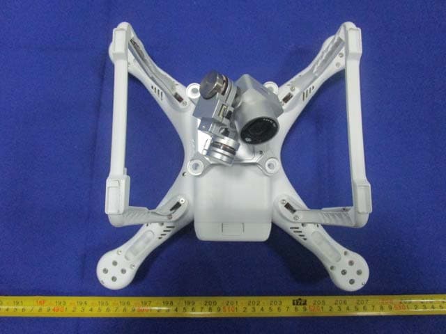
Click to zoom
Application Details
- Equipment Class
- DTS - Digital Transmission System
- Date of Grant
- Jul 20, 2015
- Application Purpose
- Original Equipment
- Date of Application
- Jul 20, 2015
- Equipment Note
- Phantom 3 Standard
- Frequency Range
- 2412.00000000 - 2462.00000000
- Company
- SZ DJI TECHNOLOGY CO., LTD
- Country
- China
Documents & Files
Document Text
Text extracted from the exhibit documents filed with the FCC. Open a document above to read the original.
Users Manual
PHANTOM 3 V1.0 2015.04 User Manual Standard 2 © 2015 DJI. All Rights Reserved. Using this manual Legends WarningImportantHints and TipsReference Read Before the First Flight Read the following documents before using the Phantom 3 Standard: 1. In the Box 2. Phantom 3 Standard User Manual 3. Phantom 3 Standard Quick Start Guide 4. Phantom 3 Standard Guidelines and Disclaimer 5. Phantom 3 Standard Intelligent Flight Battery Safety Guidelines We recommend that you watch all tutorial videos on the official DJI website and read the Disclaimer before you fly. Prepare for your first flight by reviewing the Phantom 3 Standard Quick Start Guide and refer to the User Manual for more detailed information . Video Tutorials Please watch the tutorial videos at the link below, which demonstrates how to use Phantom 3 Standard aircraft http://www.dji.com/product/phantom-3/video Download the DJI Pilot app Download and install the DJI Pilot app before using the aircraft. Scan the QR code to the right to download the latest version. The Android version of the DJI Pilot app is compatible with Android 4.1.2 or later. The iOS version of the DJI Pilot app is compatible with iOS 8.0 or later. © 2015 DJI. All Rights Reserved. 3 Contents Using this manual Legends 2 Read Before the First Flight 2 Video Tutorials 2 Download the DJI Pilot app 2 Product Profile Introduction 6 Feature Highlights 6 Preparing the Aircraft 7 Aircraft Diagram 8 Remote Controller Diagram 8 Aircraft Flight Controller 11 Flight Mode 11 Flight Status Indicator 11 Return-to-Home (RTH) 12 Smart RTH 12 Low Battery RTH 13 Failsafe RTH 14 Vision Positioning System 14 Flight Recorder 16 Attaching and Detaching the Propellers 16 DJI Intelligent Flight Battery 17 Remote Controller Remote Controller Profile 23 Using the Remote Controller 23 Remote Controller Status LED 27 Linking the Remote Controller 28 Remote Controller Compliance Version 29 4 © 2015 DJI. All Rights Reserved. Camera and Gimbal Camera Profile 31 Gimbal 32 DJI Pilot App Camera 35 Director 38 Store 38 Discovery 38 Flight Flight Environment Requirements 40 Flight Limits and No-Fly Zones 40 Preflight Checklist 44 Calibrating the Compass 44 Auto Takeoff and Auto Landing 45 Flight Test 46 Starting/Stopping the Motors 46 Troubleshooting (FAQ) Appendix Specifications 53 Intelligent Orientation Control (IOC) 55 FCC Compliance 56 © 2015 DJI. All Rights Reserved. 5 Product Profile This section introduces the Phantom 3 Standard and lists the components of the aircraft and remote controller. 6 © 2015 DJI. All Rights Reserved. Product Profile Product Profile Introduction The Phantom 3 Standard represents the next generation of DJI quadcopters. It is capable of capturing 1080P video and video signal out of the box. The built-in camera has an integrated gimbal to maximize stability while minimizing both weight and size. Feature Highlights Camera and Gimbal: With the Phantom 3 Standard, you’re shooting 1080p video and capturing 12 megapixel pho- tos that look crisper and cleaner than ever. An enhanced sensor gives you greater clarity, lower noise, and better pictures than any previous flying camera. DJI Intelligent Flight Battery: The 4480 mAh DJI Intelligent Flight Battery features upgraded battery cells and an advanced power management system. Built-in WiFi Extender: The wifi extender is integrated into the remote controller to allow a easy connection to teh aircraft. Flight Controller: The next-generation flight controller has been updated to provide a safer, more reliable flight experience. A newly implemented flight recorder stores critical data from each flight. © 2015 DJI. All Rights Reserved. 7 Product Profile Phantom 3 Standard User Manual Preparing the Aircraft Removing Gimbal Clamp Remove the gimbal clamp by sliding it to the right (when facing the nose of the aircraft), as shown below. Attaching the Propellers: Mount the propellers with black dots on to motors with black axes and spin counter-clockwise to secure. Mount the propellers with sliver dots on to motors with sliver axes and spin clockwise to secure. Be sure all propellers are securely in place. Preparing the Remote Controller: 1. Twist the Phone Holder to face outwards and fix in position. 2 . Ensure the battery is fully charged. 3. Be sure S1 and S2 are switched to the upper most position. The LED will go green if the Remote Controller is functioning. Place all propellers onto the correct motors and tighten by hand to lock them in position. S1S2 8 © 2015 DJI. All Rights Reserved. Product Profile Phantom 3 Standard User Manual Aircraft Diagram [1] Gimbal and Camera [2] Camera Micro-SD Card Slot [3] Aircraft Micro-USB Port [4] Front LED Indicator [5] Landing gear [6] Motor [7] Rear LED Indicator [8] Antennas [10] [11] © 2015 DJI. All Rights Reserved. 9 Product Profile Phantom 3 Standard User Manual Remote Controller Diagram [1] Power Button [2] Status LED [3] Battery Level LEDs [4] Neck Strap Securing Hole [5] S1 Switch [6] S2 Switch [7] Control Stick [8] Phone Holder [9] Antennas [10] Gimbal Dial [11] Charging Port 10 © 2015 DJI. All Rights Reserved. Aircraft This section introduces the features of the Flight Controller, Vision Positioning System, and the Intelligent Flight Battery © 2015 DJI. All Rights Reserved. 11 Aircraft Flight Status Indicator The Phantom 3 Standard has Front LEDs and Aircraft Status Indicators. The positions of these LEDs are shown in the figure below: The Front LEDs show the orientation of the aircraft. The Front LEDs glow solid red when the aircraft is turned on to indicate the front (or nose) of the aircraft. The Aircraft Status Indicators communicate the system status of the flight controller. Refer to the table below for more information about the Aircraft Status Indicators: Aircraft Flight Controller The Phantom 3 Standard’s flight controller features several important upgrades, including a new flight mode. Safe- ty modes include Failsafe and Return-to-Home. These features ensure the safe return of yo…
Text truncated - open the document above for the full version.
Users Manual
30 © 2015 DJI. All Rights Reserved. Camera and Gimbal This section provides the technical specifications of the camera and explains the gimbal’s operation modes. © 2015 DJI. All Rights Reserved. 31 Gimbal Camera Camera and Gimbal Camera Profile The on-board camera uses the 1/2.3 inch CMOS sensor to capture video (up to 30fps with the Phantom 3 Standard) and 12 megapixel stills. You may choose to record the video in either MOV or MP4 format. Available picture shooting modes include burst, continuous, and time-lapse mode. A live preview of what the camera sees can be monitored on the WiFi connected mobile device via the DJI Pilot app. Camera Micro-SD Card Slot To store your photos and videos, insert the Micro-SD card into the slot, as shown below, before turning on the Phantom 3 Standard. The Phantom 3 Standard comes with a 16 GB Micro-SD card and supports Micro- SD cards up to 64 GB. A UHS-1 Micro-SD card is recommended due to their fast read and write speeds allowing you to save high-resolution video data. Do not remove the Micro-SD card from the Phantom 3 Standard when it is turned on. Camera Data Port Turn on the Phantom 3 Standard and connect a USB cable to the Camera Data Port to download photos and videos to your computer. The aircraft must be turned on before attempting to access the files on the Micro-SD card. 32 © 2015 DJI. All Rights Reserved. Gimbal Camera Phantom 3 Standard User Manual Camera Operation Use the Shutter and Video Recording buttons on the remote controller to shoot the images or videos through the DJI Pilot app. For more information about how to use these buttons, refer to “Controlling the Camera Page 24”. Gimbal Gimbal Profile The 3-axis gimbal provides a steady platform for the attached camera, allowing you to capture clear, stable images and video. The gimbal can tilt the camera within a 120 ̊ range. Use the gimbal dial on the remote controller to control the tilt movement of the camera. Gimbal Operation Modes Two gimbal operation modes are available. Switch between the different operation modes on the camera settings page of the DJI Pilot app. Note that your mobile device must be connected to the remote controller for changes to take effect. Refer to the table below for details: Follow Mode The angle between gimbal’s orientation and aircraft’s nose remains constant at all times. FPV Mode The gimbal will synchronize with the movement of the aircraft to provide a first-person perspective flying experience. A gimbal motor error may occur in these situations: (1) the aircraft is placed on uneven ground or the gimbal’s motion is obstructed (2) the gimbal has been subjected to an excessive external force, such as a collision. Please take off from flat, open ground and protect the gimbal at all times. Flying in heavy fog or clouds may make the gimbal wet, leading to temporary failure. The gimbal will recover full functionality after it dries. -90° 0° 30° © 2015 DJI. All Rights Reserved. 33 Gimbal Camera Phantom 3 Standard User Manual ② ① ③ Anti-Drop Kit The anti-drop kit helps keep the gimbal and camera connected to the aircraft. Two pins have been mounted prior to shipping. If new or additional pins are required, see the diagram below. Press Part ① through the hole of the vibration absorber and into the center hole of Part ② , then lock them together as shown ③ . Mounting the anti-drop kit pins diagonally from each other is recommended. 34 © 2015 DJI. All Rights Reserved. DJI Pilot App This section introduces the four main functions of the DJI Pilot app. © 2015 DJI. All Rights Reserved. 35 DJI Pilot App DJI Pilot App The DJI Pilot app is a mobile application designed specifically for the Phantom 3 series. Use this app to control the gimbal, camera, and other aircraft functions. The app also features Map, Academy, and User Center, which are used for configuring your aircraft and sharing your photos and videos with others. It is recommended that you use a tablet for the best experience. Camera The Camera page contains a live HD video feed from the Phantom 3 Standard’s camera. You can also configure various camera parameters from the Camera page. United States Mountain View CAMERA STOREDISCOVERY DIRECTOR Safe to Fly (GPS) MODE CL P-GPS H: 39 M D: 1039 M V.S: 8.3 M/S H.S: 24.2 M/S 1.2 M 1/320 4821 JPEG ISO 100 EV 0 [14] [13] [10] [9] [8][7][6][5][4][3][2][1] [17] [16] [15] [11][12] 36 © 2015 DJI. All Rights Reserved. DJI Pilot App Phantom 3 Standard User Manual [1] Flight Mode : The text next to this icon indicates the current flight mode. Tap to configure the MC (Main Controller) Settings. These settings allow you to modify flight limits and set the gain values. [2] GPS Signal Strength : This icon shows the current strength of GPS signals. Green bars indicate adequate GPS strength. [3] IOC Settings CL : This icon displays the IOC setting when the aircraft has entered F-mode. Tap to view the IOC settings menu and select the desired IOC setting. [4] System Status : This icon indicates the current aircraft system status and GPS signal strength. [5] Battery Level Indicator : The battery level indicator provides a dynamic display of the battery level. The colored zones on the battery level indicator represent the power levels needed to carry out different functions. [6] Remote Controller Signal : This icon shows the strength of remote controller’s signal. [7] HD Video Link Signal Strength : This icon shows the strength of the HD video downlink connection between the aircraft and the remote controller. [8] Battery Level : This icon shows the current battery level. Tap to view the battery information menu, set the various battery warning thresholds, and view the battery warning history. [9] General Settings : Tap this icon to view the General Settings page. From this page, you can set flight parameters, reset the camera, enable the quick view feature, adjust the gimbal roll value, and toggle the flight route display. [10] Camera Operation Bar Shutter and Recording Settings :…
Text truncated - open the document above for the full version.
External Photos
EXHIBIT B - EUT EXTERNAL PHOTOGRAPHS EUT – All View EUT –Top View EUT –Bottom View EUT – Front View EUT – Right View
ID Label/Location Info
EXHIBIT A - FCC ID LABELING AND LOCATION FCC ID Label Proposed FCC ID Label Location The label shown shall be permanently affixed at a conspicuous location on the device and be readily visible to the user at the time purchase (Labeling requirements per 2.925) Label Here
Internal Photos
EXHIBIT C - EUT INTERNAL PHOTOGRAPHS EUT –Uncover View EUT –Uncover View EUT –Uncover View EUT –Main Board Top View EUT –Main Board Bottom View EUT –Main Board Top Uncover View EUT –5.8GHz Module View EUT –Uncover View EUT – GPS Top View EUT – GPS Top Uncover View EUT – GPS Bottom View EUT – GPS Label View EUT – Light Board Top View EUT – Light Board Bottom View EUT –Camera Uncover View EUT –Camera Uncover View EUT –Camera Board Top View EUT –Camera Board Bottom View EUT –Camera Board Top Uncover View EUT –2.4GHz Module View EUT –Camera Uncover View EUT –Connect Board Top View EUT – Connect Board Bottom View EUT – Sensor Board Top View EUT – Sensor Board Bottom View EUT – 2.4GHz Antenna View EUT – 2.4GHz Antenna Top View EUT – 2.4GHz Antenna Bottom View EUT – 5.8GHz Antenna View EUT – Adapter Top View EUT – Adapter Bottom View EUT – Adapter Label View EUT – Battery Top View EUT – Battery Bottom View
RF Exposure Info
Bay Area Compliance Laboratories Corp. (Dongguan) Report No.: RDG150320002-00A FCC Part 15.247 Page 8 of 43 FCC §15.247 (i) & §1.1307 & §2.1091- MAXIMUM PERMISSIBLE EXPOSURE (MPE) Applicable Standard According to subpart 15.247(i) and subpart §1.1307, systems operating under the provisions of this section shall be operated in a manner that ensures that the public is not exposed to radio frequency energy level in excess of the Commission’s guidelines. Limits for Maximum Permissible Exposure (MPE) (§1.1310, §2.1091) (B) Limits for General Population/Uncontrolled Exposure Frequency Range (MHz) Electric Field Strength (V/m) Magnetic Field Strength (A/m) Power Density (mW/cm 2 ) Averaging Time (minutes) 0.3–1.34 614 1.63 *(100) 30 1.34–30 824/f 2.19/f *(180/f²) 30 30–300 27.5 0.073 0.2 30 300–1500 / / f/1500 30 1500–100,000 / / 1.0 30 f = frequency in MHz; * = Plane-wave equivalent power density; According to §1.1310 and §2.1091 RF exposure is calculated. Calculated Formulary: Predication of MPE limit at a given distance S = PG/4πR² = power density (in appropriate units, e.g. mW/cm 2 ); P = power input to the antenna (in appropriate units, e.g., mW); G = power gain of the antenna in the direction of interest relative to an isotropic radiator, the power gain factor, is normally numeric gain; R = distance to the center of radiation of the antenna (appropriate units, e.g., cm); Calculated Data: Frequency (MHz) Antenna Gain Conducted Power Evaluation Distance (cm) Power Density (mW/cm 2 ) MPE Limit (mW/cm 2 ) (dBi) (numeric) (dBm)(mW) 2412 2 1.58 27.65582.10 20.00 0.18 1.0 Result: The device meet FCC MPE at 20 cm distance
Test Report
Note: This test report is prepared for the customer shown above and for the device described herein. It may not be duplicated or used in part without prior written consent from Bay Area Compliance Laboratories Corp. (Dongguan). This report is valid only with a valid digital signature. The digital signature may be available only under the Adobe software above version 7.0. FCC PART 15.247 TEST REPORT For SZ DJI TECHNOLOGY CO., LTD 14th floor, West Wing, Skyworth Semiconductor Design Building NO.18 Gaoxin South 4th Ave, Nanshan, Shenzhen, Guangdong, China Report Type: Original Report Product Type: Phantom 3 Standard Test En gineer: Allen Qiao Re port Number: RDG150320002-00A Re port Date: 2015-04-13 Reviewed B y: Sula Huang RF Leader Test Laboratory: Bay Area Compliance Laboratories Corp. (Dongguan) No.69 Pulongcun, Puxinhu Industrial Zone, Tangxia, Dongguan, Guangdong, China Tel: +86-769-86858888 Fax: +86-769-86858891 www.baclcorp.com.cn FCC ID: SS3-WM3211503 Bay Area Compliance Laboratories Corp. (Dongguan) Report No.: RDG150320002-00A FCC Part 15.247 Page 2 of 43 TABLE OF CONTENTS GENERAL INFORMATION ....................................................................................................................................... 4 PRODUCT DESCRIPTION FOR EQUIPMENT UNDER TEST (EUT) ..................................................................................... 4 OBJECTIVE ................................................................................................................................................................... 4 TEST METHODOLOGY .................................................................................................................................................. 4 TEST FACILITY ............................................................................................................................................................. 4 SYSTEM TEST CONFIGURATION .......................................................................................................................... 5 DESCRIPTION OF TEST CONFIGURATION ...................................................................................................................... 5 EUT EXERCISE SOFTWARE .......................................................................................................................................... 5 EQUIPMENT MODIFICATIONS ....................................................................................................................................... 6 BLOCK DIAGRAM OF TEST SETUP ................................................................................................................................ 6 SUMMARY OF TEST RESULTS ............................................................................................................................... 7 FCC §15.247 (i) & §1.1307 & §2.1091- MAXIMUM PERMISSIBLE EXPOSURE (MPE) ......................................... 8 APPLICABLE STANDARD .............................................................................................................................................. 8 FCC §15.203 - ANTENNA REQUIREMENT ............................................................................................................. 9 APPLICABLE STANDARD .............................................................................................................................................. 9 ANTENNA CONNECTOR CONSTRUCTION ...................................................................................................................... 9 FCC §15.209, §15.205 & §15.247(d) - SPURIOUS EMISSIONS ............................................................................. 10 APPLICABLE STANDARD ............................................................................................................................................ 10 MEASUREMENT UNCERTAINTY .................................................................................................................................. 10 EUT SETUP ................................................................................................................................................................ 10 EMI TEST RECEIVER & SPECTRUM ANALYZER SETUP .............................................................................................. 11 TEST PROCEDURE ...................................................................................................................................................... 11 CORRECTED AMPLITUDE & MARGIN CALCULATION ................................................................................................. 12 TEST EQUIPMENT LIST AND DETAILS ......................................................................................................................... 12 TEST RESULTS SUMMARY .......................................................................................................................................... 12 TEST DATA ................................................................................................................................................................ 12 FCC §15.247(a) (2) – 6dB BANDWIDTH.................................................................................................................. 21 APPLICABLE STANDARD ............................................................................................................................................ 21 TEST PROCEDURE ...................................................................................................................................................... 21 TEST EQUIPMENT LIST AND DETAILS ......................................................................................................................... 21 TEST DATA ................................................................................................................................................................ 21 FCC §1…
Text truncated - open the document above for the full version.
Test Setup Photos
EXHIBIT D - TEST SETUP PHOTOGRAPHS Radiated Emission Below 1GHz View Radiated Emission Above 1GHz View
Contact Information
Applicant
Gary Zeng(PM)
Test Firm
Bay Area Compliance Laboratories Corp. (Dongguan)John Chan
[email protected]86-769-86858888
Technical Specifications
| # | Rule Parts | Frequency Range | Power Output |
|---|---|---|---|
| 1 | 15C | 2.41 GHz - 2.46 GHz | 582.00 mW |
Other Applications from SZ DJI TECHNOLOGY CO., LTD
SS3-T55A2510
Dec 19, 2025DJI AGRAS T55
Equipment Class
NII - Unlicensed National Information Infrastructure TXSS3-T100A2510
Dec 19, 2025DJI AGRAS T100S, DJI AGRAS T70S
Equipment Class
NII - Unlicensed National Information Infrastructure TXSS3-TKMI2507
Dec 19, 2025DJI RC Mini
Equipment Class
DTS - Digital Transmission SystemSS3-RD60B2510
Dec 18, 2025Fixed Millimeter Wave Radar
Equipment Class
FDS - Part 15 Field Disturbance SensorSS3-RD60A2510
Dec 18, 2025Rotational Active Phased Array Radar
Equipment Class
FDS - Part 15 Field Disturbance Sensor