SS3-WM6101410DJI Inspire 1
SZ DJI TECHNOLOGY CO., LTD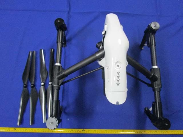
Click to zoom
Application Details
- Equipment Class
- DTS - Digital Transmission System
- Date of Grant
- Oct 30, 2014
- Application Purpose
- Original Equipment
- Date of Application
- Oct 30, 2014
- Equipment Note
- DJI Inspire 1
- Frequency Range
- 2406.50000000 - 2476.50000000
- Company
- SZ DJI TECHNOLOGY CO., LTD
- Country
- China
Documents & Files
Document Text
Text extracted from the exhibit documents filed with the FCC. Open a document above to read the original.
Users Manual
DJI Inspire 1 User Manual Compliance Information KCC Warning Message “해당무선설비는 운용 중 전파혼신 가능성이 있으므로 인명안전과 관련된 서비스는 할 수 없습니다.” “해당 무선설비는 운용 중 전파혼신 가능성이 있음” In the Box Check that all of the following items have been included in your package before use. If anything is missing, please contact your local dealer. Index Name Picture Qty. 1 DJI Inspire 1 1 2 Propeller 4 3 C1 1 4 Camera with gimbal 1 5 Smart Battery 1 6 Battery Charger 1 Introduction DJI Inspire 1 package includes aircraft, C1, gimbal, camera and DJI App. Flight control system is inside the aircraft, the built‐in camera has been integrated with gimbal. C1 and DJI App are used to control the aircraft, gimbal and camera. The HD video downlink and receiver have been integrated in the aircraft, which is used for HD video transmitter and control the aircraft. Features: ‐Equipped with retractable landing gear, and unobstructed 360 degree view from the camera is made possible by simply moving the landing gear out of sight. The maximum flight height of DJI Inspire 1 is **, the maximum distance is **. DJI Inspire 1 has a battery capacity of 6S, 4500mAh. When the battery is fully charged, it has a maximum run time of **. ‐ The camera is using a 21mm bugeye lens, which has low optical distortion and high resolution. Video output can be achieved at HD 4Kp30@60Mbps and it supports many kinds of filters. A high performance gimbal enables to obtain stable images even when the aircraft is fling in high speed. -Integrated the advanced flight controller of DJI, the DJI Inspire 1 has stable performance during flight. It can automatically fly back when the C1 signal was missed. The hover assistant enable the DJI Inspire 1 to hover stable without GPS. ‐ The HD video downlink has been integrated inside the aircraft, which is used with DJI App to display real time HD aerial image, aircraft data and camera data on the mobile device. In addition, it provides ground station function which allows users to plan the flight mission and enables aircraft to flight automatically. Flight safety In GPS mode, the aircraft can be positioned accurately and hover stably, and the return home function is available. (Orientation of aircraft is under control but it could not avoid obstructer automatically). Hover assistant makes aircraft hover stable without GPS (hover assistant can work properly below height of 5m, and the floor surface have pattern variations in good light conditions). Airc GL6 [1] A [2] M [3] S [4] N [5] R [6] T [7] B [8] S [9] P [10] [11] raft 58A Antenna Mounting Po Stick Neck Strap A RTH Button Transformati Battery Leve Status LED Power Button Camera Sett Playback Bu osition Attachment ion Switch el LEDs n tings Dial utton [1] [2] [3] [4] [5] [6] [7] [8] [9] [10] [11] [12] [13] Built‐in G Propeller Motor Front L E Landing Frame a r Gimbal DJI Sma r Micro‐US Rear LED Camera M Camera M Port Hover a s GPS r ED gear rm rt Battery SB Port D Micro‐USB P Micro‐SD C ssistant cam Port ard era [12] Shutter Button [13] Flight Mode Switch [14] Video Recording Button [15] Gimbal Dial [16] HDMI Port [17] Upgrade Port [18] CAN Port [19] USB Port [20] Handle Bar [21] Reserved Button [22] Power Source Port [23] Reserved Button Start 1. Watch the tutorial video Scan the QR code or click the link shown below to watch the tutorial video. Tutorial video http://www.dji.com/Inspire1/training 2. Download DJI App Search ʺDJI” on the App Store then follow instructions for iOS version. Search ʺDJIʺ on Google Play then follow instructions for Android version. Register your e‐mail address when using the app for the very first time. App Store Google Play 3. Ensure the smart battery\C1 and the mobile device are fully charged. Please charge the device if it has low battery level. Important: Please watch the tutorial and read the quick start guide fully before using your DJI Inspire 1. * For the best experience, install and use the DJI App on tablet. ** See Appendix for checking battery levels. Refer to user manual for charging。 DJI App There are four page of GUI: Camera, ground station, tool box and user center. [1] Present flight mode [2] GPS signal status [3] Aircraft status [4] RC settings [5] HD video downlink settings [6] Smart battery information [7] General settings [8] Photo format [9] Video format/Recording time [10] Shutter/Record switch [11] Shutter/Record [12] Play back [13] Camera settings [14] Ground station [15] Aircraft orientation/Height/Distance [16] Home point settings [17] Return home [18] Gimbal mode [19] Take off Camera GUI: For display the real time HD images and aircraft data, enable shutter and video recording. Ground Station: For display the map for setting flight mission. User Center: photograph and video synchronization, flight record, DJI Shop and account information. Preparing DJI Inspire 1 1. Mounting the Gimbal Step 1:Remove the Gimbal Cover and the Gimbal Clamp from the gimbal. Step 2:Turn the Gimbal Lock to the right (when you are facing the nose of the DJI Inspire 1) until it locks in place and you hear a clicking sound. Refer to the picture below for details: Step 3: Insert the gimbal into the Gimbal Lock. Ensure the white mark on the gimbal is aligned with the white mark on the left of the Gimbal Lock. Refer to the picture below for details: Step 4: With the gimbal in place, turn the Gimbal Lock to the left (when you are facing the nose of the DJI Inspire 1) until it locks in the position shown in the below. Now the gimbal is secured: 2. Attaching the Propellers Screw the propellers, clockwise for grey nuts and anti‐clockwise for black nuts, onto the four motors. Be sure to match the black propeller nuts with the black dot motors. Important:Make sure your smart flight battery and Micro‐SD care are inserted correctly. 3. Description of Aircraft Port (See the location on P) Micro‐USB Port: For connecting aircraft and PC Assistant to upgrade firmware. Camera Micro‐ USB Port: For connecting aircraft and PC to output the data to PC. Camera Micro‐SD Ca…
Text truncated - open the document above for the full version.
Cover Letter(s)
PERMANENT AND SHORT-TERM CONFIDENTIAL LIST Exhibit Description PERMANENT 1 Block Diagram 2 Circuit Description 3 Schematic SHORT-TERM 4 External and Internal Photos 5 Test-Setup Photos 6 User Manual SZ DJI TECHNOLOGY CO., LTD. Add:17th floor, West Wing, Skyworth Semiconductor Design Building NO.18 Gaoxin South 4th Ave, Nanshan, Shenzhen, Guangdong Tel: 0755- 26656677 Fax: 0755-86965903 Date: 2014-10-28 Federal Communications Commission Authorization and Evaluation Division 7435 Oakland Mills Road, Columbia, MD 21046 RE: Request of confidentiality for FCC ID: SS3-WM6101410 To Whom It May Concern: Pursuant to Sections 0.457 and 0.459 of the Commission’s Rules (CFR 47), and Section 552 (b) (4) of the Freedom of Information Act, SZ DJI TECHNOLOGY CO., LTD.hereby requests confidentiality and treatment of certain information accompanying this application. The materials contain trade secrets and proprietary information not customarily released to the public. The public disclosure of these matters might be harmful to the applicant and provide unjustified benefits to its competitors. We are also hereby request Short-Term Confidentiality for 180 days after the grant as outlined in Public Notice DA 04-1705. This provision will give SZ DJI TECHNOLOGY CO., LTD. temporary confidentiality of commercially sensitive information prior to product release. The requested Permanent and Short-Term Confidential exhibits are listed as follows: The applicant understands that pursuant to Rule 0.457, disclosure of this application and all accompanying documentations, where applicable, will not be made public before the date of the Grant for this application. Sincerely, Signature: Qian, Hongyu Engineer
External Photos
EXHIBIT B - EUT EXTERNAL PHOTOGRAPHS EUT – All View EUT – Top View EUT – Bottom View EUT – Side View EUT – Side View
ID Label/Location Info
EXHIBIT A - FCC ID LABELING AND LOCATION FCC ID Label Proposed FCC ID Label Location The label shown shall be permanently affixed at a conspicuous location on the device and be readily visible to the user at the time purchase (Labeling requirements per 2.925) Label Here
Internal Photos
EXHIBIT C - EUT INTERNAL PHOTOGRAPHS EUT – Uncover View EUT –Uncover View EUT – Uncover View EUT – Uncover View EUT – Uncover View EUT – Uncover View EUT – Uncover View EUT – Uncover View EUT – Motor Board Top View EUT – Motor Board Bottom View EUT – Sensor Unit Uncover View EUT – Sensor Unit Uncover View EUT – Sensor Board Top View EUT – Sensor Board Bottom View EUT – Power Connect Board Top View EUT – Power Connect Board Bottom View EUT – Battery Top View EUT – Battery Bottom View EUT – 2.4GHz Antenna View EUT – Camera Uncover View EUT – Camera Uncover View EUT – Camera Connect Board Top View EUT – Camera Connect Board Bottom View EUT – Camera Yan Connect Board Top View EUT – Camera Yan Connect Board Bottom View EUT – Camera Uncover View EUT – Camera Motor Board Top View EUT – Camera Motor Board Bottom View EUT – Camera Uncover View EUT – Camera Main Board Top View EUT – Camera Main Board Bottom View EUT – Camera Sensor Top View EUT – Camera Sensor Bottom View EUT – GPS Uncover View EUT – GPS Light Board Top View EUT – GPS Light Board Bottom View EUT – GPS Main Board Top View EUT – GPS Main Board Top Uncover View EUT – GPS Main Board Bottom View EUT – GPS RF Module View EUT – Uncover View EUT – Connect Board Top View EUT – Connect Board Bottom View EUT –Uncover View EUT – Uncover View EUT – RF Board Top View EUT – RF Board Bottom View EUT –RF Circuit View EUT – Main Board Top View EUT – Main Board Bottom View
Test Report
Note: This test report is prepared for the customer shown above and for the device described herein. It may not be duplicated or used in part without prior written consent from Bay Area Compliance Laboratories Corp. (Dongguan). This report is valid only with a valid digital signature. The digital signature may be available only under the Adobe software above version 7.0. FCC PART 15.247 TEST REPORT For SZ DJI TECHNOLOGY CO., LTD 17th floor, West Wing, Skyworth Semiconductor Design Building NO.18 Gaoxin South 4th Ave, Nanshan, Shenzhen, Guangdong, China Report Type: Original Report Product Type: DJI Inspire 1 Test Engineer: Allen Qiao Report Number: RDG140930010-00A Report Date: 2014-10-24 Reviewed By: Leon Chen RF Engineer Test Laboratory: Bay Area Compliance Laboratories Corp. (Dongguan) No.69 Pulongcun, Puxinhu Industrial Zone, Tangxia, Dongguan, Guangdong, China Tel: +86-769-86858888 Fax: +86-769-86858891 www.baclcorp.com.cn FCC ID: SS3-WM6101410 Bay Area Compliance Laboratories Corp. (Dongguan) Report No.: RDG140930010-00A FCC Part 15.247 Page 2 of 47 TABLE OF CONTENTS GENERAL INFORMATION.......................................................................................................................................4 PRODUCT DESCRIPTION FOR EQUIPMENT UNDER TEST (EUT) .....................................................................................4 OBJECTIVE...................................................................................................................................................................4 RELATED SUBMITTAL(S)/GRANT(S).............................................................................................................................4 TEST METHODOLOGY..................................................................................................................................................4 TEST FACILITY.............................................................................................................................................................4 SYSTEM TEST CONFIGURATION ..........................................................................................................................5 DESCRIPTION OF TEST CONFIGURATION......................................................................................................................5 EUT EXERCISE SOFTWARE..........................................................................................................................................5 EQUIPMENT MODIFICATIONS.......................................................................................................................................5 BLOCK DIAGRAM OF TEST SETUP................................................................................................................................5 SUMMARY OF TEST RESULTS...............................................................................................................................6 FCC §15.247 (i) & §1.1307 & §2.1091- MAXIMUM PERMISSIBLE EXPOSURE (MPE).........................................7 APPLICABLE STANDARD..............................................................................................................................................7 FCC §15.203 - ANTENNA REQUIREMENT.............................................................................................................8 APPLICABLE STANDARD..............................................................................................................................................8 ANTENNA CONNECTOR CONSTRUCTION......................................................................................................................8 FCC §15.209, §15.205 & §15.247(d) - SPURIOUS EMISSIONS...............................................................................9 APPLICABLE STANDARD..............................................................................................................................................9 MEASUREMENT UNCERTAINTY....................................................................................................................................9 EUT SETUP..................................................................................................................................................................9 EMI TEST RECEIVER & SPECTRUM ANALYZER SETUP..............................................................................................10 TEST PROCEDURE......................................................................................................................................................10 CORRECTED AMPLITUDE & MARGIN CALCULATION.................................................................................................11 TEST EQUIPMENT LIST AND DETAILS.........................................................................................................................11 TEST RESULTS SUMMARY..........................................................................................................................................11 TEST DATA................................................................................................................................................................11 FCC §15.247(a) (2) – 6dB BANDWIDTH..................................................................................................................19 APPLICABLE STANDARD............................................................................................................................................19 TEST PROCEDURE......................................................................................................................................................19 TEST EQUIPMENT LIST AND DETAILS.........................................................................................................................19 TEST DATA............................................................................…
Text truncated - open the document above for the full version.
Test Setup Photos
EXHIBIT D - TEST SETUP PHOTOGRAPHS Radiated Emission Below 1GHz View Radiated Emission Above 1GHz View
Contact Information
Applicant
Gary Zeng(PM)
Test Firm
Bay Area Compliance Laboratories Corp. (Dongguan)John Chan
[email protected]86-769-86858888
Technical Specifications
| # | Rule Parts | Frequency Range | Power Output |
|---|---|---|---|
| 1 | 15C | 2.41 GHz - 2.48 GHz | 255.00 mW |
Other Applications from SZ DJI TECHNOLOGY CO., LTD
SS3-T55A2510
Dec 19, 2025DJI AGRAS T55
Equipment Class
NII - Unlicensed National Information Infrastructure TXSS3-T100A2510
Dec 19, 2025DJI AGRAS T100S, DJI AGRAS T70S
Equipment Class
NII - Unlicensed National Information Infrastructure TXSS3-TKMI2507
Dec 19, 2025DJI RC Mini
Equipment Class
DTS - Digital Transmission SystemSS3-RD60B2510
Dec 18, 2025Fixed Millimeter Wave Radar
Equipment Class
FDS - Part 15 Field Disturbance SensorSS3-RD60A2510
Dec 18, 2025Rotational Active Phased Array Radar
Equipment Class
FDS - Part 15 Field Disturbance Sensor