SS5TH400TEMPTEMPERATURE SENSOR
MSI Sensors (ASIA) Ltd.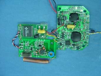
Click to zoom
Application Details
- Equipment Class
- DXX - Part 15 Low Power Communication Device Transmitter
- Date of Grant
- Mar 22, 2005
- Application Purpose
- Original Equipment
- Date of Application
- Mar 22, 2005
- Equipment Note
- TEMPERATURE SENSOR
- Frequency Range
- 433.72000000 - 434.12000000
- Company
- MSI Sensors (ASIA) Ltd.
- Country
- China
Documents & Files
Document Text
Text extracted from the exhibit documents filed with the FCC. Open a document above to read the original.
Users Manual
Page 19 MSI Sensors (ASIA) Ltd. Temperature Module FCC ID:SS5TH400TEMP Page 20 MSI Sensors (ASIA) Ltd. Temperature Module FCC ID:SS5TH400TEMP Page 21 MSI Sensors (ASIA) Ltd. Temperature Module FCC ID:SS5TH400TEMP Page 22 MSI Sensors (ASIA) Ltd. Temperature Module FCC ID:SS5TH400TEMP Page 23 MSI Sensors (ASIA) Ltd. Temperature Module FCC ID:SS5TH400TEMP Page 24 MSI Sensors (ASIA) Ltd. Temperature Module FCC ID:SS5TH400TEMP Page 25 MSI Sensors (ASIA) Ltd. Temperature Module FCC ID:SS5TH400TEMP Page 26 MSI Sensors (ASIA) Ltd. Temperature Module FCC ID:SS5TH400TEMP Page 27 MSI Sensors (ASIA) Ltd. Temperature Module FCC ID:SS5TH400TEMP Page 28 MSI Sensors (ASIA) Ltd. Temperature Module FCC ID:SS5TH400TEMP NOTE: THE MANUFACTURER IS NOT RESPONSIBLE FOR ANY RADIO OR TV INTERFERENCE CAUSED BY UNAUTHORIZED MODIFICATIONS TO THIS EQUIPMENT. SUCH MODIFICATIONS COULD VOID THE USER’S AUTHORITY TO OPERATE THE EQUIPMENT.
Block Diagram
Page 11 MSI Sensors (ASIA) Ltd. Temperature Module FCC ID:SS5TH400TEMP Block Diagram BLOCK DIAGRAM
Cover Letter(s)
TIMCO ENGINEERING INC. TCB & FCB 849 NW State Road 45 FCC Approvals Newberry, Florida 32669 Industry Canada Approvals http://www.timcoengr.com Notified Body for Europe 888.472.2424 F 352.472.2030 email: [email protected] August 24, 2005 MS ELSA WU AUDIX TECHNOLOGY (SHENZHEN) CO., LTD. 86-755-6639496 86-755-6632877 [email protected]; [email protected] SUBJECT: MSI SENSORS (ASIA) LTD. - FCC ID: SS5TH400TEMP REFERENCE: JOB 591CC5 Dear Ms. Wu: The FCC has audited this application for Certification. Please provide objective evidences of compliance with the following part 15 rules. The FCC can dismiss this application if answers are not provided by 9/3/05: 1. Part 15.231(a): Data transmission is allowed as long as the data is sent with a control signal, such as the type sent with traditional keyless entry transmitters. Transmission of live data alone is prohibited. Please describe the control signal in technical terms (i.e. number of bits and timing allocated for the control signal) before sending live data. 2. Part 15.231(a)(1): Please explain compliance with the following in the test report: A device manually activated shall employ a switch that will automatically deactivate the transmitter within 5 seconds. Does this device comply with this requirement? After a person steps away from the scale, does the transmitter stop transmitting within 5seconds? 3. Part 15.231(a)(2): Is this device automatically activated (i.e. transmitting without a person stepping on scale, etc.). If the answer is no, then include in the test report a statement that it is not automatically activated. Otherwise, please explain how the transmission will cease within 5 second after activation. 4. Part 15.231(a)(3): Is this device transmitting only when manually activated? If so, please include such statement in the test report. Otherwise, please explain compliance with the timing requirement of this section. 5. Part 15.231(c): Test report Section 4 - Please specify the Spectrum analyzer settings used to take the bandwidth plot. The RBW should be set to approximately 1% of the measured bandwidth, but in no case less than 1% of the measured bandwidth. RBWs greater than the 1% measured bandwidth are acceptable as long as the measured bandwidth complies with the limit. S:\TimcoOffice\ReportTemplate\Probonholdemail.doc Rev 25 June03 Sincerely, Bruno Clavier S:\TimcoOffice\ReportTemplate\Probonholdemail.doc Rev 25 June03
Cover Letter(s)
file:///U|/M/MSI/591CC5/oet%2022146/cust%20reply%2013%20oct%2005.txt From: TEI [[email protected]] Sent: Thursday, October 13, 2005 8:04 AM To: Eric Dobson Subject: FW: MSI SENSORS (ASIA) LTD. - FCC ID: SS5TH400TEMP -----Original Message----- From: susan [mailto:[email protected]] Sent: Wednesday, October 12, 2005 9:11 PM To: [email protected] Subject: MSI SENSORS (ASIA) LTD. - FCC ID: SS5TH400TEMP SUBJECT: MSI SENSORS (ASIA) LTD. - FCC ID: SS5TH400TEMP REFERENCE: JOB 591CC5 Gilbert: this device automatically activated (i.e. transmitting without a person stepping on scale, etc.). it transmitting will stop after continue 30ms, stop 2 minutes, then rework above steps. Best Regards! ¡@¡@¡@¡@¡@¡@¡@¡@-P §¡I susan [email protected] 2005-10-13 file:///U|/M/MSI/591CC5/oet%2022146/cust%20reply%2013%20oct%2005.txt10/14/2005 5:20:13 AM
Cover Letter(s)
Thank you for your email. Next time, please provide an answer for each question and keep the same numbering system (i.e. copy the question and provide a reply under each question) We have the following questions: 1. Please confirm that this device was filed according to 15.231(e) and NOT 15.231(a). 2. The operational description lists a ON time of 33ms with a silent period of 1 minute for automatic transmission. Your email reply states 30 ms and a silent period of 2 minutes. Please clarify the timing for this device. Please provide a plot. 3. The operational description lists a ON time of 510ms in normal use of the scale by a person. What is the silent period between transmissions in this case? Please explain compliance with the silent period requirement of part 15.231(e). 4. Page 3-5 (11/24 pdf): The RBW and VBW specified for Peak and Average are wrong for frequency above 1GHz. Please explain or revise accordingly the RBW and VBW for peak and average detector. 5. Part 15.231(c): Test report Section 4 - Please specify the Spectrum analyzer settings used to take the bandwidth plot. The RBW should be set to approximately 1% of the measured bandwidth, but in no case less than 1% of the measured bandwidth. RBWs greater than the 1% measured bandwidth are acceptable as long as the measured bandwidth complies with the limit. ~~~~~~~~~~~~~~~~~~~~~~~~~`` Best Regards, Bruno Clavier TIMCO ENGINEERING INC. 849 NW State Road 45 Newberry, Florida 32669 http://www.timcoengr.com 888.472.2424 F 352.472.2030 mailto:[email protected]
Cover Letter(s)
Sent: Thursday, December 15, 2005 8:20 AM To: Eric Dobson Subject: FW: FCC audit of application for MSI SENSORS (ASIA) LTD. - FCC ID: SS5TH400TEMP -----Original Message----- From: susan [mailto:[email protected]] Sent: Thursday, December 15, 2005 1:14 AM To: tei Cc: gilbert; rita Subject: Fw: FCC audit of application for MSI SENSORS (ASIA) LTD. - FCC ID: SS5TH400TEMP SUBJECT: MSI SENSORS (ASIA) LTD. FCC ID: SS5TH400TEMP REFERENCE: JOB 591CC5 Dear Sir: I am sorry answer your question now. I had answered a E-mail before about twenty days, yesterday I contact client for your quentions, client answer the device automatic transmission about 60ms with a silent period of 2 minutes. I am sorry for the operation description lists a on time of 510ms in normal us of the scale by a person, and this informaion is wrong.I had modification the 731 form/OpDes/Usermanul and Test report of this application, and send its by E-mail to you today, pls refer the attachment. If you have any questions feel free to contact me .Thanks! susan [email protected] 2005-12-15
External Photos
Page 6 MSI Sensors (ASIA) Ltd. Temperature Module FCC ID:SS5TH400TEMP Photographs Figure 1 General Appearance Figure 2 General Appearance Label Location
ID Label/Location Info
Page 6 MSI Sensors (ASIA) Ltd. Temperature Module FCC ID:SS5TH400TEMP Photographs Figure 1 General Appearance Figure 2 General Appearance Label Location
ID Label/Location Info
Page 4 MSI Sensors (ASIA) Ltd. Temperature Module FCC ID:SS5TH400TEMP Label Drawing Please refer Exhibit 2 Figure 2 for Label Placement Location FCC ID: SS5TH400TEMP Model Number: TH400 Accessory This device complies with Part 15 of the FCC Rules. Operation is subject to the following two conditions: (1) this device may not cause harmful interference, and (2) this device must accept any interference received, including interference that may cause undesired operation.
Internal Photos
Page 7 MSI Sensors (ASIA) Ltd. Temperature Module FCC ID:SS5TH400TEMP Figure 3 Main Board, Component Side Figure 4 Main Board, Component Side Page 8 MSI Sensors (ASIA) Ltd. Temperature Module FCC ID:SS5TH400TEMP Figure 5 Main Board, Component Side
Operational Description
Page 17 MSI Sensors (ASIA) Ltd. Temperature Module FCC ID:SS5TH400TEMP
Schematics
Page 13 MSI Sensors (ASIA) Ltd. Temperature Module FCC ID:SS5TH400TEMP Page 14 MSI Sensors (ASIA) Ltd. Temperature Module FCC ID:SS5TH400TEMP
Test Report
FCC ID:SS5TH400TEMP Audix Technology (Shenzhen) Co., Ltd. Report No. ACS-F05068 APPLICATION FOR CERTIFICATION On Behalf of MSI Sensors (ASIA) Ltd. Temperature Module Model Number: TH400 Accessory Prepared for : MSI Sensors (ASIA) Ltd. 4A, F1.6, Tian’an Cyber Park, Shenzhen. Prepared By : Audix Technology (Shenzhen) Co., Ltd. No. 6, Ke Feng Rd., 52 Block, Shenzhen Science & Industrial Park, Nantou, Shenzhen, Guangdong, China Tel: (0755) 26639496 Report Number : ACS-F05068 Date of Test : Mar. 07, 2005 Date of Report : Mar.15, 2005 FCC ID:SS5TH400TEMP Audix Technology (Shenzhen) Co., Ltd. Report No. ACS-F05068 TABLE OF CONTENTS Description Page Test Report Declaration 1. GENERAL INFORMATION .................................................................................................... 1-1 1.1. Description of Device (EUT) .............................................................................................................1-1 1.2. Test Facility........................................................................................................................................1-2 1.3. Test Uncertainty .................................................................................................................................1-2 2. POWER LINE CONDUCTED EMISSION TEST ................................................................. 2-1 3. RADIATED EMISSION TEST................................................................................................. 3-1 3.1. Test Equipment...................................................................................................................................3-1 3.2. Block Diagram of Test Setup .............................................................................................................3-1 3.3. Radiated Emission Limit ( FCC Part 15.231(e) ) ..............................................................................3-2 3.4. EUT Configuration on Test................................................................................................................3-2 3.5. Operating Condition of EUT ..............................................................................................................3-3 3.6. Test Procedure....................................................................................................................................3-3 3.7. Radiated Emission Test Results .........................................................................................................3-4 4. BANDWIDTH TEST..................................................................................................................4-6 4.1. Test Equipment...................................................................................................................................4-6 4.2. Test Standard......................................................................................................................................4-6 4.3. Bandwidth Limit: (0.25%*433.90MHz=1.08MHz)...........................................................................4-6 4.4. Test Procedure....................................................................................................................................4-6 5. PHOTOGRAPH.......................................................................................................................... 5-1 5.1. Photos of Radiated Emission Test (In Anechoic Chamber)...............................................................5-1 APPENDIX I (5 pages) FCC ID:SS5TH400TEMP Audix Technology (Shenzhen) Co., Ltd. Report No. ACS-F05068 TEST REPORT DECLARATION Applicant : MSI Sensors (ASIA) Ltd. Manufacturer : MSI Sensors (ASIA) Ltd. EUT Description : Temperature Module (A) MODEL NO. : TH400 Accessory (B) SERIAL NO. : F2005031501 (C) POWER SUPPLY : Battery DC 4.5V Test Procedure Used: FCC Rules and Regulations Part 15 Subpart C Apr. 2004. The device described above is tested by Audix Technology (Shenzhen) Co., Ltd. to determine the maximum emission levels emanating from the device. The maximum emission levels are compared to the FCC Part 15 Subpart C limits for radiated and conducted emissions. The test results are contained in this test report and Audix Technology (Shenzhen) Co., Ltd. is assumed full responsibility for the accuracy and completeness of tests. Also, this report shows that EUT is technically compliant with FCC requirements. This report applies to above tested sample only. This report shall not be reproduced in part without written approval of Audix Technology (Shenzhen) Co., Ltd. Date of Test : Mar. 07, 2005 Prepared by : Reviewer : Approved & Authorized Signer : Name of the Representative of the Responsible Party : Signature : FCC ID:SS5TH400TEMP Page Audix Technology (Shenzhen) Co., Ltd. Report No. ACS-F05068 1-1 1. GENERAL INFORMATION 1.1. Description of Device (EUT) Description : Temperature Module Model Number : TH400 Accessory Applicant : MSI Sensors (ASIA) Ltd. 4A, F1.6, Tian’an Cyber Park, Shenzhen. Manufacturer : MSI Sensors (ASIA) Ltd. 4A, F1.6, Tian’an Cyber Park, Shenzhen. Date of Test : Mar. 07, 2005 FCC ID:SS5TH400TEMP Page Audix Technology (Shenzhen) Co., Ltd. Report No. ACS-F05068 1-2 1.2. Test Facility Site Description 3m Anechoic Chamber : Certificated by FCC, USA Registration Number: 90454 Aug. 15, 2003 3m & 10m Anechoic Chamber : Certificated by FCC, USA Registration Number: 794232 Mar. 15, 2004 EMC Lab. : Certificated by DATech, German Registration Number: DAT-P-091/99-01 Feb. 02, 2004 Certificated by NVLAP, USA NVLAP Code: 200372-0 Mar. 31, 2004 Certificated by Nemko, Norway Aut. No.: ELA135 April. 22, 2004 Certificated by Industry Canada Registration Number: IC 5183 Jul. 28, 2004 Name of Firm : Audix Technology (Shenzhen) Co., Ltd. Site Location : No. 6, Ke Feng Rd., 52 Block, Shenzhen Science & Industrial Park, Nantou, Shenzhen, Guangdong, China 1.3. Test Uncertainty No. Item Uncertainty Remark 1. Uncertainty for Conducted Emission Test …
Text truncated - open the document above for the full version.
Test Setup Photos
FCC ID:SS5TH400TEMP Audix Technology (Shenzhen) Co., Ltd. Report No. ACS-F05068 5. PHOTOGRAPH 5.1. Photos of Radiated Emission Test (In Anechoic Chamber)
Contact Information
Applicant
James Zhan(Engineer)
Test Firm
Audix Technology (Shenzhen) Co.Smart Tsai
Technical Specifications
| # | Rule Parts | Frequency Range | Power Output |
|---|---|---|---|
| 1 | 15C | 433.72 MHz - 434.12 MHz | - |
Other Applications from MSI Sensors (ASIA) Ltd.
SS5DDS330
Jun 12, 2005DEER SCALE
Equipment Class
DXX - Part 15 Low Power Communication Device Transmitter
SS5TH400SCALE
Mar 22, 2005RF BODYFAT SCALE
Equipment Class
DXX - Part 15 Low Power Communication Device Transmitter
SS5TH8XSCALE
Mar 22, 2005LOW POWER COMMUNICATION DEVICE TRANSMITTER
Equipment Class
DXX - Part 15 Low Power Communication Device Transmitter