Text extracted from the exhibit documents filed with the FCC. Open a document above to read the original.
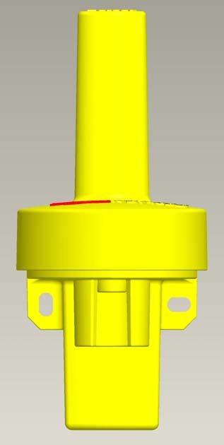
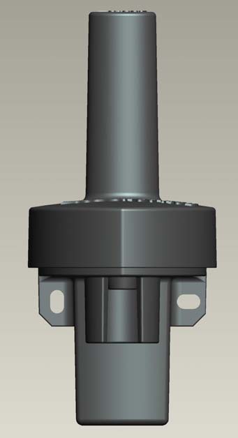
PAGE 1 OF 2 HERSEY METERS PRODUCT GUIDE FOR THE AMR TRANSMITTER OVERVIEW This document is intended to assist professional installers with Hersey Meters’ AMR transmitters. It provides instructions on how to successfully connect, operate, and troubleshoot the transmitters. Hersey’s remote meter reading transmitters were designed with an “easy to install approach” for utilities. The SSDHOTRODMETALV1 or SSDHOTRODPLASTCV1 allow the utility to receive data from any Hersey water meter equipped with a Translator register. The transmitter collects data from the register and transmits it via radio frequency (RF) to be collected by a mobile receiver . PRODUCT FEATURES • The thermoplastic housing design reduces material and helps eliminate air space within the transmitter. (Figures 1 and 2) • Mounting features include two holes for wall installation and a 1/2 inch female PVC pipe fitting for easy pit installation. (Figure 2) • The transmitter units are molded from yellow or gray plastic so that the high power and low power units are easily distinguishable. The high power unit should only be used within a metal meter box. (Figures 1 and 2) • A quarter wavelength whip antennae is utilized due to the small amount of power it consumes. • Two AA Lithium batteries are utilized that will transmit readings every 4 seconds for a calculated battery life of over 10 years. • The electronic design utilizes the latest in RF microchip technology which reduces cost and increases reliability when compared to older RF designs. • In order to protect the AMR transmitter from moisture ingress, the design incorporates the use of thermoplastic injection molded housings, rubber seals, a potting compound that completely incases the internal electronics and a coated circuit board which provides the final barrier of protection. Internal wire strain relief has been built into the housing to protect the wire connections against damage. Please note that this does not mean meters or registers can be carried while supported only by the AMR transmitter or wiring. CONNECTING AND OPERATING THE HERSEY AMR TRANSMITTER Figure 1 HIGH POWER Figure 2 LOW POWER PVC Installation Slot Wall Installation PAGE 2 OF 2 The AMR transmitter is preprogrammed prior to being attached to the meter. All pit set units come with either 5’ or 25’ of wire attached and potted at the factory as specified. If a retro fit is required, the wires should be spliced to the existing wires coming from the register. Wire the red to red, green to green, and black to black wires using 3M UY2 Scotchlok splices with the E-9Y application tool. (Figure 3) If a new wall unit is being installed it can be directly mounted to any surface by using the holes shown in Figure 2 and the appropriate screws. New pit installations can use the mounting method described above or a ½” PVC pipe can be used in conjunction with the PVC Installation Slot shown in Figure 2. This feature allows for quick easy installation without the use of zip ties, wraps, tape, or adhesives. Two solid stops were included in the PVC Installation Slot in order to prevent the wire from being pinched when the PVC pipe is installed. For best performance the top of the transmitter should be placed approximately 6 inches below the pit lid. Please note that the AMR transmitter will only support the Hersey Translator register and will not work with Hersey’s ER, pulse registers. A TRU-Read remote display can be used in conjunction with the Translator register and AMR transmitter for visual remote readings if desired. Refer to TRU-Read installation instructions below to attach both devices. When wiring the TRU-Read to the Translator you must connect the red wire to the red terminal, the green to green, and the black to black. (Figure 4) To attach the AMR transmitter, wire the red wire to terminal #1, the green wire to #2, and the black wire to terminal #3 on the TRU-Read. (Figure 4) Once the transmitter is attached it will begin sending out data automatically. Please note that Hersey Meters’ AMR transmitter and TRU-Read should never be disassembled or user serviced. AMR TRANSMITTER TROUBLE SHOOTING PROBLEM POSSIBLE CAUSE POOR RANGE CHECK ORIENTATION OF THE HOT ROD ANTENNAE CHECK THE RECEIVER ANTENNAE CHECK FOR INTERFERENCE NOT TRANSMITTING CORRECT DATA CHECK WIRING CONNECTIONS CHECK WIRES FOR SHORT CHECK FOR INTERFERENCE CHECK DISTANCE TO RECEIVER CHECK TRANSLATOR STATUS NOT TRANSMITTING CHECK POWER ON AMR TRANSMITTER FCC INFORMATION The AMR transmitters operate in the license exempt 902 MHz to 928 MHz ISM band and are certified for operation in the US under FCC Part 15. The FCC ID numbers for the high power and low power versions are SSDHOTRODMETALV1 and SSDHOTRODPLASTCV1. Information pertaining to their certification can be found on the web at WWW.FCC.GOV . Figure 4 Figure 3
Report Number: 30462511.001 Page 1 of 37 EUT: Hot Rod Plastic (Low Power) Model: HOTRODPLASTCV1 33_EME/I 01/29/2001 FCCID: SSDHOTRODPLASTCV1 Emissions Test Report EUT Name: Hot Rod Plastic (Low Power) EUT Model: HOTRODPLASTCV1 FCC Title 47, Part 15, Subpart C Prepared for: Scott Linkel Hersey Meters 10210 Statesville Blvd. Cleveland NC 27013 Tel: 704-278-2221 Fax: 704-278-9617 Prepared by: TUV Rheinland of North America 762 Park Avenue Youngsville, NC 27596 Tel: (919) 554-3668 Fax: (919) 554-3542 http://www.tuv.com/ Report/Issue Date: 28 July 2005 Report Number: 30462511.001 Statement of Compliance Report Number: 30462511.001 Page 2 of 37 EUT: Hot Rod Plastic (Low Power) Model: HOTRODPLASTCV1 33_EME/I 01/29/2001 FCCID: SSDHOTRODPLASTCV1 Manufacturer: Hersey Meters 10210 Statesville Blvd. Cleveland NC 27013 704-278-2221 Requester / Applicant: Scott Linkel Name of Equipment: Hot Rod Plastic (Low Power) Model No. HOTRODPLASTCV1 Type of Equipment: RF Transmitter Class of Equipment: FCC Part 15.249 Application of Regulations: FCC Title 47, Part 15, Subpart C Test Dates: 11 November 2004 - 17 November 2004 Guidance Documents: Emissions: FCC 47 CFR Part 15 Test Methods: Emissions: FCC 47 Part 15, ANSI C63.4:2003 The electromagnetic compatibility test and documented data described in this report has been performed and recorded by TUV Rheinland of North America, in accordance with the standards and procedures listed herein. As the responsible authorized agent of the EMC laboratory, I hereby declare that a sample of one, of the equipment described above, has been shown to be compliant with the EMC requirements of the stated regulations and standards based on these results. If any special accessories and/or modifications were required for compliance, they are listed in the Executive Summary of this report. This report must not be used to claim product endorsement by NVLAP or any agency of the U.S. Government. This report contains data that are not covered by NVLAP accreditation. This report shall not be reproduced except in full, without the written authorization of the laboratory. 28 July 2005 NVLAP Signatory Date Table of Contents Report Number: 30462511.001 Page 3 of 37 EUT: Hot Rod Plastic (Low Power) Model: HOTRODPLASTCV1 33_EME/I 01/29/2001 FCCID: SSDHOTRODPLASTCV1 1 EXECUTIVE SUMMARY................................................................................................................. 4 1.1 SCOPE............................................................................................................................................ 4 1.2 PURPOSE........................................................................................................................................ 4 1.3 SUMMARY OF TEST RESULTS........................................................................................................ 4 1.4 SPECIAL ACCESSORIES.................................................................................................................. 4 1.5 EQUIPMENT MODIFICATIONS........................................................................................................ 4 2 LABORATORY INFORMATION ................................................................................................... 5 2.1 ACCREDITATIONS & ENDORSEMENTS.......................................................................................... 5 2.2 TEST FACILITIES............................................................................................................................ 5 2.3 MEASUREMENT UNCERTAINTY..................................................................................................... 6 2.4 CALIBRATION TRACEABILITY....................................................................................................... 6 3 PRODUCT INFORMATION ............................................................................................................7 3.1 PRODUCT DESCRIPTION.............................................................................................................. 13 3.2 EQUIPMENT CONFIGURATION..................................................................................................... 13 3.3 OPERATION MODE...................................................................................................................... 14 4 EMISSIONS ...................................................................................................................................... 14 4.1 RADIATED EMISSIONS................................................................................................................. 14 4.2 CONDUCTED EMISSIONS............................................................................................................. 34 4.3 BAND EDGE COMPLIANCE FOR FCC PART 15.209 AND 15.249 .................................................. 34 5 TEST EQUIPMENT USE LIST ...................................................................................................... 37 6 EMC TEST PLAN ............................................................................................................................ 37 TUV Rheinland of North America Scope 762 Park Ave., Youngsville, NC 27596 Tel: (919) 554-3668, Fax: (919) 554-3542 Report Number: 30462511.001 Page 4 of 37 EUT: Hot Rod Plastic (Low Power) Model: HOTRODPLASTCV1 33_EME/I 01/29/2001 FCCID: SSDHOTRODPLASTCV1 1 Executive Summary 1.1 Scope This report is intended to document the status of conformance with the requirements of the FCC Title 47, Part 15, Subpart C based on the results of testing performed on 11 November 2004 - 17 November 2004 on the Hot Rod Plastic (Low Power) Model No. HOTRODPLASTCV1 manufactured by Hersey Meters. This report only applies to the specific samples tested under the stated test conditions. It is the responsibility of the manufacturer to assure that additional production units of this model are manufactured with identical or EMI equivalent electrical and…
Text truncated - open the document above for the full version.
10210 STATESVILLE BLVD. · CLEVELAND, North Carolina · United States
| # | Rule Parts | Frequency Range | Power Output |
|---|---|---|---|
| 1 | 15C | 905 MHz - 925 MHz | - |

AMR Transmitter
Equipment Class
DXX - Part 15 Low Power Communication Device Transmitter