ST2-2X71YAsset/Patient/Temperature Tag IT-71X/IT-72X
Centrak, Inc.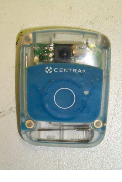
Click to zoom
Application Details
- Equipment Class
- DXT - Part 15 Low Power Transceiver, Rx Verified
- Date of Grant
- Dec 16, 2010
- Application Purpose
- Original Equipment
- Date of Application
- Dec 15, 2010
- Equipment Note
- Asset/Patient/Temperature Tag IT-71X/IT-72X
- Frequency Range
- 904.00000000 - 926.00000000
- Company
- Centrak, Inc.
- Country
- United States
Documents & Files
Document Text
Text extracted from the exhibit documents filed with the FCC. Open a document above to read the original.
Users Manual
InTouch Care User Manual Introduction InTouch Care is an Active RFID tracking system. The system is comprised of four basic elements: 1. TAGS – The TAGs are battery operated and are comprised of an RF Transceiver and a few peripheral components. The TAGs are small devices with about 1” X 2” foot print. They are typically attached to assets or people that need to be tracked. 2. Spiders – The Spiders are also battery operated and are equipped with similar to the TAG RF transceiver and other peripheral components. Unlike TAGs, Spiders are not mobile. They are typically attached to either ceilings or walls. Their function is to improve the localization capability of the system. 3. STARs – The STARs are operated either using an external power supply or a POE power supply within the device. STARs are also equipped with essentially identical RF section to both the TAGs and the Spiders. The STARs are also equipped with a LAN chip for communication with the server. 4. Server – The servers can be either local or can be connected directly to any Internet server. The Servers are in direct communication with the STARs. InTouch RFID Network high level architecture looks as follows: Server TAG STAR Spider Figure 1: InTouch Network Architecture STAR Installation and Operation Installation Stars should be installed as high as possible. It is preferred to attach them to the ceiling upside down such that the antennas point downward. The antennas should be positioned at 90 degrees to each other and perpendicular to each other. Stars can be fed through one of two methods: 1. Power Over Ethernet (POE) or 2. External 3.3 volts power supply. The STAR must be connected to the LOCAL AREA Network (LAN) which must be connected to InTouch Server. Operation The STAR communicates with all InTouch Components and is responsible to communicate information it receives to and from InTouch server. InTouch network can support up to 128 STARs Maintenance STAR malfunction is immediately sensed by the InTouch Server. The Network needs to be tested for before it is determined that the SART fails. In case, a STAR malfunctions it should be replaced with one in inventory. FCC NOTICE: This equipment has been tested and found to comply with the limits for a Class B digital device, pursuant to Part 15 of the FCC Rules. These limits are designed to provide reasonable protection against harmful interference in a residential installation. This equipment generates, uses and can radiate radio frequency energy and, if not installed and used in accordance with the instructions, may cause harmful interference to radio communications. If this equipment does cause harmful interference to radio or television reception, which can be determined by turning the equipment off and on, the user is encouraged to try to correct the interference by one or more of the following measures: • Reorient or relocate the receiving antenna. • Increase the separation between the equipment and the receiver. • Consult the dealer or an experienced radio/TV technician for help. • The carrier frequency is 904MHz – 926MHz. • The RF output power (or field strength and measurement distance) is less than one milliwatt. TAG Operation Installation In order to initiate a TAG the user must install a battery in the TAG. The preferred battery is CR 2335 that is enclosed in the TAG package. Other alternatives are CR2330 and CR2032. Both of the alternate batteries need a plastic shim that is included in the package. There is no on/off button on the TAG and it will start operation as soon as the battery is inserted. Also enclose in a pack of 10 TAGs a special tool to open and close the battery door. Operation There are five buttons on the TAG: The three buttons on top are used to signal the server a push button. The meaning of each button is programmable by the user on the PC level. There are two buttons on the bottom. One is a theft detection button. When the TAG is affixed to an asset the button is pressed in. If would be thief tries to remove the TAG from the asset the button is released and a message is sent immediately to the server. The second button is a reset button that allows a restart of the TAG in case, the TAG stops operation due to shock or a voltage spike. Maintenance The batteries last about four years. The replacement process follows the same instructions to install batteries. FCC NOTICE: This equipment has been tested and found to comply with the limits for a Class B digital device, pursuant to Part 15 of the FCC Rules. These limits are designed to provide reasonable protection against harmful interference in a residential installation. This equipment generates, uses and can radiate radio frequency energy and, if not installed and used in accordance with the instructions, may cause harmful interference to radio communications. If this equipment does cause harmful interference to radio or television reception, which can be determined by turning the equipment off and on, the user is encouraged to try to correct the interference by one or more of the following measures: • Reorient or relocate the receiving antenna. • Increase the separation between the equipment and the receiver. • Consult the dealer or an experienced radio/TV technician for help. • The carrier frequency is 904MHz – 926MHz. • The RF output power (or field strength and measurement distance) is less than one milliwatt. Spider Installation and Operation Installation Spiders, like STARs should be installed as high as possible. It is preferred to attach them to the ceiling upside down such that the antennas point downward. The antennas should be positioned at 90 degrees to each other and perpendicular to each other. Spiders are battery operated by 6 D-Cell batteries The Spiders communicate with the STARs wirelessly, so no wiring is needed. Once the batteries are inserted, the on/off button should be moved to the on position. No more operations are needed to set the Spiders. Operation The Spider communicate…
Text truncated - open the document above for the full version.
Cover Letter(s)
207 Penns Trail, Newtown PA 18940 i Tel 215.860.2928 i Fax 215.359.0659 i www.centrak.com Date: November 16, 2010 FCC and IC Confidentiality Request In accordance with 0.459 & 0.457 of CFR 47, please, accept this letter as an official request to have the following kept as confidential for the reference IDs: IC:6012A-2X71Y, IC:6012A-2X32Y, FCC ID:ST2-2X71Y and FCC ID:ST2-2X32Y. The information provided is for the sole purpose of inclusion as exhibits in the Application for Certificate of the IC IDs stated above: We ask to keep confidential the following Tag (model # IT-713,IT-72 3 etc.), and Virtual Wall (model # IT-323, IT-321) documents: y Schematics y Block diagram y Operational description Sincerely, Israel Amir, CTO CenTrak, Inc. 207 Penns Trail Newtown, PA 18940 Tel 215-860-2928
Cover Letter(s)
207 Penns Trail, Newtown PA 18940 i Tel 215.860.2928 i Fax 215.359.0659 i www.centrak.com Date: 9/16/2010 Compliance Certification Services Certification Division 561F Monterey Road Morgan Hill, CA 95037 To whom it may concern: We, the undersigned, hereby authorize Advanced Compliance Laboratory, Inc., to act on our behalf in all manners relating to application for equipment authorization, including signing of all documents relating to these matters. Any and all acts carried out by Advanced Compliance Laboratory, Inc. on our behalf shall have the same effect as acts of our own. We, the undersigned, hereby certify that we are not subject to a denial of federal benefits, that includes FCC benefits, pursuant to Section 5301 of the Anti-Drug Abuse Act of 1988, 21 U.S.C. 853(a). In authorizing Advanced Compliance Laboratory, Inc. as our agent, we still recognize that we are responsible to: • comply with the relevant provisions of the certification program; • make all necessary arrangements for the conduct of the evaluation, including provision for examining documentation and access to all areas, records (including internal audit reports) and personnel for the purposes of evaluation (e.g. testing, inspection, assessment, surveillance, reassessment) and resolution of complaints; • make claims regarding certification only in respect of the scope for which certification has been granted; • do not use our product certification in such a manner as to bring the Certification Division into disrepute and not make any statement regarding our product certification which the Certification Division may consider misleading or unauthorized; • upon suspension or cancellation of certification, discontinue use of all advertising matter that contains any reference thereto and return any certification documents as required by the Certification Division; use certification only to indicate the products are certified as being in conformity with specified standards; • endeavor to ensure that no certificate or report nor any part thereof is used in a misleading manner; • ensure that any reference to our product certification in communication media such as documents, brochures or advertising, complies with the requirements of the Certification Division; • keep a record of all complaints made known to the us relating to the product’s compliance with requirements of the relevant standard and to make these records available to the Certification Division when requested; • take appropriate action with respect to such complaints and any deficiencies found in products or services that affect compliance with the requirements for certification; September 16, 2010 z Page 2 • document the actions taken This authorization is valid until further written notice from the applicant. Sincerely Yours, Printed Name: Israel Amir Title: CTO Company: Remote Play, Inc.
External Photos
FCC ID: ST2-2X71Y ——————————————————————————————————————————————— Advanced Compliance Lab, 6 Randolph Way, Hillsborough, NJ 08844 Tel: (908) 927-9288 Fax: (908) 927- 0728 22 7.1 Front View FCC ID: ST2-2X71Y ——————————————————————————————————————————————— Advanced Compliance Lab, 6 Randolph Way, Hillsborough, NJ 08844 Tel: (908) 927-9288 Fax: (908) 927- 0728 23 7.2 Back View
ID Label/Location Info
FCC ID: ST2-2X71Y ——————————————————————————————————————————————— Advanced Compliance Lab, 6 Randolph Way, Hillsborough, NJ 08844 Tel: (908) 927-9288 Fax: (908) 927- 0728 9 2. PRODUCT LABELING Figure 2.1 FCC ID Label Figure 2.2 Location of Label on the Side of EUT Figure 2.2 FCC Label Location FCC ID: ST2-2X71Y This device complies with part 15 of the FCC Rules. Operating is subject to the following two conditions: (1) This device may not cause harmful interference, and (2) this device must accept any interference received, including interference that may cause undesired operation. Figure 2.1 FCC ID Label (Only FCC ID shown on EUT) FCC Label
Test Report
ELECTROMAGNETIC EMISSION COMPLIANCE REPORT of ASSET/PATIENT/TEMPERATURE TAG MODEL: IT-711, IT-713, IT-714, IT-715, IT-721, IT-723, IT-724, IT-325 FCC ID: ST2-2X71Y November 03, 2010 This report concerns (check one): Original grant x Class II change Equipment type: Low Power Intentional Radiator Deferred grant requested per 47 CF 0.457(d)(1)(ii)? yes no x If yes, defer until: (date) Company agrees to notify the Commission by (date) of the intended date of announcement of the product so that the grant can be issued on that date. Transition Rules Request per 15.37? yes no x If no, assumed Part 15, Subpart B for unintentional radiators - the new 47 CFR [10-1-90 Edition] provision. Report prepared for: REMOTE PLAY, INC. Report prepared by: Advanced Compliance Lab Report number: 0048-101019-01-FCC Lab Code: 200101 The test result in this report IS supported and covered by the NVLAP accreditation 6 Randolph Way Hillsborough, NJ 08844 Tel: (908) 927 9288 Fax: (908) 927 0728 Advanced Compliance Laboratory FCC ID: ST2-2X71Y ——————————————————————————————————————————————— Advanced Compliance Lab, 6 Randolph Way, Hillsborough, NJ 08844 Tel: (908) 927-9288 Fax: (908) 927- 0728 2 Table of Contents Report Cover Page .................................................................................................... 1 Table of Contents ...................................................................................................... 2 Figures ....................................................................................................................... 3 1. GENERAL INFORMATION ............................................................................... 4 1.1 Verification of Compliance ...................................................................... 4 1.2 Equipment Modifications ........................................................................ 5 1.3 Product Information ................................................................................ 6 1.4 Test Methodology..................................................................................... 6 1.5 Test Facility .............................................................................................. 6 1.6 Test Equipment ........................................................................................ 6 1.7 Statement of the Document Use............................................................... 7 2. PRODUCT LABELING........................................................................................ 8 3. SYSTEM TEST CONFIGURATION................................................................... 9 3.1 Justification .............................................................................................. 9 3.2 Special Accessories ................................................................................... 9 3.3 Configuration of Tested System .............................................................. 9 4. SYSTEM SCHEMATICS ..................................................................................... 12 5. RADIATED EMISSION DATA........................................................................... 13 5.1 Field Strength Calculation....................................................................... 13 5.2 Test Methods and Conditions.................................................................. 13 5.3 Test Data .................................................................................................. 13 6. EUT RECEIVING MODE VERIFICATION ...................................................... 18 7. PHOTOS OF TESTED EUT................................................................................. 19 FCC ID: ST2-2X71Y ——————————————————————————————————————————————— Advanced Compliance Lab, 6 Randolph Way, Hillsborough, NJ 08844 Tel: (908) 927-9288 Fax: (908) 927- 0728 3 Figures Figure 2.1 FCC ID Label........................................................................................... 8 Figure 2.2 Location of Label on Back of the EUT.................................................... 8 Figure 3.1 Radiated Test Setup, Position 1 .............................................................. 10 Figure 3.2 Radiated Test Setup, Position 2 .............................................................. 10 Figure 3.3 Radiated Test Setup, Position 3 .............................................................. 11 Figure 4.1 EUT Schematics ....................................................................................... 12 Figure 7.1 Front View ............................................................................................... 20 Figure 7.2 Back View ................................................................................................ 21 Figure 7.3 Inside View............................................................................................... 22 Figure 7.4 PCB Component View............................................................................. 23 Figure 7.5 PCB Foil View......................................................................................... 24 FCC ID: ST2-2X71Y ——————————————————————————————————————————————— Advanced Compliance Lab, 6 Randolph Way, Hillsborough, NJ 08844 Tel: (908) 927-9288 Fax: (908) 927- 0728 4 1. GENERAL INFORMATION 1.1 Verification of Compliance EUT: ASSET/PATIENT/TEMPERATURE TAG Model: IT-711, IT-713, IT-714, IT-715, IT-721, IT-723, IT-724, IT-325 Applicant: REMOTE PLAY, INC. Test Type: FCC Part 15C CERTIFICATION Result: PASS Tested by: ADVANCED COMPLIANCE LABORATORY Test Date: October 19 - November 03, 2010 Report Number: 0048-101019-01-FCC The above equipment was tested by Compliance Laboratory, Advanced Technologies, Inc. for compliance with the requirement set forth in the FCC rules and regulations Part 15 subpart C. This said equipment in the configuration described in the report, shows the maximum emission levels emanating from equipment are within the compliance requ…
Text truncated - open the document above for the full version.
Test Setup Photos
FCC ID: ST2-2X71Y ——————————————————————————————————————————————— Advanced Compliance Lab, 6 Randolph Way, Hillsborough, NJ 08844 Tel: (908) 927-9288 Fax: (908) 927- 0728 12 Figure 3.1 Radiated Test Setup, position 1 Figure 3.2 Radiated Test Setup, position 2 FCC ID: ST2-2X71Y ——————————————————————————————————————————————— Advanced Compliance Lab, 6 Randolph Way, Hillsborough, NJ 08844 Tel: (908) 927-9288 Fax: (908) 927- 0728 13 Figure 3.3 Radiated Test Setup, position 3
Contact Information
Applicant
Sherre Staves(VP)
Test Firm
Advanced Compliance LaboratoryWei Li
Technical Specifications
| # | Rule Parts | Frequency Range | Power Output |
|---|---|---|---|
| 1 | 15C | 904 MHz - 926 MHz | - |
Other Applications from Centrak, Inc.
ST2-IT7210
Feb 13, 2026Safety 2.0 Bracelet
Equipment Class
DXX - Part 15 Low Power Communication Device Transmitter
ST2-CTHSB760
Mar 17, 2024BLE MultiMode Badge
Equipment Class
DTS - Digital Transmission System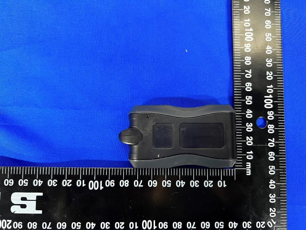
ST2-5MDT000371
Apr 06, 2022Man Down
Equipment Class
DTS - Digital Transmission System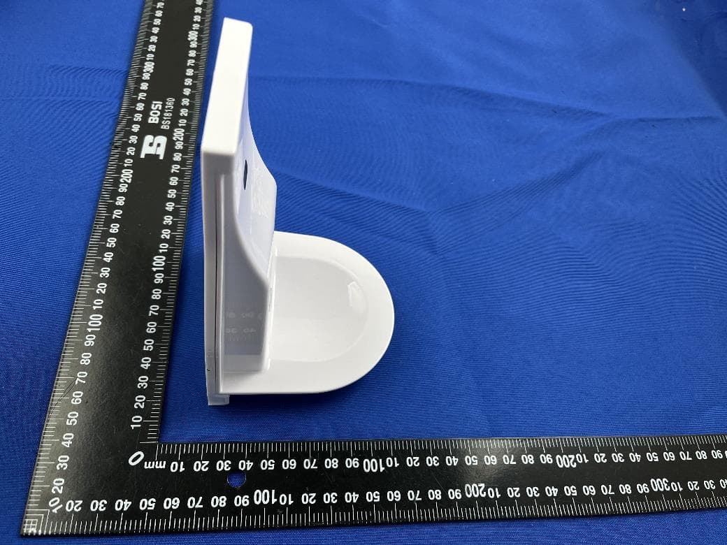
ST2-IT376B
Mar 11, 2022Hand Hygiene Sensor
Equipment Class
DXX - Part 15 Low Power Communication Device Transmitter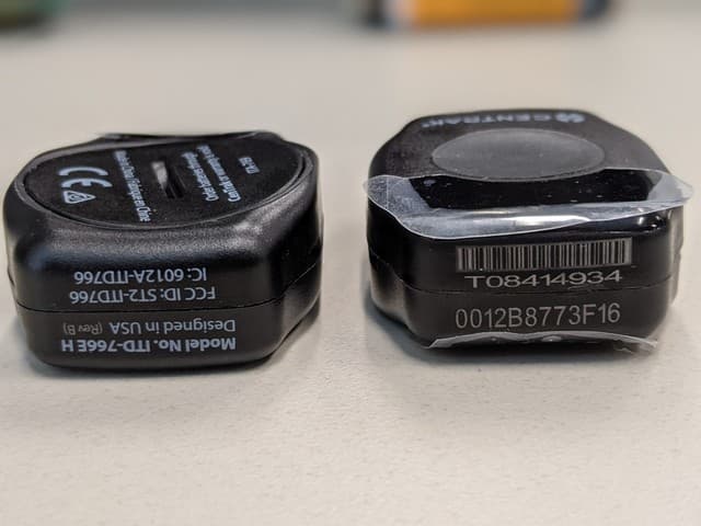
ST2-ITD766
Jun 29, 2021Mini MM Patient/Asset Tag ITD/U-766E/H, -7622E/H,-7623E/H
Equipment Class
DXX - Part 15 Low Power Communication Device Transmitter