ST2-CA100900MHz Frequency Hopping Module
Centrak, Inc.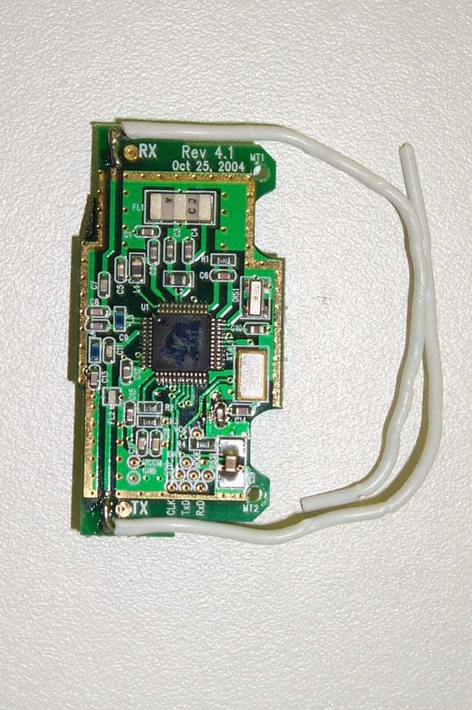
Click to zoom
Application Details
- Equipment Class
- DSS - Part 15 Spread Spectrum Transmitter
- Date of Grant
- Mar 07, 2005
- Application Purpose
- Original Equipment
- Date of Application
- Mar 07, 2005
- Equipment Note
- 900MHz Frequency Hopping Module
- Frequency Range
- 907.00000000 - 923.00000000
- Company
- Centrak, Inc.
- Country
- United States
Documents & Files
Document Text
Text extracted from the exhibit documents filed with the FCC. Open a document above to read the original.
Users Manual
EUT: Frequency Hopping Device Report No: 0048-050207-01 Model: CA100 FCC ID:ST2-CA100 Advanced Compliance Laboratory, Inc. 6 Randolph Way, Hillsborough, NJ 08844, tel:(908) 927 9288 User Manual The CA100 module can be interfaced with the user’s Board through the 20 pin connector designated as GB052A- 20S- H22- TSD- B. This is a standard commercial connector. Remote Play, Inc. software is the only software authorized to operate the module. The software must be integrated by Remote Play, Inc. In order to allow proper operation of the module, the antennas are permanently attached to the module and their shape needs to adhere to the shape below. The antennas must have “guides” to make sure that the antennas comply with the authorized shape as is shown below: The module connector pins are shown in the schematics and should be only used with Remote Play, Inc. Software version RPI-CA100-10. The Vcc voltage must be 3 volts +/- 10% and all the digital signals comply with standard CMOS “1” and “0” requirements. The maximum RSSI signal is 1.6 volts. The maximum data rate that Remote Play, Inc. uses in this module is 16 kbps. The minimum hopping frequency is 907 Mhz. The maximum hopping frequency is 923 Mhz The maximum peak power is less than 7 dBm using any bandwidth. The minimum sensitivity is –103 dBm. Typical communication range is > 500 feet Installation Instructions 1. The module is ESD sensitive and should be handled accordingly. Make sure that a ground strip is used at all time. 2. Before connecting the module make sure that the connection pins adhere to the specs: a. Pins 1,3, 5,6, 16, 17, 18 19 and 20 are properly grounded. CA-100 Module Top View TX Antenna EUT: Frequency Hopping Device Report No: 0048-050207-01 Model: CA100 FCC ID:ST2-CA100 Advanced Compliance Laboratory, Inc. 6 Randolph Way, Hillsborough, NJ 08844, tel:(908) 927 9288 b. Pin 8 should be connected to the power supply. 3 volts controlled (+/- 10%) c. Pin 2 carries an analog RSSI signal and should be routed to avoid close digital lines. d. The rest of the pins are digital pins carrying data and signaling with “1” as 3 volts and 0 as “0”. They should adhere to CMOS type levels. 3. The RF module has its own regulation but the input voltage should be kept within 10% of 3 volts. 4. The device having the module must have a label that states” contains FCC ID: ST2- CA100” besides other required FCC labels for that device. 5. Make sure that the antennas used are not modified and must not be co-located or operated in conjunction with any other antenna or transmitter. FCC Statement The module itself must have a FCC Identifier, “ FCC ID: ST2-CA100”. This device complies with Part 15 of the FCC Rules. Operation is subject to the following two conditions: (1) This device may not cause harmful interference, and (2) this device must accept any interference received, including interference that may cause undesired operation. Caution: The user that changes or modifications not expressly approved by the party responsible for compliance could void the user's authority to operate the equipment. Additional radiated spurious emission evaluation for the additional host device may be required. Statement needed to be shown on End Product Since this module is installed inside the end product, the end product should be affixed a label on visible area showing this product contains a RF model, and also its FCC ID. Important Note This equipment complies with FCC radiation exposure limits set forth for an uncontrolled environment. This transmitter must not be co-located or operating in conjunction with any other antenna or transmitter. The OEM integrator has to be aware not to provide information to the end use regarding how to install or remove this RF module in the user manual of the end product which integrate this module.
Cover Letter(s)
Remote Play Inc. FCC ID: ST2-CA100 Request for transmitter modular approval Transmitter Module Characteristics Item Requirements EUT 1 Have its own RF shielding This device doesn’t have its own shielding. However, we apply for limited portable module approval and typical hosting configuration/requirements will be provided in its manual (OEM installation guideline). As requested, the emissions from the module installed in typical hosting device were investigated. 2 Have buffered modulation/data inputs (if such inputs are provided), The RF Chip buffers all inputs. 3 Have it own power supply regulation Refer to the schematic: The RF chip has an internal power regulator.- pin 25 gives the DC/DC output which indicates that there is a voltage regulation. 4 Meet the antenna requirements of Section 15.203 Our antenna is permanent. 5 Be tested in a stand-alone configuration, i.e., the antenna, AC or DC power and data input/output lines must be connected to the module but, the module must not be inside another case during testing Tested in this way. And module installed in its typical enclosure were tested for limited modular approval. 6 Be labeled with its own FCC ID number, and if the FCC ID is not visible when the module is installed inside another device, then the outside of the device into which the module is installed must also display a label referring to the enclosed module. Two proposed FCC ID label format are included in the filing. One of the labels is to be placed on the module and the other label is to be placed on the outside of system. Refer to FCC ID label format and location file. 7 The modular transmitter is manufactured so that the user cannot influence the operation of the transmitter that will operate outside of the scope of the regulations. Refer to “User’s Manual” Exhibit This is the case – User need to use our software 8 Address compliance with the Commission's RF exposure limits in Sections 1.1310 and 2.1093. In addition, spread spectrum transmitters operating under Section 15.247 are required to address RF exposure compliance in accordance with Section 15.247(b)(4). As stated in #1, extra tests were conducted for portable configuration.
Cover Letter(s)
Helen Zhao Subject: FW: Remote Play Inc., FCC ID: ST2-CA100, Assessment NO.: AN05T4598, Notice#1 3/7/2005 -----Original Message----- From: Weili Sent: Monday, March 07, 2005 8:30 AM To: Helen Zhao Subject: Re: Remote Play Inc., FCC ID: ST2-CA100, Assessment NO.: AN05T4598, Notice#1 Hi, Helen. Attached are Confidential letter, new report with Rx data and Answer for Q1. We are done. thanks agian. Regards, Wei -----Original Message----- From: Weili Sent: Friday, March 05 , 2005 1:29 PM To: Helen Zhao Subject: Re: Remote Play Inc., FCC ID: ST2-CA100, Assessment NO.: AN05T4598, Notice#1 Subject: Remote Play Inc., FCC ID: ST2-CA100, Assessment NO.: AN05T4598, Notice#1 Question #1: No documents in the filing indicate that this is a hybrid device, instead all the documents refer this device as an FHSS device. But the device was tested as a hybrid system, the test report says "there is no requirement of minimum number of hopping channels associated with this type of hybrid system" . Please provide technical information as how the device is qualified as a hybrid system. See below. RPI Hybrid system utilizes 10 frequencies for hopping. As is stated in 15.247 paragraph (f) such a system is not subject to a minimum number of hopping channels as long as it complies with the following: 1.It shares all designated frequency equally. 2.It complies with the maximum power density in 3 KHz bandwidth, i.e. < 8 dbm 3.It uses digital modulation RPI system complies with all the three requirements above: 1. It equally shares each frequency channel. It spends 8.25 milliseconds in each channel. 2. Its maximum transmission power is less than 7 dBm. This was verified over more than 100 sets that were built during the prototype phase. 3.It used FSK modulation that is qualifies as digital modulation The system is not designed to skip frequencies and there is no active methods to avoid collisions. [Helen Zhao] According to FCC Q&A in knowledge database, for hybrid system, "However, the hopping function must be a true hopping system, as described in Section 15.247(a)(1). The specific requirements in Section 15.247(a)(1) are: 1) A minimum channel separation. 2) Pseudo-random hop sequence. 3) Equal use of each frequency. 4) Receiver matching bandwidth and Synchronization. The test report answered #1, but how about #2-4. You may need to provide detailed operational description to address these requirements. For your quick reference, here I provide you FCC guideline. [RPI] (1) The minimum Channel Separation is 1 MHz (2) The Pseudo Random Sequence is generated during manufacturing using a Shift Register Style PN Generator in which the 24 bit seed is the device ID. We then use 8-bit numbers out of the register and select only number from 1 to 10. If a number repeats, we ignore the number. (3) When transmitting we repeat the PN random sequence, so every channel is equally used. We never omit frequencies and never use non-frequency hopping operation in all times. (4) The receiver is a synthesizer based super-heterodyne receiver with a bandwidth of 230 KHz. The 20 dB bandwidth of the system is about 400 KHz and the 3 dB bandwidth is less than 200 KHz. The synchronization is done as followed. The receiver waits in a single frequency. The transmitter continuously hopping in the same sequence defined by the system ID as described above. When the transmitter transmits in the frequency that the receiver is waiting on, the receiver locks onto the transmitter, and because it knows the sequence and timing the receiver starts hopping together with the transmitter. Pseudorandom Frequency Hopping Sequence Describe how the hopping sequence is generated. Provide an example of the hopping sequence channels, in order to demonstrate that the sequence meets the requirement specified in the definition of a frequency hopping spread spectrum system, found in Section 2.1. [RPI] The explanation how the sequence is generated is shown above. An example of ID number [00000011101010101111000] will be the following: Which means that the first frequency to be transmitted is the 4 th in the ordered sequence, the second is the 3 rd , the third is 1 st and so on. Equal Hopping Frequency Use Describe how each individual EUT meets the requirement that each of its hopping channels is used equally on average (e.g., that each new transmission event begins on the next channel in the hopping sequence after the final channel used in the previous transmission event). [RPI] Because we never omit frequencies and each transmission on every channel is the same (about 8 milliseconds), we use every channel equally. Each new transmission event begins on the following channel and after final channel used in the previous transmission event. System Receiver Input Bandwidth Describe how the associated receiver(s) complies with the requirement that its input bandwidth (either RF or IF) matches the bandwidth of the transmitted signal. [RPI] as explained above the IF receiver bandwidth is fixed at 230 KHz (around 10.7 MHz) and matches the bandwidth of the transmitted signal in all channels with 3 dB bandwidth of just about 200 Khz and 20 dB bandwidth of about 400 Khz System Receiver Hopping Capability 4 3 1 5 6 7 9 2 0 8 3/7/2005 Describe how the associated receiver(s) has the ability to shift frequencies in synchronization with the transmitted signals. [RPI] The receiver uses a synthesizer to tune into the right frequency. It shifts frequencies such that it always tuned to the transmitter’s hopping frequency. ************ Question #2: Confidentiality requests must reference Section 0.459 at a minimum because this section provides the authority for such a request. Referencing Section 0.457 is not mandatory but it is suggested because this section lists what information is normally held confidential in equipment authorization filings. Please revise your confidentiality letter accordingly. See attached letter. [Helen Zhao] Please resend. The revised confidential letter is corrupted. Q…
Text truncated - open the document above for the full version.
ID Label/Location Info
EUT: Frequency Hopping Device Report No: 0048-050207-01 Model: CA100 FCC ID:ST2-CA100 Page 69 of 77 Advanced Compliance Laboratory, Inc. 6 Randolph Way, Hillsborough, NJ 08844, tel:(908) 927 9288 FCC Label FCC ID: ST2-CA100 Figure 1 Proposed FCC ID Label on CA100 Module FCC ID: ST2-CA100 Figure 2 Proposed FCC ID Label Location on CA100 Module EUT: Frequency Hopping Device Report No: 0048-050207-01 Model: CA100 FCC ID:ST2-CA100 Page 70 of 77 Advanced Compliance Laboratory, Inc. 6 Randolph Way, Hillsborough, NJ 08844, tel:(908) 927 9288 Contains FCC ID: ST2-CA100 This device complies with part 15 of the FCC Rules. Operating is subject to the following two conditions: (1) This device may not cause harmful interference, and (2) this device must accept any interference received, including interference that may cause undesired operation. Figure 3 Proposed FCC ID Label for CA100 Module Host Device (The statement may be shown in its user manual for small size devices ) FCC ID Label Figure 4 Proposed FCC ID Label location for Host Device (back/bottom)
Internal Photos
EUT: Frequency Hopping Device Report No: 0048-050207-01 Model: CA100 FCC ID:ST2-CA100 Page 75 of 76 Advanced Compliance Laboratory, Inc. 6 Randolph Way, Hillsborough, NJ 08844, tel:(908) 927 9288 PRODUCT PHOTO Component Side EUT: Frequency Hopping Device Report No: 0048-050207-01 Model: CA100 FCC ID:ST2-CA100 Page 76 of 76 Advanced Compliance Laboratory, Inc. 6 Randolph Way, Hillsborough, NJ 08844, tel:(908) 927 9288 Foil Side
Operational Description
EUT: Frequency Hopping Device Report No: 0048-050207-01 Model: CA100 FCC ID:ST2-CA100 Page 75 of 76 Advanced Compliance Laboratory, Inc. 6 Randolph Way, Hillsborough, NJ 08844, tel:(908) 927 9288 OPRATIONAL DESCRIPTION This is a command and control frequency hopping Transceiver module. Once the module is physically connected through the dedicated connector to a “mother board” loaded with Remote Play, Inc. command and control software it allows robust communication, resilient to interference between two such transceivers. Both modules operate as a pair of transmitter/receiver. Once one module initiate its frequency hopping operation the other module will synchronize its predefined frequency hopping sequence with the initiating transceiver. From the moment of synchronization on the two transceivers will hop in unison according to the PN predefined sequence. Power Supply and Ground The transceivers receive their power and ground reference from the mother board. The voltage is 3 volts +/- 10%
Test Setup Photos
EUT: Frequency Hopping Device Report No: 0048-050207-01 Model: CA100 FCC ID:ST2-CA100 Page 63 of 76 Advanced Compliance Laboratory, Inc. 6 Randolph Way, Hillsborough, NJ 08844, tel:(908) 927 9288 RADIATED RF MEASUREMENT SETUP X POSITION EUT: Frequency Hopping Device Report No: 0048-050207-01 Model: CA100 FCC ID:ST2-CA100 Page 64 of 76 Advanced Compliance Laboratory, Inc. 6 Randolph Way, Hillsborough, NJ 08844, tel:(908) 927 9288 Y POSITION EUT: Frequency Hopping Device Report No: 0048-050207-01 Model: CA100 FCC ID:ST2-CA100 Page 65 of 76 Advanced Compliance Laboratory, Inc. 6 Randolph Way, Hillsborough, NJ 08844, tel:(908) 927 9288 Z POSITION EUT: Frequency Hopping Device Report No: 0048-050207-01 Model: CA100 FCC ID:ST2-CA100 Page 66 of 76 Advanced Compliance Laboratory, Inc. 6 Randolph Way, Hillsborough, NJ 08844, tel:(908) 927 9288 Module Hosted in Typical Enclosure, Z POSITION (Worst Case) EUT: Frequency Hopping Device Report No: 0048-050207-01 Model: CA100 FCC ID:ST2-CA100 Page 67 of 76 Advanced Compliance Laboratory, Inc. 6 Randolph Way, Hillsborough, NJ 08844, tel:(908) 927 9288 Typical Hosting Device for Module
Contact Information
Applicant
Sherre Staves(VP)
Test Firm
Advanced Compliance LaboratoryWei Li
Technical Specifications
| # | Rule Parts | Frequency Range | Power Output |
|---|---|---|---|
| 1 | 15C | 907 MHz - 923 MHz | 3.90 mW |
Other Applications from Centrak, Inc.
ST2-IT7210
Feb 13, 2026Safety 2.0 Bracelet
Equipment Class
DXX - Part 15 Low Power Communication Device Transmitter
ST2-CTHSB760
Mar 17, 2024BLE MultiMode Badge
Equipment Class
DTS - Digital Transmission System
ST2-5MDT000371
Apr 06, 2022Man Down
Equipment Class
DTS - Digital Transmission System
ST2-IT376B
Mar 11, 2022Hand Hygiene Sensor
Equipment Class
DXX - Part 15 Low Power Communication Device Transmitter
ST2-ITD766
Jun 29, 2021Mini MM Patient/Asset Tag ITD/U-766E/H, -7622E/H,-7623E/H
Equipment Class
DXX - Part 15 Low Power Communication Device Transmitter