ST2-DM32YMULTI-MODE VIRTUAL WALL ITD-325 &IT-323A
Centrak, Inc.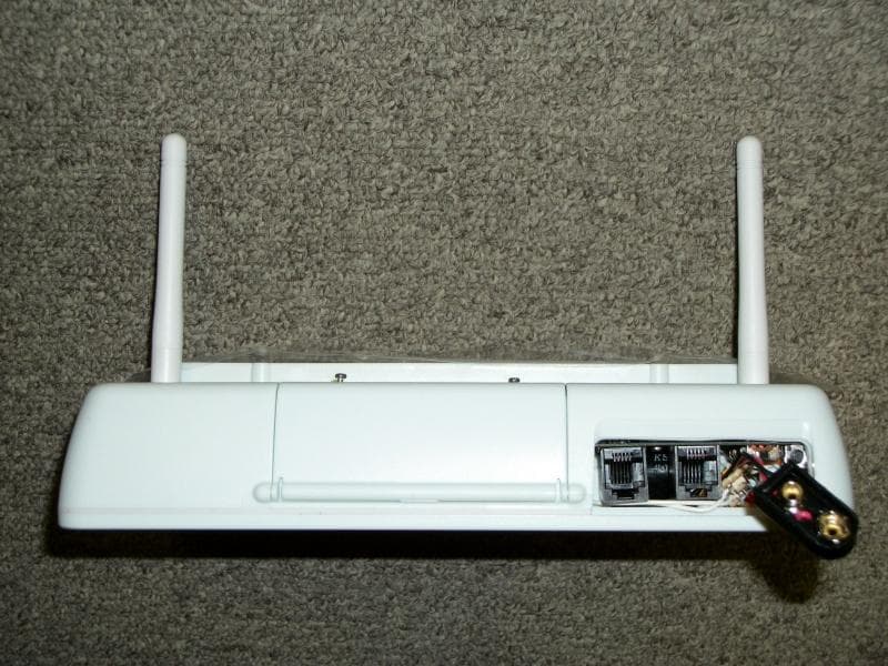
Click to zoom
Application Details
- Equipment Class
- DXT - Part 15 Low Power Transceiver, Rx Verified
- Date of Grant
- Feb 20, 2013
- Application Purpose
- Original Equipment
- Date of Application
- Feb 20, 2013
- Equipment Note
- MULTI-MODE VIRTUAL WALL ITD-325 &IT-323A
- Frequency Range
- 904.00000000 - 926.00000000
- Company
- Centrak, Inc.
- Country
- United States
Documents & Files
Document Text
Text extracted from the exhibit documents filed with the FCC. Open a document above to read the original.
Users Manual
© CenTrak 2013. All Rights Reserved. Proprietary and Confidential. CenTrak, Inc. 5 Caufield Place, Suite 102 Newtown, PA 18940 t: 215‐860‐2928 e: [email protected] www.centrak.com ITDK‐325 Multi‐Mode Virtual Wall •CCX on Wi‐Fi networks and Gen2IR™ •No physical wall or curtain needed to limit area being divided •Semi‐private room separation to accurately locate an asset or person on either side of the room •Division of bays or bed areas typically important in ER and OR Pre‐Op/Post‐Op settings •Battery operated for simple installation •Can be configured and monitored by central server for superior control •Simple to install clip‐on ceiling mounting bracket The Multi‐Mode Virtual Wall is a Gen2IR (infrared) signaling unit used with IR‐ enabled tags to provide a method of locating tagged assets or people for facilities that require sub‐room level accuracy. Virtual Walls are geared to semi‐private rooms and bays typically found in ER and OR settings. Unlike room‐level monitors, Virtual Walls do not need physical walls to limit the area of coverage. It functions in both 900 MHz and/or Wi‐Fi environments without any wiring. About CenTrak Gen2IR™ Technology™ The CenTrak proprietary IR protocol achieves a marked improvement over conventional IR protocols that were designed for remote control applications. It provides superior resilience to fluorescent and other common indoor interference sources. Coverage zones are limited by solid physical structures such as walls; however, contrary to popular belief, IR does not need line of sight for effective communication. IR signals bounce effectively from structures and walls flood the entire room including locations that are not in direct line of sight to the monitor. The battery operation and the extremely simple mounting mechanism allows for the quick and low cost installation. ITDK‐325 CenTrak Virtual Wall Monitor ITDK‐325 CenTrak Virtual Wall shown mounted to a ceiling © CenTrak 2013. All Rights Reserved. Proprietary and Confidential. CenTrak, Inc. 5 Caufield Place, Suite 102 Newtown, PA 18940 t: 215‐860‐2928 e: [email protected] www.centrak.com ITDK‐325 Multi‐Mode Virtual Wall Technical Specifications Operation FCC Operating Frequency Range2.4 GHz (CCX on Wi‐Fi networks, 802.11 b/g) 902‐928 MHz Bay Area Coverage Maximum Room Size14’ long x 12’ wide (12’ high) Minimum Room Size8’ long x 6’ wide (7’ high) Wall ThicknessUp to 1’ Product Dimensions Base Width5.5 in (139.7 mm) Base Length8.5 in (215.9 mm) Base Depth1.5 in (38.1 mm) Base Weight18.5 oz (0.53 kg) MountingCeiling tile clip, above ceiling tile Environmental Operating Temperature0 C to +50 C Storage temperature‐20 C to +70 C Operating Humidity10% to 90% non‐condensing Power Battery typePre‐installed 2xD Lithium (Extra battery pack available). ITDK‐325 CenTrak Virtual Wall Monitor ITDK‐325 CenTrak Virtual Wall shown mounted to ceiling THIS DEVICE COMPLIES WITH PART 15 OF THE FCC RULES AND INDUSTRY CANADA LICENSE‐EXEMPT RSS STANDARD(S). OPERATION IS SUBJECT TO THE FOLLOWING TWO CONDITIONS: (1) THIS DEVICE MAY NOT CAUSE HARMFUL INTERFERENCE, AND (2) THIS DEVICE MUST ACCEPT ANY INTERFERENCE RECEIVED, INCLUDING INTERFERENCE THAT MAY CAUSE UNDESIRED OPERATION. Modifying or tampering with the transceiver’s or receiver’s internal components can cause a malfunction, invalidate the warranty, and will void FCC authorization to use these products. This product or its systems are covered by one or more of the following U.S. patents: 5,917,425, 7,061,428, 7,378,964, 7,619,532 L ‘ utilisation de ce dispositif est autorisée seulement aux conditions suivantes : (1) il ne doit pas produire de brouillage et (2) l’ utilisateur du dispositif doit étre prêt à accepter tout brouillage radioélectrique reçu, même si ce brouillage est susceptible de compromettre le fonctionnement du dispositif. © CenTrak 2013. All Rights Reserved. Proprietary and Confidential. CenTrak, Inc. 5 Caufield Place, Suite 102 Newtown, PA 18940 t: 215‐860‐2928 e: [email protected] www.centrak.com ITDK‐325 Multi‐Mode Virtual Wall Accessories ITA‐371 VW Monitor Ceiling Attachment (9/16 inch) ITA‐372 VW Monitor Ceiling Attachment (15/16 inch) Standard ITDK‐325 CenTrak Virtual Wall Monitor ITA‐365 VW Monitor & Battery Pack Connector Cable (1 pack) ITA‐367 VW Monitor & Battery Pack Connector Cable (2 pack) Ceiling Attachments Power IR Blocker ITA‐366 VW Monitor IR Blocker –4 inch ITA‐359 IR Regenerator VW Monitor ITA‐357 2D Cell Lithium Batteries in Pack for VW Monitor (2 pack) ITDK‐325 CenTrak Virtual Wall shown mounted to ceiling ITA‐373 VW Monitor Ceiling Attachment (15/16 inch) Long ITA‐356 D Cell Lithium Battery (2) (for illustration purposes only)
Users Manual
© CenTrak 2013. All Rights Reserved. Proprietary and Confidential. 1/03 CenTrak, Inc. 5 Caufield Place, Suite 102 Newtown, PA 18940 t: 215‐860‐2928 e: [email protected] www.centrak.com CenTrak Virtual Wall IT‐323* •No physical wall or curtain needed to limit area being divided •Semi‐private room separation to accurately locate an asset or person on either side of the room •Division of bays or bed areas typically important in ER and OR Pre‐Op/Post‐Op settings •Battery operated for simple installation, up to 7 years battery life (based on configuration) •Can be configured and monitored by central server for superior control •Simple to install clip‐on ceiling mounting bracket The Virtual Wall is a Gen2IR (infrared) signaling unit used with IR‐enabled tags to provide a method of locating tagged assets or people for facilities that require sub‐room level accuracy. Virtual Walls are geared to semi‐private rooms and bays typically found in ER and OR settings. Unlike room‐level monitors, Virtual Walls do not need physical walls to limit the area of coverage. About CenTrak Hybrid RTLS Technology™ The CenTrak core RTLS differs from legacy in its combined use of a patented second‐generation infrared (Gen2IR™) and active RFID technology. Battery powered monitors transmit a unique room number using Gen2IR ,which is received by any tag in that room. The tag communicates the room number and its own unique ID via RF to the CenTrak Location Server using a hospital’s existing wired or WiFi network, where it can be accessed in real‐time by hospital personnel and integrated with third party solution providers. *IT‐323 is for use with the CenTrak 2.0 system. Order IT‐321 for use with the 1.0 system. IT‐323 CenTrak Virtual Wall Monitor IT‐323 CenTrak Virtual Wall shown mounted to a ceiling © CenTrak 2013. All Rights Reserved. Proprietary and Confidential. 1/03 CenTrak, Inc. 5 Caufield Place, Suite 102 Newtown, PA 18940 t: 215‐860‐2928 e: [email protected] www.centrak.com CenTrak Virtual Wall IT‐323* Technical Specifications Operation FCC Operating Frequency Range902‐928 MHz (Model #IT‐323)* CE Operating Frequency Range868‐870 MHz (Model #ITEU‐323)* Power ControlLocal on/off, Remote on/off Default SettingFactory set location code –marked on Monitor IndicatorsNone Bay Area Coverage Maximum Room Size14’ long x 12’ wide (12’ high)** Minimum Room Size8’ long x 6’ wide (7’ high)** Wall ThicknessUp to 1’ Product Dimensions Base Width5.5 in (139.7 mm) Base Length8.5 in (215.9 mm) Base Depth1.5 in (38.1 mm) Base Weight18.5 oz (0.53 kg) MountingCeiling tile clip, above ceiling tile Environmental Operating Temperature0 C to +50 C Storage temperature‐20 C to +70 C Operating Humidity10% to 90% non‐condensing Power Battery typePre‐installed 2xD Lithium (Extra battery pack available). Up to 3‐7 years battery life based on configuration *IT‐323 is for use with the CenTrak 2.0 system. Order IT‐321 for use with the 1.0 system. THIS DEVICE COMPLIES WITH PART 15 OF THE FCC RULES AND INDUSTRY CANADA LICENSE‐EXEMPT RSS STANDARD(S). OPERATION IS SUBJECT TO THE FOLLOWING TWO CONDITIONS: (1) THIS DEVICE MAY NOT CAUSE HARMFUL INTERFERENCE, AND (2) THIS DEVICE MUST ACCEPT ANY INTERFERENCE RECEIVED, INCLUDING INTERFERENCE THAT MAY CAUSE UNDESIRED OPERATION. Modifying or tampering with the transceiver’s or receiver’s internal components can cause a malfunction, invalidate the warranty, and will void FCC authorization to use these products. This product or its systems are covered by one or more of the following U.S. patents: 5,917,425, 7,061,428, 7,378,964, 7,619,532 L ‘ utilisation de ce dispositif est autorisée seulement aux conditions suivantes : (1) il ne doit pas produire de brouillage et (2) l’ utilisateur du dispositif doit étre prêt à accepter tout brouillage radioélectrique reçu, même si ce brouillage est susceptible de compromettre le fonctionnement du dispositif. IT‐323 CenTrak Virtual Wall Monitor IT‐323 CenTrak Virtual Wall shown mounted to ceiling © CenTrak 2013. All Rights Reserved. Proprietary and Confidential. 1/03 CenTrak, Inc. 5 Caufield Place, Suite 102 Newtown, PA 18940 t: 215‐860‐2928 e: [email protected] www.centrak.com CenTrak Virtual Wall IT‐323* Accessories *IT‐323 is for use with the CenTrak 2.0 system. Order IT‐321 for use with the 1.0 system. ITA‐371 VW Monitor Ceiling Attachment (9/16 inch) ITA‐372 VW Monitor Ceiling Attachment (15/16 inch) Standard IT‐323 CenTrak Virtual Wall Monitor ITA‐365 VW Monitor & Battery Pack Connector Cable (1 pack) ITA‐367 VW Monitor & Battery Pack Connector Cable (2 pack) Ceiling Attachments Power IR Blocker ITA‐366 VW Monitor IR Blocker –4 inch ITA‐359 IR Regenerator VW Monitor ITA‐357 2D Cell Lithium Batteries in Pack for VW Monitor (2 pack) IT‐323 CenTrak Virtual Wall shown mounted to ceiling ITA‐373 VW Monitor Ceiling Attachment (15/16 inch) Long ITA‐356 D Cell Lithium Battery (2) (for illustration purposes only)
Cover Letter(s)
Date: January 27, 2013 FCC and IC Confidentiality Request In accordance with 0.459 & 0.457 of CFR 47, please, accept this letter as an official request to have the following kept as confidential for the reference IDs: IC: 6012A-ITD325 with the following model numbers: ITD-325, and IT-323A And: FCC: ST2-DM32Y The information provided is for the sole purpose of inclusion as exhibits in the Application for Certificate of the FCC & IC IDs stated above: We ask to keep confidential the following Tag (model# ITD-325, IT-323A) documents: Schematics Block Diagram Operational description Sincerely, Israel Amir, CTO CenTrak, Inc. 5 Caufield Place, Ste 102 Newtown, PA 18940 215.860.2928
External Photos
FCC ID: ST2-DM32Y ——————————————————————————————————————————————— Advanced Compliance Lab, 6 Randolph Way, Hillsborough, NJ 08844 Tel: (908) 927-9288 Fax: (908) 927-0728 19 7.1 Top View FCC ID: ST2-DM32Y ——————————————————————————————————————————————— Advanced Compliance Lab, 6 Randolph Way, Hillsborough, NJ 08844 Tel: (908) 927-9288 Fax: (908) 927-0728 20 7.2 Back View FCC ID: ST2-DM32Y ——————————————————————————————————————————————— Advanced Compliance Lab, 6 Randolph Way, Hillsborough, NJ 08844 Tel: (908) 927-9288 Fax: (908) 927-0728 24 7.6 EUT Front Side View 7.7 EUT Real Side View FCC ID: ST2-DM32Y ——————————————————————————————————————————————— Advanced Compliance Lab, 6 Randolph Way, Hillsborough, NJ 08844 Tel: (908) 927-9288 Fax: (908) 927-0728 25 7.8 EUT Right Side View 7.9 EUT Left Side View
ID Label/Location Info
FCC ID: ST2-DM32Y ——————————————————————————————————————————————— Advanced Compliance Lab, 6 Randolph Way, Hillsborough, NJ 08844 Tel: (908) 927-9288 Fax: (908) 927-0728 8 2. PRODUCT LABELING Figure 2.1 FCC ID Label Figure 2.2 Location of Label on the Side of EUT Figure 2.2 FCC Label Location FCC ID: ST2-DM32Y *Contains FCC ID: ST2-CEN8B This device complies with part 15 of the FCC Rules. Operating is subject to the following two conditions: (1) This device may not cause harmful interference, and (2) this device must accept any interference received, including interference that may cause undesired operation. Figure 2.1 FCC ID Label (* This line is for Model ITD-325 Only) FCC Label
ID Label/Location Info
FCC ID: ST2-DM32Y ——————————————————————————————————————————————— Advanced Compliance Lab, 6 Randolph Way, Hillsborough, NJ 08844 Tel: (908) 927-9288 Fax: (908) 927-0728 8 2. PRODUCT LABELING Figure 2.1 FCC ID Label Figure 2.2 Location of Label on the Side of EUT Figure 2.2 FCC Label Location FCC ID: ST2-DM32Y *Contains FCC ID: ST2-CEN8B This device complies with part 15 of the FCC Rules. Operating is subject to the following two conditions: (1) This device may not cause harmful interference, and (2) this device must accept any interference received, including interference that may cause undesired operation. Figure 2.1 FCC ID Label (* This line is for Model ITD-325 Only) FCC Label
Internal Photos
FCC ID: ST2-DM32Y ——————————————————————————————————————————————— Advanced Compliance Lab, 6 Randolph Way, Hillsborough, NJ 08844 Tel: (908) 927-9288 Fax: (908) 927-0728 21 7.3 Inside View FCC ID: ST2-DM32Y ——————————————————————————————————————————————— Advanced Compliance Lab, 6 Randolph Way, Hillsborough, NJ 08844 Tel: (908) 927-9288 Fax: (908) 927-0728 22 7.4 PCB Component Side View FCC ID: ST2-DM32Y ——————————————————————————————————————————————— Advanced Compliance Lab, 6 Randolph Way, Hillsborough, NJ 08844 Tel: (908) 927-9288 Fax: (908) 927-0728 23 7.5 PCB Foil Side View FCC ID: ST2-DM32Y ——————————————————————————————————————————————— Advanced Compliance Lab, 6 Randolph Way, Hillsborough, NJ 08844 Tel: (908) 927-9288 Fax: (908) 927-0728 26 7.10 External Antenna View FCC ID: ST2-DM32Y ——————————————————————————————————————————————— Advanced Compliance Lab, 6 Randolph Way, Hillsborough, NJ 08844 Tel: (908) 927-9288 Fax: (908) 927-0728 27 7.11 Close up of the 904-926 MHz transmitter
Test Report
ELECTROMAGNETIC EMISSION COMPLIANCE REPORT of Multi-Mode Virtual Wall MODEL: ITD-325 & IT-323A FCC ID: ST2-DM32Y January 16, 2013 This report concerns (check one): Original grant x Class II change Equipment type: Low Power Intentional Radiator Deferred grant requested per 47 CF 0.457(d)(1)(ii)? yes no x If yes, defer until: (date) Company agrees to notify the Commission by (date) of the intended date of announcement of the product so that the grant can be issued on that date. Transition Rules Request per 15.37? yes no x If no, assumed Part 15, Subpart B for unintentional radiators - the new 47 CFR [10-1-90 Edition] provision. Report prepared for: CENTRAK, INC. Report prepared by: Advanced Compliance Lab Report number: 0048-130114-01-FCC Lab Code: 200101 The test result in this report IS supported and covered by the NVLAP accreditation 6 Randolph Way Hillsborough, NJ 08844 Tel: (908) 927 9288 Fax: (908) 927 0728 Advanced Compliance Laboratory FCC ID: ST2-DM32Y ——————————————————————————————————————————————— Advanced Compliance Lab, 6 Randolph Way, Hillsborough, NJ 08844 Tel: (908) 927-9288 Fax: (908) 927-0728 2 Table of Contents Report Cover Page .................................................................................................... 1 Table of Contents ...................................................................................................... 2 Figures ....................................................................................................................... 3 1. GENERAL INFORMATION .................................................................................. 4 1.1 Verification of Compliance ......................................................................... 4 1.2 Equipment Modifications ............................................................................ 5 1.3 Product Information ................................................................................... 6 1.4 Test Methodology ...................................................................................... 6 1.5 Test Facility ............................................................................................... 6 1.6 Test Equipment .......................................................................................... 6 1.7 Statement for the Document Use ................................................................ 7 2. PRODUCT LABELING .......................................................................................... 8 3. SYSTEM TEST CONFIGURATION ...................................................................... 9 3.1 Justification ................................................................................................ 9 3.2 Special Accessories .................................................................................... 9 3.3 Configuration of Tested System.................................................................. 9 4. SYSTEM SCHEMATICS ....................................................................................... 12 5. RADIATED EMISSION DATA ............................................................................. 13 5.1 Field Strength Calculation .......................................................................... 13 5.2 Test Methods and Conditions ..................................................................... 13 5.3 Test Data ................................................................................................... 13 6. EUT RECEIVING MODE VERIFICATION .......................................................... 17 7. PHOTOS OF TESTED EUT ................................................................................... 18 FCC ID: ST2-DM32Y ——————————————————————————————————————————————— Advanced Compliance Lab, 6 Randolph Way, Hillsborough, NJ 08844 Tel: (908) 927-9288 Fax: (908) 927-0728 3 Figures Figure 2.1 FCC ID Label ........................................................................................... 8 Figure 2.2 Location of Label on Back of the EUT.................................................... 8 Figure 3.1 Radiated Test Setup, Position 1 .............................................................. 10 Figure 4.1 EUT Schematics ....................................................................................... 12 Figure 7.1 Top View .................................................................................................. 19 Figure 7.2 Back View ................................................................................................ 20 Figure 7.3 Inside View ............................................................................................... 21 Figure 7.4 PCB Component Side View ..................................................................... 22 Figure 7.5 PCB Foil Side View .................................................................................. 23 Figure 7.6 EUT Front Side View............................................................................... 24 Figure 7.7 EUT Rear Side View ................................................................................ 24 Figure 7.8 EUT Right Side View ............................................................................... 25 Figure 7.9 EUT Left Side View ................................................................................. 25 Figure 7.10 External Antenna View .......................................................................... 26 Figure 7.11 Close Up of the 904-926MHZ Transmitter .......................................... 27 FCC ID: ST2-DM32Y ——————————————————————————————————————————————— Advanced Compliance Lab, 6 Randolph Way, Hillsborough, NJ 08844 Tel: (908) 927-9288 Fax: (908) 927-0728 4 1. GENERAL INFORMATION 1.1 Verification of Compliance EUT: Multi-Mode Virtual Wall Model: ITD-325 & IT-323A Applicant: CENTRAK, INC. Test Type: FCC Part 15C CERTIFICATION* Result: PASS Tested by: ADVANCED COMPLIANCE LABORATORY Test Date: January 16, 20…
Text truncated - open the document above for the full version.
Test Setup Photos
FCC ID: ST2-DM32Y ——————————————————————————————————————————————— Advanced Compliance Lab, 6 Randolph Way, Hillsborough, NJ 08844 Tel: (908) 927-9288 Fax: (908) 927-0728 10 Figure 3.1 Radiated Test Setup FCC ID: ST2-DM32Y ——————————————————————————————————————————————— Advanced Compliance Lab, 6 Randolph Way, Hillsborough, NJ 08844 Tel: (908) 927-9288 Fax: (908) 927-0728 11 FCC ID: ST2-DM32Y ——————————————————————————————————————————————— Advanced Compliance Lab, 6 Randolph Way, Hillsborough, NJ 08844 Tel: (908) 927-9288 Fax: (908) 927-0728 12 4. SYSTEM SCHEMATICS See Attachment Figure 4.1 System Schematics
Contact Information
Applicant
Sherre Staves(VP)
Test Firm
Advanced Compliance LaboratoryWei Li
Technical Specifications
| # | Rule Parts | Frequency Range | Power Output |
|---|---|---|---|
| 1 | 15C | 904 MHz - 926 MHz | - |
Other Applications from Centrak, Inc.
ST2-IT7210
Feb 13, 2026Safety 2.0 Bracelet
Equipment Class
DXX - Part 15 Low Power Communication Device Transmitter
ST2-CTHSB760
Mar 17, 2024BLE MultiMode Badge
Equipment Class
DTS - Digital Transmission System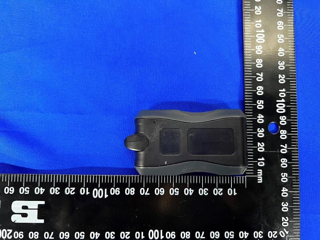
ST2-5MDT000371
Apr 06, 2022Man Down
Equipment Class
DTS - Digital Transmission System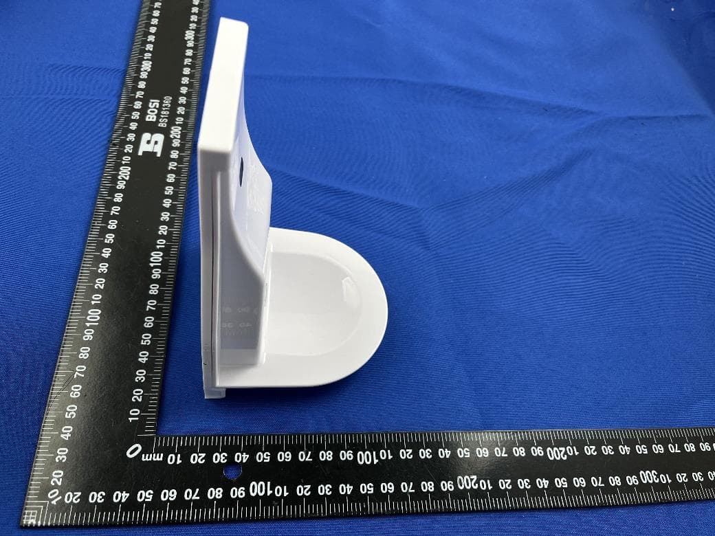
ST2-IT376B
Mar 11, 2022Hand Hygiene Sensor
Equipment Class
DXX - Part 15 Low Power Communication Device Transmitter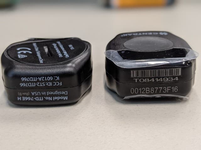
ST2-ITD766
Jun 29, 2021Mini MM Patient/Asset Tag ITD/U-766E/H, -7622E/H,-7623E/H
Equipment Class
DXX - Part 15 Low Power Communication Device Transmitter