ST8TRILOC01TRiLOC GPS Locator
SafeTracks GPS Canada Inc.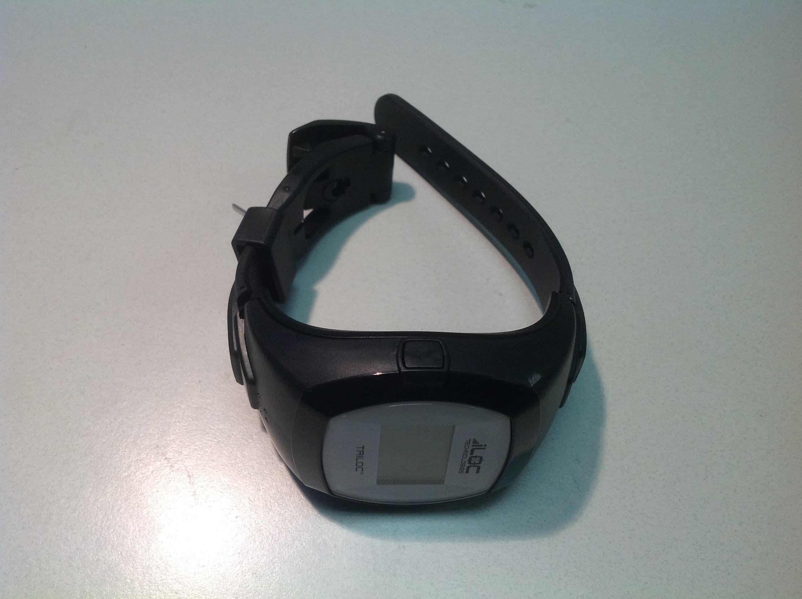
Click to zoom
Application Details
- Equipment Class
- PCB - PCS Licensed Transmitter
- Date of Grant
- Apr 28, 2013
- Application Purpose
- Original Equipment
- Date of Application
- Apr 28, 2013
- Equipment Note
- TRiLOC GPS Locator
- Frequency Range
- 1852.40000000 - 1907.60000000
- Company
- SafeTracks GPS Canada Inc.
- Country
- Canada
Documents & Files
Document Text
Text extracted from the exhibit documents filed with the FCC. Open a document above to read the original.
Users Manual
1 Safety and Regulatory Guide Rev. 1.04 Peace of Mind Solutions! SAFETY and REGULATORY GUIDE 2 Safety and Regulatory Guide Rev. 1.04 Safety and Regulatory Guide PLEASE READ BEFORE PROCEEDING THE TRILOC™ GPS LOCATOR BATTERY IS NOT FULLY CHARGED WHEN YOU TAKE IT OUT OF THE BOX. PLEASE REFER TO THE QUICK START GUIDE INCLUDED IN THE BOX FOR CHARGING INSTRUCTIONS. YOUR WARRANTY SHALL BE DEEMED INVALID SHOULD YOU DISASSEMBLE OR ATTEMPT TO DISASSEMBLE THE TRILOC™ GPS LOCATOR. Disclaimers ANY WEATHER, STOCK, OR OTHER INFORMATION, DATA, OR DOCUMENTATION (“Accessed Information”) ARE PROVIDED “AS IS” AND WITHOUT ANY WARRANTY (EXPRESS OR IMPLIED) OR ANY TECHNICAL SUPPORT. TO THE MAXIMUM EXTENT PERMITTED BY APPLICABLE LAW, iLOC Technologies Inc. AND ITS AFFILIATES EXPRESSLY DISCLAIM ANY AND ALL REPRESENTATIONS AND WARRANTIES, ARISING BY LAW OR OTHERWISE, RELATED TO THE ACCESSED INFORMATION, INCLUDING WITHOUT LIMITATION ANY EXPRESSED OR IMPLIED REPRESENTATION OR WARRANTY OF MERCHANTABILITY, FITNESS FOR A PARTICULAR PURPOSE, NON- INFRINGEMENT, QUALITY, ACCURACY, COMPLETENESS, EFFECTIVENESS, RELIABILITY, OR USEFULNESS. WITHOUT LIMITING THE FOREGOING, IT IS FURTHER UNDERSTOOD THAT ILOC TECHNOLOGIES AND ITS AFFILIATES ARE NOT RESPONSIBLE FOR ANY USE OF THE ACCESSED INFORMATION OR THE RESULTS ARISING FROM SUCH USE, AND THAT YOU USE SUCH INFORMATION AT YOUR OWN RISK. ILOC TECHNOLOGIES DOES NOT WARRANT THAT THE PRODUCT WILL: (A) WORK PERFECTLY; (B) NOT NEED OCCASIONAL UPGRADES OR MODIFICATIONS; OR (C) NOT BE NEGATIVELY AFFECTED BY NETWORK RELATED MODIFICATIONS, UPGRADES OR SIMILAR ACTIVITY. FURTHERMORE, THERE IS NO WARRANTY THAT SERVICE WILL BE: (A) UNINTERRUPTED OR ERROR FREE; OR (B) FREE FROM LOSS, CORRUPTION, ATTACK, VIRUSES, INTERFERENCE, AND HACKING OR OTHER SECURITY INTRUSION. THE TRILOC GPS LOCATOR (WITH OR WITHOUT SERVICE OFFERED) IS NOT A MEDICAL DEVICE, IS NOT A LIFE SAVING DEVICE AND IS TO BE CONSIDERED AS A BACK-UP DEVICE TO ANY AND ALL RECOMMENDED PRACTICES. Privacy restrictions The software used will provide iLOC Technologies Inc. with limited access to your computer system, Smart Phone and/or wireless device. Among other things, the software will provide iLOC Technologies with information related to historical locations and the performance of the device. Information concerning the location of the TRiLOC GPS Locator may also be used by iLOC Technologies and its licensors in support for trouble analysis procedures. Limitation of Damages BY USING THE TRILOC GPS LOCATOR, THE USER AGREES, TO THE EXTENT PERMITTED BY LAW, TO INDEMNIFY AND HOLD ILOC TECHNOLOGIES INC., ITS DIRECTORS, OFFICERS, EMPLOYEES, AFFILIATES, AGENTS, CONTRACTORS, AND LICENSORS HARMLESS WITH RESPECT TO ANY CLAIMS ARISING OUT OF FAILURE OR DELAY TO USE ANY SERVICE AND/OR THE TRILOC GPS LOCATOR, OR ANY 3 Safety and Regulatory Guide Rev. 1.04 ACTION TAKEN BY ILOC TECHNOLOGIES AS PART OF ITS INVESTIGATION OF A SUSPECTED VIOLATION OF THIS AGREEMENT OR OTHER INVESTIGATION REASONABLY REQUIRED. ILOC TECHNOLOGIES IS NOT RESPONSIBLE FOR INFORMATION DELETED FROM OR INACCURATELY PORTRAYED ON THE USER’S ACCOUNT OR DEVICE. Health Information & Safety Precautions When using the TRiLOC GPS Locator or any of its accessories, the safety precautions described herein must be taken to avoid possible legal liabilities and damages. The user should retain and follow all product safety and operating instructions. Observe all warnings in the operating instructions of the product and the services associated with the product. To reduce the risk of bodily injury, electric shock, fire and damage to the TRiLOC GPS Locator or its accessories, observe the following precautions. Electrical Safety This product is intended for use when supplied with power from the integrated battery or approved charging unit. Other usage may be dangerous and will invalidate any approval given to this product. Safety precautions for proper grounding installation CAUTION: Connecting to improperly grounded equipment can result in an electric shock to the product. The TRiLOC GPS Locator is equipped with a USB Cable that can be connected to desktop or laptop computers. Be sure your computer is properly grounded to earth ground before connecting this product to your computer. The computer power supply cord includes an equipment grounding conductor and grounding plug. The computer plug must be plugged into a suitable power outlet which is properly installed and grounded according to all local building and electrical codes and ordinances. Safety precautions for charging CAUTION: Use the correct external power source when using charging devices powered from AC line voltage. A charging device should only be operated from the type of power source indicated on its electrical ratings label. If you are not sure of the type of power source required, consult an authorized service provider or local power company. Refer to the Owner’s Manual or Quick Start Guide for information regarding charging of the TRiLOC GPS Locator. BATTERY: Your TRiLOC GPS Locator incorporates a Lithium-Ion Polymer battery that can only be serviced by iLOC Technologies or its authorized Affiliates. There is a risk of fire or burns if the battery is handled improperly. Do not attempt to open or service the battery. Do not disassemble, crush, puncture the case, puncture the microphone or speaker water proof membranes, dispose of in fire or water, or expose the TRiLOC GPS Locator to temperatures higher then 60C (140F). WARNING: Danger of explosion if the battery is incorrectly serviced. To reduce the risk of fire or burns, do not disassemble, crush, puncture, dispose of in fire or water, or expose the TRiLOC GPS Locator to temperatures higher then 60C (140F). 4 Safety and Regulatory Guide Rev. 1.04 WARNING: IF YOUR TRILOC GPS LOCATOR IS DAMAGED, PERFORATED OR SHOWS SIGNS OF WATER INFILTRATION, REMOVE FROM THE PERSON AND STOP USING THE LOCATOR IMMEDIATELY AND DO NOT EXPOSE THE LOCATOR TO WATER AS THE BATTERY MAY CATCH FIRE OR EX…
Text truncated - open the document above for the full version.
Attestation Statements
C,nterion Wireless Modules GmbH· Siemensdamm 50 • 13629 Bertin • Genmany iLOC Teehnologies Ine. Name Thorsten Liebig 1870 Sources Blvd, Suite #205 Department Approvals Poine-CI1aire, Quebee H9R 5N4 Phone +493031102-8241 Canada Fax +493031102-8305 E-Mail [email protected] Your letter 01 Our relerence Date 12 March 2013 Approval for iLOC Teehnologies Ine to re use test reports from Cinterion PHS8-P issued by 7Layers AG for iLOC Teehnologies Ine produets Dear Sir or Madam, We, Cinterion Wireless Modules GmbH; St. Martin Str. 60; 81541 München hereby authorise iLOC Teehnologies Ine to re use our Test Reports in support of their applieation TRiLOC, for whieh TUV SUD Ameriea Ine is the appointed test house. Sineerely yours, _/ t!u~. ß)~/ld'2 Thorsten Liebig Dr. Jörg Rook Manager Approval Head of System Test Authorized Signature for Cinterion Wireless Modules GmbH Registered office: Managing directors: Commercial register, Reg. no.: Cinterion Wireless Modules GmbH Norbert Muhrer, Sebastien Gallois Amtsgericht München, HRB 172715 St.-Martin-Straße 60 WEEE-Reg.-Nr. DE 58893809 81541 München Germany
External Photos
IC ID: 10925A-TRILOC01 FCCID:ST8TRILOC01
ID Label/Location Info
TRiLOC GPS LocatorModel: iL1000 Designed in Canada. Made in China. FCC ID: ST8TRILOC01 IC ID: 10925A-TRILOC01 PATENTS PENDING 2.25 cm TM TM iLOC Technologies Inc. 2.5 cm
RF Exposure Info
802 N. Twin Oaks Valley Road, Suite 105 • San Marcos, CA 92069 • U.S.A. TEL (760) 471-2100 • FAX (760) 471-2121 http://www.rfexposurelab.com CERTIFICATE OF COMPLIANCE SAR EVALUATION iLoc Technologies, Inc. Dates of Test: March 20-21, 2013 1870 Boul. Des Sources, Suite 205 Test Report Number: SAR.20130304 Pointe-Claire, Quebec H9R 5N4 Canada Revision B This wireless mobile and/or portable device has been shown to be compliant for localized specific absorption rate (SAR) for uncontrolled environment/general exposure limits specified in ANSI/IEEE Std. C95.1-1992 and had been tested in accordance with the measurement procedures specified in IEEE 1528-2003, and OET Bulletin 65 Supp. C (See test report). I attest to the accuracy of the data. All measurements were performed by myself or were made under my supervision and are correct to the best of my knowledge and belief. I assume full responsibility for the completeness of these measurements and vouch for the qualifications of all persons taking them. RF Exposure Lab, LLC certifies that no party to this application is subject to a denial of Federal benefits that includes FCC benefits pursuant to Section 5301 of the Anti-Drug Abuse Act of 1988, 21 U.S.C. 853(a). Jay M. Moulton Vice President Certificate # 2387.01 FCC ID: ST8TRILOC01 IC Certificate: 10925A-TRILOC01 Model(s): TriLoc Test Sample: Engineering Unit Same as Production S/N Number: 75 Equipment Type: Wireless Wrist Worn Locator Classification: Portable Transmitter Next to Face and Wrist TX Frequency Range: 824 – 848 MHz; 1850 – 1910 MHz Frequency Tolerance: ± 2.5 ppm Maximum RF Output: 850 MHz (GSM) – 33.8 dBm, 850 MHz (WCDMA) – 24.2 dBm, 1900 MHz (GSM) – 30.5 dBm, 1900 MHz (WCDMA) – 24.1 dBm Conducted Signal Modulation: WCDMA, GMSK, 8-PSK Antenna Type: PCB Application Type: Certification FCC Rule Parts: Part 2, 22, 24 KDB Test Methodology: KDB 447498 D01 v05 Industry Canada: RSS-102, Safety Code 6, IEC 62209-2 Max. Face SAR Value: 0.269 W/kg – 1 gram average – Reported Max. Face Simultaneous: 0.413 W/kg – 1 gram average – Reported Max. Extremity SAR Value: 1.677 W/kg – 10 gram average – Reported Max. Extremity Simultaneous: 1.859 W/kg – 10 gram average – Reported Separation Distance (Face): 10 mm Separation Distance (Extremity): 0 mm © 2013 RF Exposure Lab, LLC This report shall not be reproduced except in full without the written approval of RF Exposure Lab, LLC. FCC ID: ST8TRILOC01 Table of Contents 1. Introduction ........................................................................................................................ 3 SAR Definition [5] ................................................................................................................... 4 2. SAR Measurement Setup ................................................................................................... 5 Robotic System ...................................................................................................................... 5 System Hardware ................................................................................................................... 5 System Electronics ................................................................................................................. 6 Probe Measurement System .................................................................................................. 6 3. Probe and Dipole Calibration .............................................................................................11 4. Simulating Tissue Specifications .......................................................................................12 Head & Body Simulating Mixture Characterization ................................................................12 5. ANSI/IEEE C95.1 – 1992 RF Exposure Limits [2] ..............................................................13 Uncontrolled Environment .....................................................................................................13 Controlled Environment .........................................................................................................13 6. Measurement Uncertainty .................................................................................................14 7. System Validation..............................................................................................................15 Tissue Verification .................................................................................................................15 Test System Verification ........................................................................................................15 8. SAR Test Data Summary ..................................................................................................16 Procedures Used To Establish Test Signal ...........................................................................16 Device Test Condition ...........................................................................................................16 9. FCC 3G Measurement Procedures ...................................................................................17 9.1 Procedures Used to Establish RF Signal for SAR ......................................................17 9.2 SAR Measurement Conditions for WCDMA/HSDPA/HSUPA .....................................17 9.3 SAR Measurement Conditions for GSM.....................................................................18 SAR Data Summary – Face ..................................................................................................21 SAR Data Summary – Extremity ...........................................................................................22 10. Test Equipment List .......................................................................................................24 11. Conclusion ....................................................................................................................25 12. References .............…
Text truncated - open the document above for the full version.
Test Report
Report No. SC1301827C_Rev1.0 April 2013 America Report On Application for Grant of Equipment Authorization of the iLOC Technologies TRiLOC PLD Personal GPS Locator FCC CFR 47 Part 2, Part 22 and Part 24 IC RSS‐Gen, RSS‐132 and RSS‐133 FCC ID ST8TRiLOC01 IC: 10925A‐TRiLOC01 Report No. SC1301827C_Rev1.0 REPORT ON TEST REPORT NUMBER PREPARED FOR Radio Testing of the iLOC Technologies Personal GPS Locator SC1301827C_Rev1.0 iLOC Technologies 1870 Sources Blvd, suite 205 Pointe‐Claire, Quebec Canada H9R5N4 CONTACT PERSON Yves Messier CTO (514) 987‐4562 [email protected] PREPARED BY Juan Manuel Gonzalez Name Title: EMC Engineer APPROVED BY Chip R. Fleury Name Authorized Signatory DATED April26, 2013 FCC ID ST8TRiLOC01 IC: 10925A‐TRiLOC01 Report No. SC1301827C_Rev1.0 Page 3 of 50 Revision History SC1301827C_Rev1.0 iLOC Technologies TRiLOC PLD Personal GPS Locator DATE OLD REVISION NEW REVISION REASON PAGES AFFECTED APPROVED BY 04/12/13 Initial Release Juan M. Gonzalez 04/26/13 Initial Release 1.0 Remove pictures from page 8 & 12 / Extract photos from 1.4.4 page 11 / update table 1.3.3 state “Peak Conducted” instead of “ERP/EIRP” 8, 10, 11 & 12. Juan M. Gonzalez FCC ID ST8TRiLOC01 IC: 10925A‐TRiLOC01 Report No. SC1301827C_Rev1.0 Page 4 of 50 CONTENTS Section Page No 1 REPORT SUMMARY ................................................................................................................. 5 1.1 Introduction ................................................................................................................................ 6 1.2 Brief Summary of Results ........................................................................................................... 7 1.3 Product Information .................................................................................................................... 8 1.4 EUT Test configuration ............................................................................................................. 11 1.5 Deviations from the Standard ................................................................................................... 13 1.6 Modification Record ................................................................................................................. 13 1.7 Test methodology ..................................................................................................................... 13 1.8 Test facility ............................................................................................................................... 13 1.9 Sample calculations ................................................................................................................. 14 2 TEST DETAILS ........................................................................................................................ 15 2.1 Transmiter Conducted Power measurements........................................................................... 16 2.2 Effective Radiated Power ......................................................................................................... 17 2.3 Equivalent Isotropic Radiated Power ........................................................................................ 19 2.4 Occupied bandwidth ................................................................................................................. 21 2.5 Band edge/conducted spurious emissions ............................................................................... 22 2.6 Field Strength Of Spurious Radiation ....................................................................................... 23 2.7 Frequency stability ................................................................................................................... 32 2.8 Receiver spurious emissions .................................................................................................... 33 2.9 Power line conducted emissions .............................................................................................. 36 3 TEST EQUIPMENT USED ....................................................................................................... 42 3.1 Test Equipment Used ............................................................................................................... 43 3.2 Measurement Uncertainty ........................................................................................................ 44 4 Diagram of test setup ............................................................................................................. 45 4.1 Test setup diagram .................................................................................................................. 46 5 ACCREDITATION, DISCLAIMERS AND COPYRIGHT .......................................................... 49 5.1 Accreditation, Disclaimers and Copyright ................................................................................. 50 FCC ID ST8TRiLOC01 IC: 10925A‐TRiLOC01 Report No. SC1301827C_Rev1.0 Page 5 of 50 SECTION 1 REPORT SUMMARY Radio Testing of the iLOC Technologies Personal GPS Locator FCC ID ST8TRiLOC01 IC: 10925A‐TRiLOC01 Report No. SC1301827C_Rev1.0 Page 6 of 50 1.1 INTRODUCTION The information contained in this report is intended to show verification of the iLOC Technologies Personal GPS Locator to the requirements of the following: FCC CFR 47 Part 2, Part 22 and Part 24 IC RSS‐Gen, RSS‐132 and RSS‐133. Objective To perform Radio Testing to determine the Equipment Under Test's (EUT’s) compliance with the Test Specification, for the series of tests carried out. Manufacturer iLOC Technologies Model Number(s) iL1000 FCC ID Number ST8TRiLOC01 IC Number 10925A‐TRiLOC01 Serial Number(s) Sample 77 Number of Samples Tested 1 Test Specification/Issue/Date FCC CFR 47 Part 2, Part 22 and Part 24 (October 1, 2011). RSS‐132 ‐ Cellular Telephones Employing New Technologies Operating in the Bands 824‐849 MHz and 869‐894 MHz (Issue 3, January 2013). RSS‐13…
Text truncated - open the document above for the full version.
Test Report
Final Report on Cinterion Wireless Module PHS8-P HW: B1 SW: Revision 02.002 MDE_CINTE_1108_FCCd acc. Title 47 CFR chapter I part 22 subpart H Report Reference: December 01, 2011 Date: Test Laboratory: 7Layers AG Borsigstr. 11 40880 Ratingen Germany Note: The following test results relate only to the devices specified in this document. This report shall not be reproduced in parts without the written approval of the test laboratory. 7Layers AG Aufsichtsratsvorsitzender Registergericht registered in: Borsigstrasse 11 Chairman of the Supervisory Board: Düsseldorf, HRB 44096 40880 Ratingen, Germany Markus Becker USt-IdNr VAT No.: Phone: +49 (0) 2102 749 0 Vorstand Board: DE 203159652 Fax: +49 (0) 2102 749 350 Dr. H.-J. Meckelburg TAX No. 147/5869/0385 www.7Layers.com Reference: MDE_CINTE_1108_FCCd acc. Title 47 CFR chapter I part 22 subpart H 2.2Detailed Description of OUT Samples Sample : C01 OUT Identifier PHS8-P Sample Description Sample #03 HW Status B1 SW Status Revision 02.000 Date of Receipt 2011/10/10 Low VoltageLow Temp. 3.3 V-10 °C High Temp.High Voltage 4.2 V+55 °C Normal Temp.Nominal Voltage 4.2 V+20 °C Parameter List: ValueParameter Description Parameter for Scope FCC_v2 IMEI004401080650142 Sample : F03 OUT Identifier PHS8-P Sample Description Sample #06 HW Status B1 SW Status Revision 02.002 Date of Receipt 2011/11/24 Low VoltageLow Temp. 3.3 V-10 °C High Temp.High Voltage 4.2 V+55 °C Normal Temp.Nominal Voltage 4.2 V+20 °C Parameter List: ValueParameter Description Parameter for Scope FCC_v2 IMEI004401080662097 Page 4 of 154 Reference: MDE_CINTE_1108_FCCd acc. Title 47 CFR chapter I part 22 subpart H 2.3OUT Features Features for OUT:PHS8-P Allowed ValuesDesignationDescriptionSupported Value(s) Features for scope: FCC_v2 AC The OUT is powered by or connected to AC Mains DC The OUT is powered by or connected to DC Mains EDGE850 EUT supports EDGE in the band 824 MHz - 849 MHz EDGE1900 EUT supports EDGE in the band 1850 MHz - 1910 MHz FDD2 EUT supports UMTS FDD2 in the band 1850 MHz - 1910 MHz FDD5 EUT supports UMTS FDD5 in the band 824 MHz - 849 MHz GSM850EUT supports GSM850 band 824MHz - 849MHz HSDPA- FDD2 EUT supports UMTS FDD2 HSDPA in the band 1850 MHz - 1910 MHz HSDPA- FDD5 EUT supports UMTS FDD5 HSDPA in the band 824 MHz - 849 MHz HSUPA- FDD2 EUT supports UMTS FDD2 HSUPA in the band 1850 MHz - 1910 MHz HSUPA- FDD5 EUT supports UMTS FDD5 HSUPA in the band 824 MHz - 849 MHz PantC permanent fixed antenna connector, which may be built-in, designed as an indispensable part of the equipment PCS1900 EUT supports PCS1900 band 1850MHz - 1910MHz 2.4Auxiliary Equipment AE No.Serial No.SW StatusHW StatusDescriptionType Designation AE 02----Flex cable AE Ant1---- GSM/UMTS antenna AE 04----Shielded housing AE Ant2----UMTS antenna AE Ant3 ANN-MS-0-005 M827B 601657--GPS antenna AE 01DSB75_B1.1_0152---Evaluation board Page 5 of 154 Reference: MDE_CINTE_1108_FCCd acc. Title 47 CFR chapter I part 22 subpart H 2.5Setups used for Testing For each setup a relation is given to determine if and which samples and auxiliary equipment is used. The left side list all OUT samples and the right side lists all auxiliary equipment for the given setup. Sample No.Sample DescriptionAE No.AE Description Setup No.List of OUT samplesList of auxiliary equipment C01_cond (Sample #03) AE 02Flex cableC01Sample #03 Sample: AE 01Evaluation board C01_rad (Sample #03) AE 02Flex cableC01Sample #03 Sample: AE Ant1GSM/UMTS antenna AE 04Shielded housing AE Ant2UMTS antenna AE Ant3GPS antenna AE 01Evaluation board F03_cond (Sample #06) AE 02Flex cableF03Sample #06 Sample: AE 01Evaluation board 3Results 3.1General Available at the test laboratory. The results of the inspection are described on the following pages, where 'Conformity' or 'Passed' means that the certification criteria were verified and that the tested device is conform to the applied standard. In cases where 'Declaration' is printed, the required documents are available in the manufacturers product documentation. In cases where 'not applicable' is printed, the test case requirements are not relevant to the specific equipment implementation. Documentation of tested devices: Interpretation of the test results: This Test Report replaces the Test Report MDE_CINTE_1108_FCCb. Note: 3.2List of the Applicable Body (Body for Scope: FCC_v2) DesignationDescription Part 22, Subpart H - Cellular Radiotelephone Service FCC47CFRChIPART22PUBLIC MOBILE SERVICES Page 6 of 154 Reference: MDE_CINTE_1108_FCCd acc. Title 47 CFR chapter I part 22 subpart H 3.3List of Test Specification Test Specification: FCC part 2 and 22 Version10-1-10 Edition Title:PART 2 - GENERAL RULES AND REGULATIONS PART 22 - PUBLIC MOBILE SERVICES Page 7 of 154 Reference: MDE_CINTE_1108_FCCd acc. Title 47 CFR chapter I part 22 subpart H 3.4Summary Test Case Identifier / Name SetupDate of TestResultTest (condition)Ref. Lab 22.1 RF Power Output §2.1046, §22.913 22.1; Frequency Band = 850, Mode = EDGE, Channel = 128, Frequency = 824.2MHz, Method = conducted 2011/12/01F03_condLab 2Passed 22.1; Frequency Band = 850, Mode = EDGE, Channel = 190, Frequency = 836.6MHz, Method = conducted 2011/12/01F03_condLab 2Passed 22.1; Frequency Band = 850, Mode = EDGE, Channel = 251, Frequency = 848.8MHz, Method = conducted 2011/12/01F03_condLab 2Passed 22.1; Frequency Band = 850, Mode = GSM, Channel = 128, Frequency = 824.2MHz, Method = conducted 2011/12/01F03_condLab 2Passed 22.1; Frequency Band = 850, Mode = GSM, Channel = 190, Frequency = 836.6MHz, Method = conducted 2011/12/01F03_condLab 2Passed 22.1; Frequency Band = 850, Mode = GSM, Channel = 251, Frequency = 848.8MHz, Method = conducted 2011/12/01F03_condLab 2Passed 22.1; Frequency Band = FDD5, Mode = HSDPA_subtest_1, Channel = 4132, Frequency = 826.4MHz, Method = conducted 2011/12/01F03_condLab 2Passed 22.1; Frequency Band = FDD5, Mode = HSDPA_subtest_1, Channel = 4183, Frequency = 836.6MHz, Method = conducted 2011/12/01F03_condLab 2Passed 22.1; Frequency Band = FDD5, Mod…
Text truncated - open the document above for the full version.
Test Report
Final Report on Cinterion Wireless Module PHS8-P HW: B1 SW: Revision 02.002 MDE_CINTE_1108_FCCe acc. Title 47 CFR chapter I part 24 subpart E Report Reference: December 01, 2011 Date: Test Laboratory: 7Layers AG Borsigstr. 11 40880 Ratingen Germany Note: The following test results relate only to the devices specified in this document. This report shall not be reproduced in parts without the written approval of the test laboratory. 7Layers AG Aufsichtsratsvorsitzender Registergericht registered in: Borsigstrasse 11 Chairman of the Supervisory Board: Düsseldorf, HRB 44096 40880 Ratingen, Germany Markus Becker USt-IdNr VAT No.: Phone: +49 (0) 2102 749 0 Vorstand Board: DE 203159652 Fax: +49 (0) 2102 749 350 Dr. H.-J. Meckelburg TAX No. 147/5869/0385 www.7Layers.com Reference: MDE_CINTE_1108_FCCe acc. Title 47 CFR chapter I part 24 subpart E 2.2Detailed Description of OUT Samples Sample : C01 OUT Identifier PHS8-P Sample Description Sample #03 HW Status B1 SW Status Revision 02.000 Date of Receipt 2011/10/10 Low VoltageLow Temp. 3.3 V-10 °C High Temp.High Voltage 4.2 V+55 °C Normal Temp.Nominal Voltage 4.2 V+20 °C Parameter List: ValueParameter Description Parameter for Scope FCC_v2 IMEI004401080650142 Sample : F03 OUT Identifier PHS8-P Sample Description Sample #06 HW Status B1 SW Status Revision 02.002 Date of Receipt 2011/11/24 Low VoltageLow Temp. 3.3 V-10 °C High Temp.High Voltage 4.2 V+55 °C Normal Temp.Nominal Voltage 4.2 V+20 °C Parameter List: ValueParameter Description Parameter for Scope FCC_v2 IMEI004401080662097 Page 4 of 159 Reference: MDE_CINTE_1108_FCCe acc. Title 47 CFR chapter I part 24 subpart E 2.3OUT Features Features for OUT:PHS8-P Allowed ValuesDesignationDescriptionSupported Value(s) Features for scope: FCC_v2 AC The OUT is powered by or connected to AC Mains DC The OUT is powered by or connected to DC Mains EDGE850 EUT supports EDGE in the band 824 MHz - 849 MHz EDGE1900 EUT supports EDGE in the band 1850 MHz - 1910 MHz FDD2 EUT supports UMTS FDD2 in the band 1850 MHz - 1910 MHz FDD5 EUT supports UMTS FDD5 in the band 824 MHz - 849 MHz GSM850EUT supports GSM850 band 824MHz - 849MHz HSDPA- FDD2 EUT supports UMTS FDD2 HSDPA in the band 1850 MHz - 1910 MHz HSDPA- FDD5 EUT supports UMTS FDD5 HSDPA in the band 824 MHz - 849 MHz HSUPA- FDD2 EUT supports UMTS FDD2 HSUPA in the band 1850 MHz - 1910 MHz HSUPA- FDD5 EUT supports UMTS FDD5 HSUPA in the band 824 MHz - 849 MHz PantC permanent fixed antenna connector, which may be built-in, designed as an indispensable part of the equipment PCS1900 EUT supports PCS1900 band 1850MHz - 1910MHz 2.4Auxiliary Equipment AE No.Serial No.SW StatusHW StatusDescriptionType Designation AE 02----Flex cable AE Ant1---- GSM/UMTS antenna AE 04----Shielded housing AE Ant2----UMTS antenna AE Ant3 ANN-MS-0-005 M827B 601657--GPS antenna AE 01DSB75_B1.1_0152---Evaluation board Page 5 of 159 Reference: MDE_CINTE_1108_FCCe acc. Title 47 CFR chapter I part 24 subpart E 2.5Setups used for Testing For each setup a relation is given to determine if and which samples and auxiliary equipment is used. The left side list all OUT samples and the right side lists all auxiliary equipment for the given setup. Sample No.Sample DescriptionAE No.AE Description Setup No.List of OUT samplesList of auxiliary equipment C01_cond (Sample #03) AE 02Flex cableC01Sample #03 Sample: AE 01Evaluation board C01_rad (Sample #03) AE 02Flex cableC01Sample #03 Sample: AE Ant1GSM/UMTS antenna AE 04Shielded housing AE Ant2UMTS antenna AE Ant3GPS antenna AE 01Evaluation board F03_cond (Sample #06) AE 02Flex cableF03Sample #06 Sample: AE 01Evaluation board 3Results 3.1General Available at the test laboratory. The results of the inspection are described on the following pages, where 'Conformity' or 'Passed' means that the certification criteria were verified and that the tested device is conform to the applied standard. In cases where 'Declaration' is printed, the required documents are available in the manufacturers product documentation. In cases where 'not applicable' is printed, the test case requirements are not relevant to the specific equipment implementation. Documentation of tested devices: Interpretation of the test results: This Test Report replaces the Test Report MDE_CINTE_1108_FCCc. Note: 3.2List of the Applicable Body (Body for Scope: FCC_v2) DesignationDescription Part 24, Subpart E - Broadband PCS FCC47CFRChIPART24PERSONAL COMMUNICATIONS SERVICES Page 6 of 159 Reference: MDE_CINTE_1108_FCCe acc. Title 47 CFR chapter I part 24 subpart E 3.3List of Test Specification Test Specification: FCC part 2 and 24 Version10-1-10 Edition Title:PART 2 - GENERAL RULES AND REGULATIONS P…
Text truncated - open the document above for the full version.
Contact Information
Applicant
Vince Morelli(President)
Test Firm
TUV SUD America, Inc.Chip Fleury
Technical Specifications
| # | Rule Parts | Frequency Range | Power Output | Emission | Tolerance |
|---|---|---|---|---|---|
| 6 | 24E | 1.85 GHz - 1.91 GHz | 48.00 mW | 4M17F9W | 2.5 ppm |