SUU-SHIELD1-1INVENTORY CONTROL TRANSMITTER
Beverage Metrics, LLC
Click to zoom
Application Details
- Equipment Class
- DSC - Part 15 Security/Remote Control Transmitter
- Date of Grant
- Jan 21, 2005
- Application Purpose
- Original Equipment
- Date of Application
- Jan 21, 2005
- Equipment Note
- INVENTORY CONTROL TRANSMITTER
- Frequency Range
- 417.75000000 - 418.25000000
- Company
- Beverage Metrics, LLC
- Country
- United States
Documents & Files
Document Text
Text extracted from the exhibit documents filed with the FCC. Open a document above to read the original.
Users Manual
Shield Device Procedures 1. Attaching the Shield Strap to a bottle : Every bottle which is to be monitored must be forseen with a Shield Strap to which the Shield Device attaches. a. To attach the Shield Strap, position it close to the top of the bottle neck, under the cap or cork ridge, at the most vertical part of the neck, with the curved part of the Shield holder towards the bottle neck. The ‘latch handle’ must be oriented facing downward. b. Wrap the nylon band around the neck of the bottle and insert its end into and through the groove, as with a normal tie-wrap. c. Using the tool provided, firmly tighten the nylon band. The ratcheting mechanism will hold and lock the Strap to the neck of the bottle. d. With a twisting motion, use the tool to cut off the excess nylon band so that it no longer protrudes. 2. Attaching a Shield Device : Using the rails on the back of the housing, slip the Shield onto the Holder from right to left, with its rounded edge facing downward, until you hear a distinct ‘click’ as it latches into place. 3. Removing a Shield Device : To remove a Shield Device from its bottle, press the latch handles towards the bottle, releasing the lock, and slide the Shield off the holder from left to right. 4. Rule 1 : All bottles at the Bar must have a Shield Device attached at all times. 5. Rule 2 : When a bottle is emptied, its Shield Device must be removed from the empty bottle and attached to a new bottle of the same Brand. 6. Rule 3 : Please store all bottles, full or empty, in the upright position, as long as a Shield Device is attached. FCC ID: SRN-SHIELD1-1 WARNING: This device operates under Part 15 of the FCC rules. Any modification of this device not expressly authorized by Bottle Metrics may void the user's authorty to operate this device. This device complies with part 15 of the FCC Rules. Operation is subject to the following two conditions: (1) This device may not cause harmful interference, and (2) this device must accept any interference received, including interference that may cause undesired operation. For assistance, please contact Beverage Metrics Customer Support at (866) 227-7857 or on the Web at: www.Beveragemetrics.com FCC I.D. Label
Cover Letter(s)
SAMPLE CONFIDENTIALITY FORM {print on your company letterhead} Federal Communications Commission 7435 Oakland Mills Road Columbia, MD 21046 Gentlemen: This letter is to comply with Section 0.457(d)(2)(i) pertaining to confidential material. Beverage Metrics would like the following documents regarding this submission for FCC ID: SRN-SHIELD1-1 to be kept confidential. 1. All Schematics. 2. Block Diagrams. 3. Circuit Descriptions The above material contains trade secrets or technical data, which would customarily be guarded from competitors. We do not want these documents to be accessible to the general public. Sincerely, {Signed by Company Counsel or Company Officer}
ID Label/Location Info
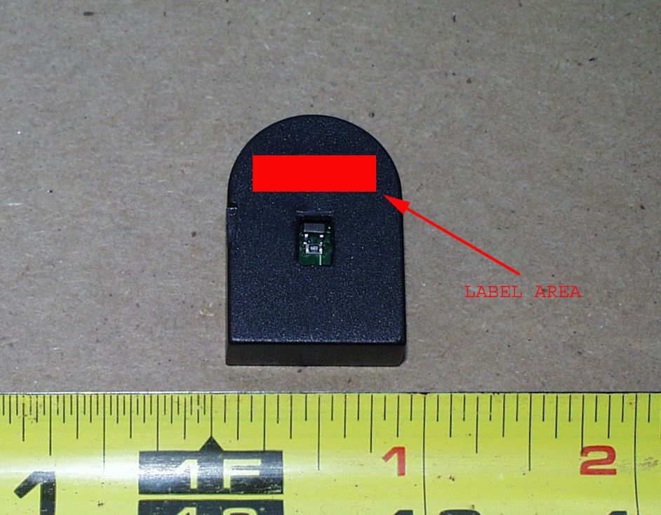
0.500" 0.125" S UU -SHIELD1-1 FCC ID: 4:1 SHIELD1.1 ID LABEL B EVERAGE METRICS 0 AB CD 4321 D C B A 1234 TitleScale Model Rev Date Drawn by Filename Sheet of
Operational Description
Beverage Metrics Operational Description of 418 MHz Transmitter 418 MHz Transmitter: The Shield is a 418 MHz, single frequency, on-off keyed (OOK) type transmitter. Its architecture and design are based on a negative feedback colpitts type oscillator which is frequency stabilized by a surface acoustic wave (SAW) resonator. The unit is powered by one 3 volt lithium battery and consumes close to 5 mA of current. The system modulation is accomplished by the turning on and off of the transmitter with a microprocessor running at 5 MHz. The data rate of the modulation is ca. 1200 BPS. There is either a pushbutton or hall-effect sensor on the transmitter which when engaged activates the unit. The antenna type employed is a helical loop which is permanently mounted to the transmitter’s PCB. Beverage Metrics Transmission Scheme May 06, ‘04 Preamble on all transmissions = 32 pulses of 416 uSec on and 416 uSec off. De-squelch pulse = 1160 uSec. Total duration = 192.5 mSec. Data packets are sent in 66% - 33 % format where a digital “One” is 66% on and 33% off. A “Zero” is 33 % on and 66% off. The following times are measured at the output of the microprocessor. A “one” is on for 610 uSec and off for 320 uSec typically. A “Zero” is on for 320 uSec and off for 610 uSec. Activated Transmission: Pour Activation Packet Second Packet Third Packet Delayed 1 to 6 seconds Delay 15 – 20 seconds Delay 30-35 seconds After pour activation after first packet after second packet Retransmit Packet lengths: * Please note worst case was submitted. Packet size varies depending on the number of pours that haven’t been transmitted a total of 3 times. Data packet for 1 pour = 119 mSec. Data packet for 2 pours = 161 mSec. Data packet for 3 pours = 202 mSec. Data packet for 4 pours = 244 mSec. System integrity transmissions begin 4 hours after last pour and every 4 hours from then on, to let the system know that the device is on line and functioning properly. They employ the same format as a single packet transmission but pour data is 0.
Test Report
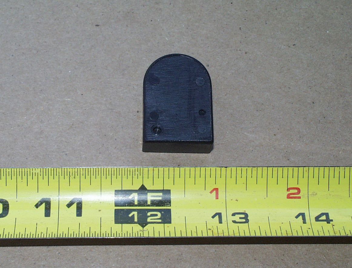
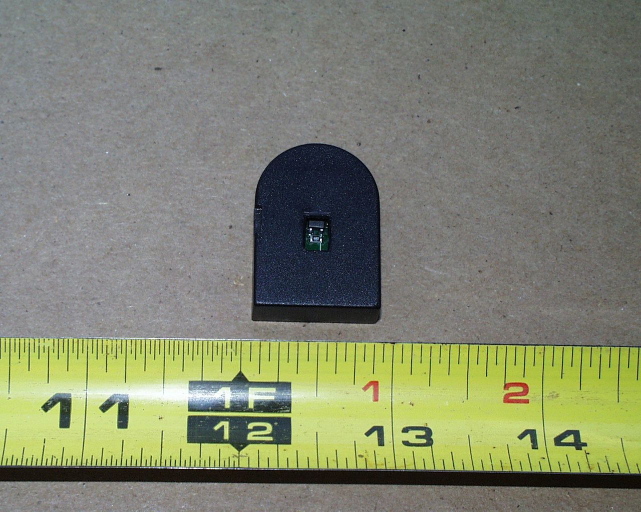
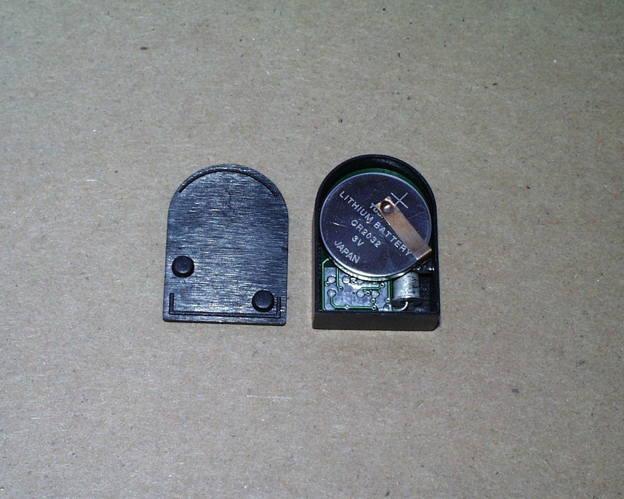
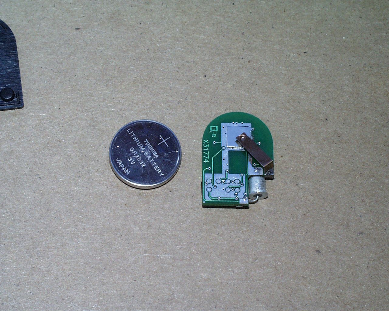
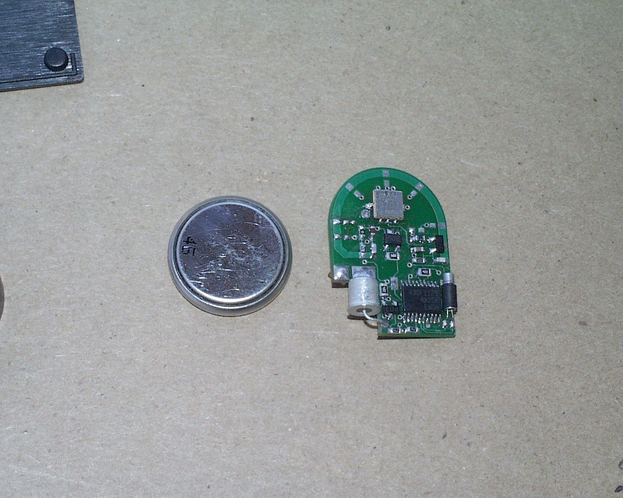
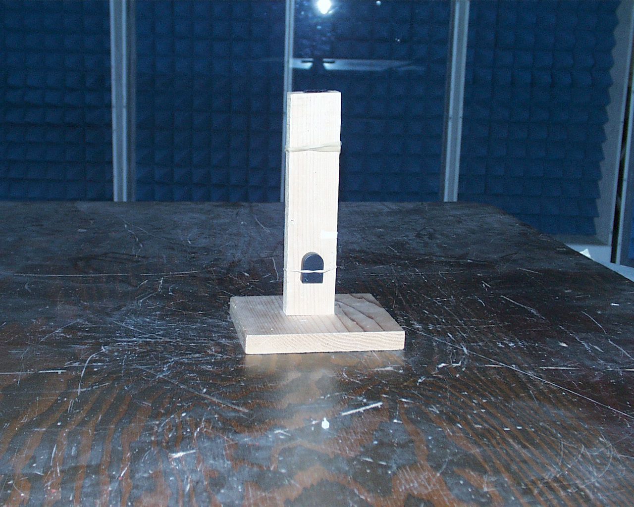
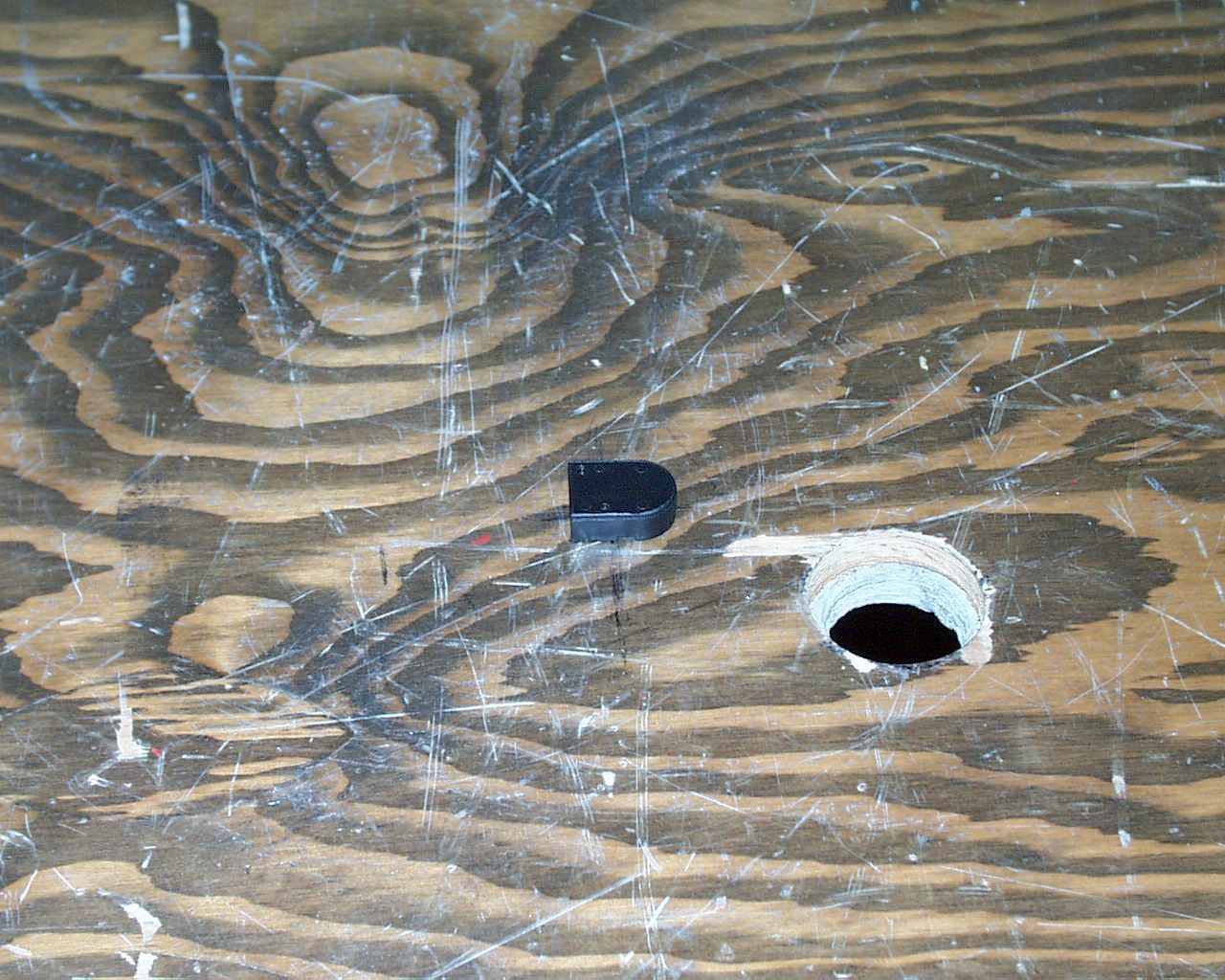
SRN-SHIELD1-1 BOTTLE METRICS Test Report of an Intentional Radiator for Certification under Part 15 of the FCC rules DUT: Control Transmitter FCC ID SRN-SHIELD1-1 Section 15.231 Date: 08-December-2004 Manufacturer: Bottle Metrics, Inc. 3001 Bridgeway, #334 Sausalito, CA 94965 (415) 717-4244 Prepared by: Control Design & Testing, Inc. 6010 Red Fox Drive Spotsylvania, VA 22553 (540) 582-2826 1 SRN-SHIELD1-1 BOTTLE METRICS A. DEVICE UNDER TEST The product is a transmitter used as an inventory control device that tracks the tilting of a bottle. This device is designed to be attached to the neck of a bottle and indicate the when the bottle is tilted. The product is designed to operate under the provisions of Part 15.231 of the FCC rules in the United States and RSS-210 in Canada. The device is self contained in a sonically welded, plastic enclosure and is powered by an internal 3 volt lithium coin cell. There is no provision to use an external power source. The frequency of operation is 418.00 MHz. nominal. The modulation mode is on/off keying using a proprietary pulse width scheme. In normal operation, this device is programmed to transmit three packets, spaced over a period of 35ms, upon a “tilt event” and again one packet every four hours to insure system integrity. The rf circuit is a modified colpitts oscillator using a SAW resonator as the frequency determining element. The radiating element is a track antenna printed on the circuit board. There is no provision to connect an external antenna. The test samples were provided in prototype plastic enclosures. The FCC ID label will be placed on the plastic cover as shown in the “label area” photograph. B. MEASUREMENT PROCEDURE: RADIATED EMISSIONS Radiated emissions testing of this device was conducted at the Carl T. Jones test facility located in Springfield, Virginia. FCC Site #90490 The field strength measurements were conducted according to the procedures set forth in ANSI C63.4 (1992). The device under test was placed on a rotating turntable 0.8 meters high, centered at 3 meters distant from the measurement antenna. The device was tested in two major planes. Two sets of measurements were taken. The device was placed in the center of the turntable and tested in both positions shown in the test setup photographs. For the purpose of radiated emissions testing, one of the test samples was specially programmed to transmit typical packets, at an accelerated rate, continuously. The occupied bandwidth plot below (Plot 1) was captured using this signal. 2 SRN-SHIELD1-1 BOTTLE METRICS Plot 1 3 SRN-SHIELD1-1 BOTTLE METRICS The field strength measurements were taken using an HP8596E spectrum analyzer, an EMCO 3121C dipole set, an EMCO 3115 double ridge guide horn and an Avantek UJ210 preamp. The device was scanned from 30 MHz. to 5 GHz. and all emissions were noted. In this case, the only emissions detected were those harmonically related to the fundamental transmit frequency. At each detected emission frequency, the device was measured by rotating the turntable and adjusting the antenna height over a range of 1 to 4 meters to obtain the maximum output level. This procedure was performed with both horizontal and vertical antenna polarizations for both of the test positions shown in the setup photos. The peak reading for each frequency was recorded in the fourth column in the tables below. Measurements taken for weak emissions were performed by reducing the distance from the measurement antenna to 1 meter and factoring –9.54dB into the calculation. This method was used to measure the 8 th and 9 th harmonics. CLIENT: BOTTLE METRICSFCC ID: SRN-SHIELD1-1 EUT: CONTROL TRANSMITTER PART 15.231DATE: 07-DEC-04 Ant. Polar. H/V 418.101H22.7-54.065.96053306910333 836.202H30.2-78.385.98734431033 1254.303H27.6-83.525.93581821033 1672.404H29.3-89.015.9231117500 2090.505V31.0-93.545.9167851033 2508.606V32.2-95.155.9159811033 2926.707H33.6-98.225.9132671033 3344.808V34.9-100.165.9122621033 3762.909V36.1-106.435.96835500 Table 1 RADIATED EMISSIONS DATA Frequency In MHz. Peak Power uV/m@3m Peak reading dBm Ant. Factor dB ANTENNA: DIPOLES/DRG HORN Duty Cycle -dB FCC Limit uV/m@3m Corrected Power uV/m@3m 4 SRN-SHIELD1-1 BOTTLE METRICS C. DUTY CYCLE AND INTERVAL CALCULATIONS The occupied bandwidth and duty cycle measurements were made using an HP8594E spectrum analyzer and plotted with an HP7475A pen plotter. The computation for the duty cycle correction factor in column five in Table 1 is derived from the manufacture’s description of the data scheme and is verified by plots 2 through 5. The code format for this device is a pulse width scheme that comprises 32 bits of preamble at 50% duty cycle, a de-squelch pulse at 1.16ms and data of evenly distributed “one’s and “zero’s” at a 33/66 ratio. Measurements of pulse widths have been taken to insure worst case. The worst case transmission for this device in any 100ms period is given in the calculation below. The correction factor is given by: Desquelch 1.16ms Data and Preamble 98.84ms ÷ 2 = 49.42ms 50.58ms 20log(50.58ms./100ms.) = -5.92dB. As provided in Part 15.35 of the FCC rules, a correction factor of –5.9 dB is used for the calculations on the data sheet above. 5 SRN-SHIELD1-1 BOTTLE METRICS Plot 2 6 SRN-SHIELD1-1 BOTTLE METRICS Plot 3 7 SRN-SHIELD1-1 BOTTLE METRICS Plot 4 8 SRN-SHIELD1-1 BOTTLE METRICS Plot 5 9
Contact Information
Applicant
Nancy Moore(CFO)
Test Firm
Carl T. Jones CorporationCarl Jones
Technical Specifications
| # | Rule Parts | Frequency Range | Power Output |
|---|---|---|---|
| 1 | 15.231 | 417.75 MHz - 418.25 MHz | - |