SVHBAROSTIMIPG1Model 2100 Barostim IPG
CVRx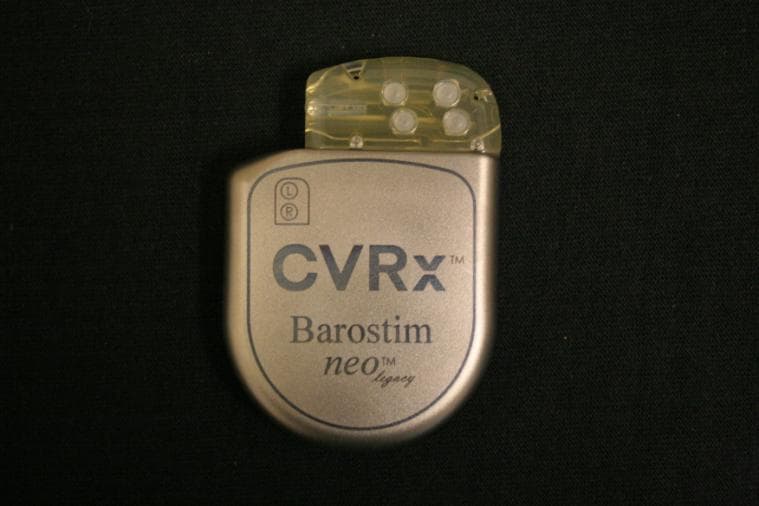
Click to zoom
Application Details
- Equipment Class
- TNT - Licensed Non-Broadcast Transmitter Worn on Body
- Date of Grant
- Dec 11, 2013
- Application Purpose
- Original Equipment
- Date of Application
- Oct 21, 2013
- Equipment Note
- Model 2100 Barostim IPG
- Frequency Range
- 402.00000000 - 405.00000000
- Company
- CVRx
- Country
- United States
Documents & Files
Document Text
Text extracted from the exhibit documents filed with the FCC. Open a document above to read the original.
Users Manual
CAUTION: Federal law restricts this device to sale by or on the order of a physician. Humanitarian Device. Authorized by Federal law for use in the treatment of resistant hypertensive patients implanted with the Rheos CSL leads. The effectiveness of this device has not been demonstrated. TABLE OF CONTENTS BAROSTIM NEO LEGACY REFERENCE GUIDE i 1 SYSTEM DESCRIPTION ........................................................................................................................1-1 Implantable Pulse Generator (IPG) ....................................................................................................................1-1 CVRx Programmer System Model 9010 ...........................................................................................................1-2 Programmer Software...................................................................................................................................1-2 Programmer Interface ...................................................................................................................................1-2 Optional Accessories for Use with the Neo Legacy System..............................................................................1-3 CVRx Magnet ..............................................................................................................................................1-3 CVRx Accessory Kit ....................................................................................................................................1-3 CSL Repair Kit Model 5010 ........................................................................................................................1-3 2 SYMBOLS AND DEFINITIONS ..............................................................................................................2-1 3 INDICATIONS .........................................................................................................................................3-1 4 WARNINGS AND PRECAUTIONS ........................................................................................................4-1 Warnings ......................................................................................................................................................4-1 Precautions ...................................................................................................................................................4-1 Implantable Pulse Generator ..............................................................................................................................4-2 Warnings ......................................................................................................................................................4-2 Precautions ...................................................................................................................................................4-2 Carotid Sinus Lead ............................................................................................................................................4-3 Warnings ......................................................................................................................................................4-3 Precautions ...................................................................................................................................................4-3 CVRx Programmer System ...............................................................................................................................4-3 Warning ........................................................................................................................................................4-3 Precautions ...................................................................................................................................................4-3 CVRx Magnet ....................................................................................................................................................4-4 Precaution .....................................................................................................................................................4-4 Accessory Kit ....................................................................................................................................................4-4 Warnings ......................................................................................................................................................4-4 Precautions ...................................................................................................................................................4-4 5 CLINICAL SUMMARY AND ADVERSE EVENTS .................................................................................5-1 6 PHYSICIAN TRAINING AND EXPERIENCE .........................................................................................6-1 7 NEO LEGACY SYSTEM PREPARATION .............................................................................................7-1 How Supplied ....................................................................................................................................................7-1 Implantable Pulse Generator ........................................................................................................................7-1 Programmer System .....................................................................................................................................7-1 Inspection Prior to Use ......................................................................................................................................7-1 Implantable Pulse Generator ........................................................................................................................7-1 Materials Recommended for Implantation and/or Explantation .............................................…
Text truncated - open the document above for the full version.
Cover Letter(s)
MEMO CVRx, INC. PAGE 1 OF 3 To: Federal Communications Commission Office of Engineering and Technology 7435 Oakland Mills Road Columbia, MD 21046 From: Russell Anderson CVRx Inc 9201 West Broadway Suite 650 Minneapolis MN 55445 Date: November 14, 2013 Subject: Response to FCC Correspondence Reference Number: 44623 Dear Sir or Madam: CVRx has received and acknowledges the correspondence referenced below from the FCC (Correspondence Reference Number: 44623, for Form 731 Confirmation Number: EA964542), and is providing this response. The response from CVRx is listed below each item sent by the FCC. Also included in our return correspondence are the following documents: 1. CVRx Request for Confidentiality for FCC ID: SVHBAROSTIMIPG1 (to address items #2 below). 2. RF Module Equivalency between CVRx IPG Model 2101 and Models 2100/ 2102 (to address item #3 below). 3. Report Number: 100511823MIN-001 Rev 1.1 (to address items #5 - #7 below). From the FCC: Re: FCC ID: SVHBAROSTIMIPG1 Applicant: CVRx Correspondence Reference Number: 44623 Form 731 Confirmation Number: EA964542 Date of Original E-mail: 11/07/2013 MEMO CVRx, INC. PAGE 2 OF 3 Upon initial review of your equipment authorization application, the following points were noted: 1) Intended maximum output power does not appear to be noted within the application. Please identify the maximum output power desired for this device. Response: The maximum radiated output power measured for this device is -39.5dbm, or 0.112 microwatts, or 0.000000112Watts. 2) The exhibit titled "Request for Confidentiality" is not signed. Please sign and update as necessary. Response: A signed and updated "Request for Confidentiality" is now submitted with this response. 3) The exhibit titled "Model 2100 Model 2102 Equivalency", submitted as part of the test report, indicates that models 2100 and 2102 are exactly the same from an RF perspective. The exhibit titled "Report Summary", submitted as part of the exposure evaluation, indicates that models 2100 and 2102 are identical to the 2101 except for a RF difference. This RF difference between the 2101 and the other two models are described as an updated telemetry module. Please submit updated documentation further discussing this difference. Such documentation may include internal photos showing the telemetry module, discussion of how the telemetry module impacts the output signal, difference in total output power ratings, and the like. Furthermore, please ensure that all exhibits consistently show all model numbers for which their data is applicable. Response: An “RF Module Equivalency between CVRx IPG Model 2101 and Models 2100/ 2102” memo is submitted with this response. To add clarification; the original submission did not, but should have, explained that the exhibits which refer to the Model 2100 are also applicable to the Model 2102. The two models differ only by a single (fuse) component. The RF performance of these two models is identical. All of the submitted exhibits that referenced only the Model 2100 model are applicable to both the Model 2100 and Model 2102 models. 4) The submitted Form 731 indicates that this device is not part of a system that operates with, or is marketed with, another device that requires an equipment authorization. However, the exhibit "CVRx System Reference Guide" indicates that an associated base-station will be part of this system and will require equipment authorization. Please update the Form 731 as appropriate. Response: The associated base-station is part of this system and we agree this will require equipment authorization. The testing is complete, and the report for the base station is being MEMO CVRx, INC. PAGE 3 OF 3 prepared for submission by a qualified TCB. The FCCID for the base station is SVHBAROSTIMPGM1. 5) Throughout the submitted documentation, this device is referred to as MICS. The term MICS is now obsolete for the purposes of FCC authorizations and operations. Although revision is not required for this filing, for all future filings for similar devices, pleas ensure to use descriptions consistent with the rules in effect at the time of the applications submissions; i.e. in this case being MedRadio. Response: The Test Report has been updated to reflect the new MedRadio label references, and is submitted in this response. CVRx appreciates this feedback, and will also note this in future applications. 6) The exhibit titled "Test Report" references 47 CFR 95.628. However, 95.628 applies only to MedRadio transmitters in the 413-419 MHz, 426-432 MHz, 438-444 MHz, and 451-457 MHz bands. Please update your test specification references to reflect changes to 47 CFR since the time this test was conducted (17OCT2011). The most recent CFR rules can be found at www.ecfr.gov. Response: The Test Report has been updated to reflect the new test specification references and is submitted in this response. 7) The exhibit titled "Test Report" has identified several part 95 rule sections used for compliance demonstration. Please also note that 2.1033(c)(14) requires demonstrating compliance for 2.1046 to 2.1057. Per 2.911(b), compliance must be documented for both 2.1033(c)(14) and part 95. Please revise this document accordingly. Response: The Test Report has been updated to reflect the new test specification references and is submitted in this response.
Cover Letter(s)
9201 West Broadway Avenue, Suite 650, Minneapolis, MN 55445 Phone (763) 416-2840 Fax (763) 416-2841 www.cvrx.com PAGE 1 OF 2 To: Federal Communications Commission Equipment Authorization Branch 7435 Oakland Mills Road Columbia, MD 21046 From: CVRx Inc 9201 West Broadway Suite 650 Minneapolis MN 55445 Date: November 25, 2013 Subject: CVRx Request for Confidentiality for FCC ID: SVHBAROSTIMIPG1 Dear Sir or Madam: CVRx respectfully requests specific information to be held from public inspection. Per the FCC Commission Rules Title 47 Part 0, Subpart C Section 0.457 and Section 0.459, CVRx supplies the following to address the reasons for withholding the materials from inspection: (1) identification of the specific information for which confidential treatment is sought; Schematic Diagrams Model 2100 Parts List Model 2100 Block Diagram Model 2100 Internal Photographs Model 2100 Operational Description Model 2100 (2) identification of the Commission proceeding in which the information was submitted or a description of the circumstances giving rise to the submission: The application for certification is for FCC ID: SVHBAROSTIMIPG1 implantable medical device. (3) explanation of the degree to which the information is commercial or financial, or contains a trade secret or is privileged: The information described above in item (1) is used in a sealed implantable medical device and contains information that is considered highly confidential, secret and proprietary. Many years of research and development, and efforts to maintain the confidential nature of these items have preceded this submission. (4) explanation of the degree to which the information concerns a service that is subject to competition: The implantable medical device market is highly competitive and is comprised of several companies that are much larger than CVRx. 9201 West Broadway Avenue, Suite 650, Minneapolis, MN 55445 Phone (763) 416-2840 Fax (763) 416-2841 www.cvrx.com PAGE 2 OF 2 (5) explanation of how disclosure of the information could result in substantial competitive harm: This disclosure contains proprietary and trade secret information regarding system architecture, hardware implementation, vendor selection, and the design and manufacturing method. Release of this information would allow competitors unwanted access to years of development effort spent at CVRx. (6) identification of any measures taken by the submitting party to prevent unauthorized disclosure: The information disclosed is not shown or discussed with the public through any type of publication or presentation. All of these documents are classified as confidential and kept under documentation control to protect access. (7) identification of whether the information is available to the public and the extent of any previous disclosure of the information to third parties: The information disclosed has never been shown to the public, and only shared with third parties through a legally binding non-disclosure agreement. The only limited disclosure to third parties has been specific to address confidential development efforts. (8) justification of the period during which the submitting party asserts that material should not be available for public disclosure: CVRx requests the information disclosed not be made public for a term of ten years. The information disclosed is for a new platform architecture, and future product families will be based on this design. The communication architecture demands protection from unauthorized and unwanted viewing to avoid the misuse of the telemetry link. (9) any other information that the party seeking confidential treatment believes may be useful in assessing whether its request for confidentiality should be granted: This is an implantable medical device which offers therapy to patients needing chronic treatment. Privacy and confidentiality to the inner workings of this device is required to ensure ongoing safety and security. Regards, Russell Anderson Technical Fellow CVRx, Inc. Email: [email protected] Phone: 763-416-2332 Fax: 763-416-8400
External Photos
CVRx, INC. PAGE 1 OF 1 To: Certification File From: Russell Anderson Date: September 16, 2013 Subject: External Photos for Model 2100 Implantable Pulse Generator CVRx Model 2100 Implantable Pulse Generator external photos
ID Label/Location Info
CVRx, INC. PAGE 1 OF 2 To: Federal Communications Commission Laboratory Division 7435 Oakland Mills Road Columbia, MD 21046 From: CVRx Inc 9201 West Broadway Suite 650 Minneapolis MN 55445 Date: October 14, 2013 Subject: FCC required labeling for CVRx Model 2100 IPG: FCCID:SVHBAROSTIMIPG1 Dear Sir or Madam, This device is for a human body implant application and the label for the FCCID is placed in the following locations: The CVRx Model 2100 IPG package label The Neo-Legacy Reference Guide (User Manual) in section 15, along with the corresponding FCC required statements (attached below for reference) Should you have any questions regarding this letter, please feel free to contact me. Russell Anderson Technical Fellow CVRx, Inc. Email: [email protected] Office phone: 763-416-2332 Fax: 763-416-8400 CVRx, INC. PAGE 2 OF 2
RF Exposure Info
PAGE 1 OF 3 R R R E E E P P P O O O R R R T T T MODEL 2100 AND 2102 IPG SAR ANALYSIS REPORT REV DATE: 12/31/11 AUTHOR: DAN KOLLMANN REVISION: REV. A REV. A MODEL 2100 AND 2102 IPG SAR ANALYSIS REPORT PAGE 2 OF 3 TABLE OF CONTENTS 1. INTRODUCTION ..................................................................................................................................................................... 3 1.1. Purpose / Scope ................................................................................................................................................................ 3 2. DEFINITIONS, ACRONYMS, AND ABBREVIATIONS .................................................................................................... 3 3. SUMMARY ............................................................................................................................................................................... 3 4. APPENDICES ........................................................................................................................................................................... 3 REV. A MODEL 2100 AND 2102 IPG SAR ANALYSIS REPORT PAGE 3 OF 3 1. INTRODUCTION 1.1. Purpose / Scope This document provides the SAR simulation results applicable to the Model 2100 and 2102 IPGs to demonstrate compliance to radio frequency exposure limits as defined in 47 CFR Part 1, section 1.1307 and in 47 CFR Part 2, section 2.1093 . The results are based on simulation of a Model 2101 IPG which has identical enclosure, header, and antenna. 2. DEFINITIONS, ACRONYMS, AND ABBREVIATIONS Acronym/ Abbreviation Definition IPG Implantable Pulse Generator SAR Specific Absorption Rate 3. SUMMARY The Model 2100 and 2102 IPGs are identical to the Model 2101 IPG from an RF perspective. The Model 2101 IPG simulation report included in Appendix A is applicable to the Model 2100 and 2102 IPGs since they are derived from the Model 2101 IPG with identical enclosure, header, and antenna. The only RF difference from the Model 2101 to the Models 2100 and 2102 is the use of an updated RF telemetry module. This difference affects the transmitter power level at the antenna input and scales the SAR values, but otherwise has no affect on the simulation model. The Model 2100 and 2102 transmitter power measured when using the antenna impedance from the Appendix A report ranged from -2.8dBm to -2.5dBm. The 0dBm transmitter power level used in the Appendix A report exceeds these measurements and therefore the SAR values for the Model 2100 and 2102 IPGs will be lower than the values listed in Appendix A and are therefore passing as well. 4. APPENDICES Appendix No. Document Title Appendix A CVRx IPG Model 2101 SAR Report
RF Exposure Info
1 CVRx IPG Model 2101 SAR Report Prepared By: James F. Stack, Jr. Remcom, Inc. 20 April 2011 2 1. Introduction This SAR computation modeling is performed to show compliance to radio frequency exposure limits as defined in 47 CFR Part 1, section 1.1307 and in 47 CFR Part 2, section 2.1093. The usage of the equipment is uncontrolled, therefore the limit for partial-body SAR is 1.6 W/kg, as averaged over any 1 g cubical tissue volume. The whole-body limit for average SAR is 0.08 W/kg. 2. Scope This report scope illustrates compliance as required in 47 CFR Part 95, section 95.603(f) for the CVRx IPG Model 2101 SAR Report. 3. Summary The maximum SAR values were computed and listed in Table 1. Who le-body average SAR 4.9e-5 W/kg Partial-body maximum 1g average SAR 0.035 W/kg Table 1 Computed SAR levels summary 4. Method and Simulation Parameters XFdtd version 7.2.0.4, developed by Remcom, Inc. (1), was used for the simulations. The software uses the Finite Difference Time-Domain (FDTD) method for electromagnetic calculation, as described in (2). 4.1. Model and Material Details A CAD model of the parts relevant to antenna operation of the implanted device was imported into XFdtd as shown in Figure 1. The device was situated within a bio logical flat phantom that was 445.788 mm long (in the y-direction), 297.192 mm wide (in the x-direction), and 150 mm in depth (z-direction), as shown in Figure 2. The dimensions of the flat phantom were set based on specifications as defined in section D.9.2 (Experimental Body Phantom) of (3). 3 Figure 1 Device CAD file as displayed in XFdtd 4 Figure 2 Device placed in flat phantom with XYZ coordinate axis shown In order to provide a worst-case SAR analysis (with no losses in the conducting elements as would be seen in a real metal conductor), Perfect Electrical Conductor (PEC) was used on all conductive parts of the device. All dielectric materials were modeled as lossless. The flat phantom was modeled using electrical parameters as described in Appendix C of (4). Since the device is intended to be implanted into a human torso, the tissue dielectric properties for the 5 body were used. Since the chart in (4) lists properties for specified frequencies, a linear interpolation was performed to generate property values for the target frequency of 403.5 MHz. The dielectric material parameters used are listed in Table 2. Material Relative Permittivity Conductivity Density PEC 0 Infinite n/a Header Dielectric 3.7 0 n/a Flat Phantom 57.165 0.9338 S/m 1,000 kg/m^3 Table 2 Dielectric properties of materials used in the simulations 4.2. Gridding Parameters The user must define the grid size according to limits determined by the highest frequency to be considered as well as the geometry of the object being simulated. At an operating frequency of 403.5 MHz, the largest cell size supported is 74 mm. This maximum size, however, was not used as it would not adequately resolve the geometry of the objects in the simulation. The maximum cell size used in this simulation was 2 mm. Since the software will support multiple cell sizes within a single project, a cell size of 0.35 mm was chosen for the cells comprising the device, and a finer cell size of 0.17 mm for the cells that make up the radiating element. Additionally, fixed points were used so that grid lines were placed along edges and other important parts of the geometry so that the size of the object was adequately represented by the cells. The grid sizes used are summarized in Table 3. Figure 3 and Figure 4 show the grid lines of the front of the device. Figure 5 and Figure 6 show the grid lines of the side of the device. Grid Region Cell Size Electrical Size (in freespace) Base cell size 2 mm 0.00269*λ Device cell size 0.35 mm 4.7297e-4*λ Antenna cell size 0.17 mm 2.2973e-4*λ Table 3 Summary of cell sizes used in the simulations 6 Figure 3 FDTD grid lines showing front of device 7 Figure 4 FDTD grid lines showing front of device, antenna closeup Figure 5 FDTD grid lines showing side of device 8 Figure 6 FDTD grid lines showing side of device, closeup of header The base FDTD grid sizes listed above were chosen using experience and best practices for modeling such devices. The grid sizes chosen were validated by running additional simulations using sizes 0.5 and then 0.25 times the device cell sizes and verifying that the results remained the same to within a small tolerance. 4.3. Description of Simulated Device The implantable medical device that was simulated is shown in Figure 1. The CAD model was used for the simulation and thus was representative of the device. All relevant parts of the device, including the casing, header, loop antenna, antenna leads, and other objects were included in the model. 4.4. Input Power and Source Excitation In order to calculate the worst-case SAR values, the waveform used to excite the antenna was a 1 V peak-to-peak sinusoid (therefore 100% duty cycle) at 403.5 MHz. An initial simulation found the input impedance of the antenna (while in the device and embedded in the flat phantom material) to be 63 + j341.7 Ω. An impedance-matching network was then used to feed the device. The components comprising the voltage source and matching network were fed between the leads to the loop antenna, as shown in Figure 7. This matching circuit was used solely for the 9 purpose of ensuring that a meaningful amount of energy was introduced into the simulation space for later scaling. After the simulation was completed, the available power was scaled within the software to 1 mW (0 dBm), with the SAR values automatically scaled accordingly. This scaled power represents the maximum amount of power that could be delivered to the antenna assuming a perfect impedance match. Figure 7 Voltage source (green cone) and matching network (green cylinders) used to feed the device 5. Wost-Case SAR Analysis / Results The device was modeled in the middle of the frequency band since there was little expected difference betw…
Text truncated - open the document above for the full version.
RF Exposure Info
MEMO CVRx, INC. PAGE 1 OF 2 To: Federal Communications Commission Office of Engineering and Technology 7435 Oakland Mills Road Columbia, MD 21046 From: Russell Anderson CVRx Inc 9201 West Broadway Suite 650 Minneapolis MN 55445 Date: November 14, 2013 Subject: RF Module Equivalency between CVRx IPG Model 2101 and Models 2100/ 2102 Dear Sir or Madam: CVRx submits this memo in response to item #3 of Correspondence Reference Number: 44623, cited in part below, for reference: “The exhibit titled "Report Summary", submitted as part of the exposure evaluation, indicates that models 2100 and 2102 are identical to the 2101 except for a RF difference. This RF difference between the 2101 and the other two models is described as an updated telemetry module. Please submit updated documentation further discussing this difference.” Response: The Model 2101 IPG contains a commercially available RF module, and the Model 2100 and 2102 IPG’s contain an updated version of this module (which is specified by name as U4 in the Parts List submitted with the original application). The items below identify changes between these RF modules. MEMO CVRx, INC. PAGE 2 OF 2 1. The new RF module has improved on-chip matching capacitor banks to allow more antenna match settings to the user. 2. The new RF module has reduced spurious emissions outside the MedRadio band. 3. The new RF module has improved receive sensitivity and dynamic range of the 2.4GHz receiver. 4. The new RF module is backward compatible with the previous module used in the Model 2101 IPG. It is a drop in replacement from a hardware point of view (identical physical size, pad positions and functions). In all other ways, the RF modules are identical. Although the on-chip capacitor banks can improve efficiency and allow for a better antenna match, the module power output remains the same. There is no impact to the module RF output frequency, or RF output power ratings. The out-of band performance with the newer module is improved. The new RF module has identical circuitry for the 400MHz transmitter section in terms of the output circuit, frequency generation circuit, and overall topology compared to the previous module. The package size and material are identical for both modules.
Test Report
TEST REPORT Report Number: 100511823MIN-001 Rev 1.1 Project Number: G100511823 Testing performed on the 2102 IPG FCC ID: SVHBAROSTIMIPG1 Industry Canada ID: 9464A-IPG210A to 47 CFR Part 95 Subpart I:2013 RSS- 243, Issue 3, November 2010 47 CFR, Part 15:2013, §15.109, Class B CVRx Inc. Test Performed by: Test Authorized by: Intertek Testing Services NA, Inc. 7250 Hudson Blvd., Suite 100 Oakdale, MN 55128 USA CVRx Inc. 9201 West Broadway Avenue, Suite 650 Minneapolis, MN 55445 Prepared by: Date: November 8, 2013 Uri Spector Reviewed by: Date: November 8, 2013 Norman Shpilsher This report is for the exclusive use of Intertek's Client and is provided pursuant to the agreement between Intertek and its Client. Intertek's responsibility and liability are limited to the terms and conditions of the agreement. Intertek assumes no liability to any party, other than to the Client in accordance with the agreement, for any loss, expense or damage occasioned by the use of this report. Only the Client is authorized to copy or distribute this report and then only in its entirety. Any use of the Intertek name or one of its marks for the sale or advertisement of the tested material, product or service must first be approved in writing by Intertek. The observations and test results in this report are relevant only to the sample tested. This report by itself does not imply that the material, product, or service is or has ever been under an Intertek certification program. This report must not be used to claim product endorsement by A2LA, NIST nor any other agency of the U.S. Government. EMC Report No: 100511823MIN-001 Rev 1.1 FCC ID: SVHBAROSTIMIPG1 IC ID:9464-IPG210A Page 2 of 26 TABLE OF CONTENTS 1.0 GENERAL DESCRIPTION..........................................................................................................3 1.1 Product Description; Test Facility......................................................................................4 1.3 Environmental conditions ..................................................................................................5 1.4 Measurement uncertainty..................................................................................................6 1.5 Field Strength Calculation .................................................................................................6 2.0 TEST SUMMARY..........................................................................................................................7 3.0 TEST CONDITIONS AND RESULT…
Text truncated - open the document above for the full version.
Contact Information
Applicant
Bart Carey(Director Device Engineering)
Technical Contact
CVRx IncorporatedRussell Anderson
[email protected]763 416 2332
9201 West Broadway · Minneapolis, Minnesota · United States
Non-Technical Contact
CVRx IncorporatedJoe DuPay
[email protected]7643 416 2337
Test Firm
Intertek Testing Services NA, Inc.Andrew Waytulonis
Technical Specifications
| # | Rule Parts | Frequency Range | Power Output | Emission | Tolerance |
|---|---|---|---|---|---|
| 1 | 95I | 402 MHz - 405 MHz | 0.10 µW | 234KFID | 3.7000000000 ppm |