SVNITARD024MAHMulti Target Bayonet Radar
Zhejiang Dahua Vision Technology Co., Ltd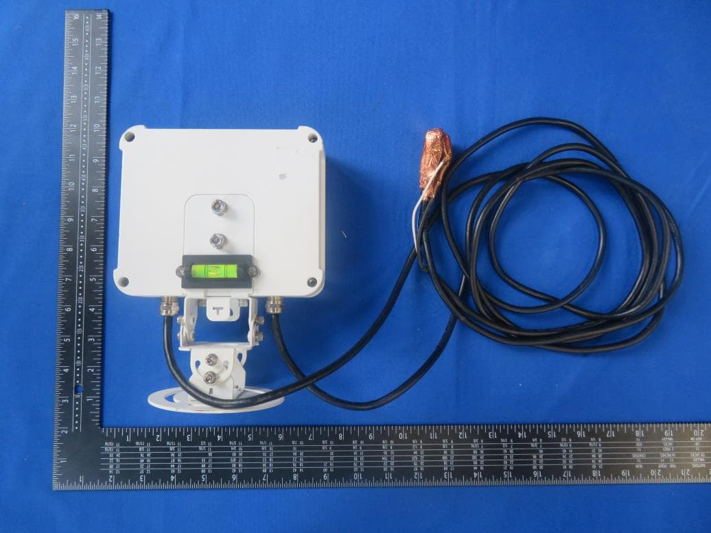
Click to zoom
Application Details
- Equipment Class
- DXX - Part 15 Low Power Communication Device Transmitter
- Date of Grant
- Jul 26, 2020
- Application Purpose
- Original Equipment
- Date of Application
- Jul 23, 2020
- Equipment Note
- Multi Target Bayonet Radar
- Frequency Range
- 24150.00000000 - 24150.00000000
- Country
- China
Documents & Files
Document Text
Text extracted from the exhibit documents filed with the FCC. Open a document above to read the original.
Users Manual
Multilane Radar Detector User’s Manual V1.0.0 V1.0.0 ZHEJIANG DAHUA VISION TECHNOLOGY CO., LTD. ZHEJIANG DAHUA VISION TECHNOLOGY CO., LTD. User’s Manual I Foreword General This manual introduces the functions and operations of the multilane radar detector (hereinafter referred to as the "Radar"). Model DHI-ITARD-024MA-H Safety Instructions The following categorized signal words with defined meaning might appear in the manual. Signal Words Meaning WARNING Indicates a medium or low potential hazard which, if not avoided, could result in slight or moderate injury. CAUTION Indicates a potential risk which, if not avoided, could result in property damage, data loss, lower performance, or unpredictable result. TIPS Provides methods to help you solve a problem or save you time. NOTE Provides additional information as the emphasis and supplement to the text. Revision History Version Revision Content Release Time V1.0.0 First release. July 2020 About the Manual The manual is for reference only. If there is inconsistency between the manual and the actual product, the actual product shall prevail. We are not liable for any loss caused by the operations that do not comply with the manual. The manual would be updated according to the latest laws and regulations of related jurisdictions. For detailed information, refer to the paper manual, CD-ROM, QR code or our official website. If there is inconsistency between paper manual and the electronic version, the electronic version shall prevail. All the designs and software are subject to change without prior written notice. The product updates might cause some differences between the actual product and the manual. Please contact the customer service for the latest program and supplementary documentation. User’s Manual II There still might be deviation in technical data, functions and operations description, or errors in print. If there is any doubt or dispute, we reserve the right of final explanation. Upgrade the reader software or try other mainstream reader software if the manual (in PDF format) cannot be opened. All trademarks, registered trademarks and the company names in the manual are the properties of their respective owners. Please visit our website, contact the supplier or customer service if there is any problem occurring when using the device. If there is any uncertainty or controversy, we reserve the right of final explanation. User’s Manual III Important Safeguards and Warnings The Radar is a high-technology product that requires professional operations. Read the user's manual carefully before using the Radar, or contact professionals or technical support if you have any doubts. Specifically: Use high-quality DC power supply to avoid crosstalk from other devices. During storage and use, avoid damage caused by impact or fall. Take appropriate lightning protection measures when using outdoors. The interfaces provided by the radar are not hot-swap interfaces. When connecting, please power off before operation to avoid accidental burnout. The RS–485 and RS–232 interfaces of the Radar are not hot-swap interfaces. Power off the Radar before connecting these interfaces to avoid accidental burnout. User’s Manual IV Table of Contents Foreword .................................................................................................................................................... I Important Safeguards and Warnings .................................................................................................... III 1 Product Introduction ............................................................................................................................. 1 Overview ....................................................................................................................................... 1 1.1 Features ........................................................................................................................................ 1 1.2 Appearance ................................................................................................................................... 1 1.3 2 Cable Connection .................................................................................................................................. 2 3 Installation .............................................................................................................................................. 3 Installation Modes ......................................................................................................................... 3 3.1 Notes to Installation ...................................................................................................................... 3 3.2 3.2.1 Adjusting Elevation Angle of Radar .................................................................................... 3 3.2.2 Adjusting Azimuth Angle of Radar ...................................................................................... 5 4 FAQ ......................................................................................................................................................... 7 Cybersecurity Recommendations ..................................................................................... 8 Appendix 1 User’s Manual 1 1 Product Introduction Overview 1.1 The Radar can be installed above the lane to detect vehicles 15 m–45 m (49.2 ft–147.6 ft) away and cover vehicles of 1–4 lanes. It will send capture signals to the camera when the vehicle approaches the specific position, and also detect the vehicle speed and the lane that the vehicle is driving on. Features 1.2 One single radar covers up to 32 vehicles of 1–4 lanes. Precisely detects speed and position of vehicles when they are 18 m–35 m (59.1 ft– 114.8 ft) away. Flexible to install: Either installed right above the lane or at the side of a lane. Special functions such as illegal lane change, wrong-way driving detection…
Text truncated - open the document above for the full version.
Cover Letter(s)
Confidentiality Request Letter Federal Communications Commission Authorization and Evaluation Division FCC ID: SVNITARD024MAH Confidentiality Request Pursuant to Sections 0.457 and 0.459 of the Commission’s Rules, we hereby request confidential treatment of information accompanying this application as outlined below: 1. Block Diagram 2. Schematics 3. Operational Description The above materials contain trade secrets and proprietary information not customarily released to the public. The public disclosure of these matters might be harmful to the applicant and provide unjustified benefits to its competitors. The applicant understands that pursuant to Rule 0.457, disclosure of this application and all accompanying documentation will not be made before the date of the Grant for this application. Sincerely, _____________ Name: Yolanda chen Position: Manager Date: 2020-05-08
Cover Letter(s)
Declaration of Authorization We Name: Zhejiang Dahua Vision Technology Co., Ltd Address: No.1199, Bin'an Road, Binjiang District, Hangzhou, P.R. China Declare that: Name Representative of agent: Marlin Chen Agent Company name: MRT Technology (Suzhou) Co., Ltd Address: D8 Building, Youxin Industrial Park, No.2 Tian'edang Rd., Wuzhong Economic Development Zone City: Suzhou Country: China is authorized to apply for Certification of the following product(s): Product: Multi Target Bayonet Radar FCC ID: SVNITARD024MAH Model: DHI-ITARD-024MA-H, ITARD-024MA-H Brand: Sincerely, _________________ Name: Yolanda chen Position: Manager Date: 2020-05-08
Cover Letter(s)
Declaration letter For our business issue and marketing requirement, we would like to list different model number as following: Model No.: DHI-ITARD-024MA-H, ITARD-024MA-H Model Difference: All is the same between the two models except the silkscreen printed on the body of product. DHI-ITARD-024MA-H shows Dahua logo, but ITARD-024MA-H is none. _____________________ Name: Yolanda chen Position: Manager Date: 2020-05-08
External Photos
Report No.: 2001RSU036-UE 1 of 1 EUT Photograph (1) EUT Photo (2) EUT Photo
ID Label/Location Info
Label Label Location
Internal Photos
Report No.: 2001RSU036-UE 1 of 5 EUT Photograph (1) EUT Photo (2) EUT Photo Report No.: 2001RSU036-UE (3) EUT Photo (4) EUT Photo Report No.: 2001RSU036-UE (5) EUT Photo (6) EUT Photo Report No.: 2001RSU036-UE (7) EUT Photo (8) EUT Photo Report No.: 2001RSU036-UE (9) EUT Photo (10) EUT Photo (Antenna)
Test Report
MRT Technology (Suzhou) Co., Ltd Report No.: 2001RSU036-U1 Phone: +86-512-66308358 Report Version: V01 Web: www.mrt-cert.com Issue Date: 07-21-2020 Page Number: 1 of 33 FCC ID: SVNITARD024MAH APPLICANT: Zhejiang Dahua Vision Technology Co., Ltd Application Type: Certification Product: Multi Target Bayonet Radar Model No.: DHI-ITARD-024MA-H Serial Model No.: ITARD-024MA-H Brand Name: FCC Classification: Part 15 Low Power Communication Device Transmitter (DXX) FCC Rule Part(s): FCC Part 15C (Section 15.249) Test Procedure(s): ANSI C63.10-2013 Test Date: April 01 ~ July 21, 2020 Reviewed By: ( Kevin Guo ) Approved By: ( Robin Wu ) MEASUREMENT REPORT FCC PART 15.249 The test results relate only to the samples tested. This equipment has been shown to be capable of compliance with the applicable technical standards as indicated in the measurement report and was tested in accordance with the measurement procedures specified in ANSI C63.10-2013. Test results reported herein relate only to the item(s) tested. The test report shall not be reproduced except in full without the written approval of MRT Technology (Suzhou) Co., Ltd. Report No.: 2001RSU036-U1 Page Number: 2 of 33 Revision History Report No. Version Description Issue Date Note 2001RSU036-U1 Rev. 01 Initial Report 07-21-2020 Valid Report No.: 2001RSU036-U1 Page Number: 3 of 33 CONTENTS Description Page 1. INTRODUCTION ..................................................................................................................... 6 1.1. Scope ........................................................................................................................... 6 1.2. MRT Test Location ....................................................................................................... 6 2. PRODUCT INFORMATION ..................................................................................................... 7 2.1. Equipment Description .................................................................................................. 7 2.2. Test Configuration ........................................................................................................ 7 2.3. EMI Suppression Device(s)/Modifications ..................................................................... 7 2.4. Labeling Requirements ................................................................................................. 7 3. DESCRIPTION of TEST .......................................................................................................... 8 3.1. Evaluation Procedure ................................................................................................... 8 3.2. AC Line Conducted Emissions ..................................................................................... 8 3.3. Radiated Emissions ...................................................................................................... 9 4. ANTENNA REQUIREMENTS ................................................................................................ 10 5. TEST EQUIPMENT CALIBRATION DATE ............................................................................. 11 6. MEASUREMENT UNCERTAINTY ......................................................................................... 13 7. TEST RESULT ...................................................................................................................... 14 7.1. Summary .................................................................................................................... 14 7.2. AC Conducted Emissions Measurement ..................................................................... 15 7.2.1. Test Limit ................................................................................................................ 15 7.2.2. Test Setup ............................................................................................................... 15 7.2.3. Test Result .............................................................................................................. 15 7.3. Radiated Emission ...................................................................................................... 16 7.3.1. Test Limit ................................................................................................................ 16 7.3.2. Test Setup ............................................................................................................... 17 7.3.3. Test Result .............................................................................................................. 18 7.4. Radiated Restricted Band Edge Measurement ........................................................... 23 7.4.1. Test Limit ................................................................................................................ 23 7.4.2. Test Setup ............................................................................................................... 24 7.4.3. Test Result .............................................................................................................. 25 7.5. Emission Bandwidth Measurement ............................................................................. 29 7.5.1. Test Limit ................................................................................................................ 29 7.5.2. Test Procedure used ............................................................................................... 29 Report No.: 2001RSU036-U1 Page Number: 4 of 33 7.5.3. Test Setting ............................................................................................................. 29 7.5.4. Test Setup ............................................................................................................... 29 7.5.5. Test Result .............................................................................................................. 30 8. CONCLUSION ................................................................…
Text truncated - open the document above for the full version.
Test Setup Photos
Report No.: 2001RSU036-UT 1 of 3 Test Setup Photograph Description: Radiated Emission Test Setup for Below 1GHz (at 3m) Description: Radiated Emission Test Setup for 1GHz -18GHz (at 3m) Report No.: 2001RSU036-UT Description: Radiated Emission Test Setup for 18GHz ~40GHz (at 3m) Description: Radiated Emission Test Setup for 40GHz ~50GHz (at 1m) Report No.: 2001RSU036-UT Description: Radiated Emission Test Setup for 50GHz ~75GHz (at 1m) Description: Radiated Emission Test Setup for 75GHz ~100GHz (at 0.25m)
Contact Information
Applicant
Yolanda chen
Technical Contact
MRT Technology (Suzhou) Co., LtdMarlin Chen
[email protected]86-512-66308358
D8 Building, Youxin Industrial Park, No.2 · China
Non-Technical Contact
MRT Technology (Suzhou) Co., LtdMarlin Chen
[email protected]86-512-66308358
Test Firm
MRT Technology (Suzhou) Co., Ltd.Mr. Marlin Chen
[email protected]+86-512-66308358
Technical Specifications
| # | Rule Parts | Frequency Range | Power Output |
|---|---|---|---|
| 1 | 15C | 24.15 GHz - 24.15 GHz | - |
Other Applications from Zhejiang Dahua Vision Technology Co., Ltd
SVN-1222GL
Nov 23, 2022Attendance Standalone
Equipment Class
DXX - Part 15 Low Power Communication Device Transmitter
SVN-1222GL-D
Nov 22, 2022Attendance Standalone
Equipment Class
DCD - Part 15 Low Power Transmitter Below 1705 kHz
SVN-VTH8642KMSW
Nov 10, 2022IP Indoor Monitor
Equipment Class
DTS - Digital Transmission System
SVN-VTH8622KMSW
Nov 09, 2022IP Indoor Monitor
Equipment Class
DTS - Digital Transmission System
SVNDH-DS21
Nov 08, 2022Wireless Chime
Equipment Class
DTS - Digital Transmission System