SX4INVEOR-M-BG-CINVEOR M BG C
KOSTAL Industrie Elektrik GmbH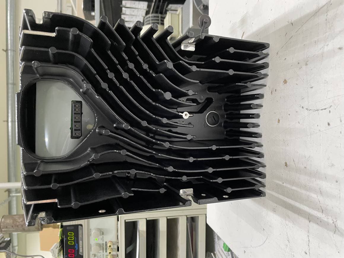
Click to zoom
Application Details
- Equipment Class
- JAD - Part 15 Class A Digital Device
- Date of Grant
- Jan 05, 2023
- Application Purpose
- Original Equipment
- Date of Application
- Jan 05, 2023
- Equipment Note
- INVEOR M BG C
- Country
- Germany
Documents & Files
Document Text
Text extracted from the exhibit documents filed with the FCC. Open a document above to read the original.
Users Manual
2 Operating manual for INVEOR M | DOC02745924-0000 | 2021-08 | V2.30 EN Legal notice KOSTAL Industrie Elektrik GmbH An der Bellmerei 10 58513 Lüdenscheid Germany Tel. +49 (0)2351 16-0 Fax + 49 (0)2351 16-2400 [email protected] Register Court Iserlohn HRB 3924 IMPORTANT NOTE AND LIMITATIONS OF LIAILITY – READ TO UNDERSTAND RIGHTS AND LIMITATIONS A. The information, recommendations, and other content of this Operating Manual (“Content”) is provided as part of the sale of the referenced product and is subject to all limitations and disclaimers that apply to warrantees, remedies, and other provisions of the contract of sale. This includes those found in the General Terms and Conditions of Sale or similar document of the KOSTAL entity seller (“KOSTAL Seller”) that sells the product, as available on its website or provided pursuant to a written request. Content supersedes all previous similar information published by KOSTAL unless specifically provided in writing by a KOSTAL Seller pursuant to a specific inquiry. The Content is that the Content is based on knowledge and experience of KOSTAL Industrie Elektrik GmbH as of the date of initial publication without any obligation to provide updates. For example, industry codes cited in the Content may change. All information provided by a KOSTAL company, regardless of nature or form, is prepared in good faith based upon our experience, mathematical models, and/or scientific models as general information only. However, inquiries on specific prospective product uses that may involve safety risks may be addressed to the KOSTAL central service hotline (see chapter 1 “General information”). B. The Content and all subsequently provided information and advice are provided without additional warranty. For example only, there is no warranty that the Content conforms to any specific national or international industry code or any law or government regulation except as specifically stated. There may be others that provide for more strict safety rules than those on which the Content is based. Mere reference to a specific code or regulation does not constitute a warranty that the Content or product meets the code or standard. In addition, the Content is expressed in general terms for general guidance and must be used in connection with such codes, laws, regulations, best industry practices, and common sense relevant to the specific condition in which KOSTAL product is used. However, errors can occur. The safe use of KOSTAL products is encouraged and users should ask for written clarification if the Content is not clear or adequate for a specific situation. Only written clarifications may be relief upon, and they must be used in connection with the relevant codes, laws, regulations and best industry practices. Any suggestions, projections, or similar information offered in writing, electronically by phone, in person, or in any other form are provided in good faith, but since the functionality and reliability of the products can vary with the application and with the equipment and other components with which they are used, and user skills, ALL WARRANTIES AND REPRESENTATIONS (OTHER THAN THE KOSTAL COMPANY’S NON- ASSIGNABLE STANDARD EXPRESS WRITTEN WARRANTY GIVEN TO DIRECT PURCHASERS FROM THE KOSTAL COMPANY SELLER), SUCH AS, BUT NOT LIMITED TO, ANY IMPLIED WARRANTY OF MERCHANTABILITY FITNESS FOR A PARTICULAR PURPOSE, AND NON-INFRINGEMENT OTHER THAN DIRECT INFRINGEMENT, ARE DISCLAIMED. C. The specific use of the Content and product shall be at the user’s own risk, and the user shall be responsible for observing in connection with the use of the product all national or international proprietary rights, laws and provisions relating to third party intellectual property rights. D. A failure to comply with the Content or any clarifications provided could adversely effect the enforceability of any warranty or remedy. E. This Manual was original prepared as of the month and year noted in the footer. Users of the product can download an updated version of the manual at any time from https://www.kostal-industrie-elektrik.com/INVEOR M drive controllers US Version Exclusion of liability All names, trademarks, product names or other designations used in this manual may be legally protected even if not indicated as such (e.g. as a trademark). KOSTAL assumes no liability for their free usage. The illustrations and texts have been compiled with great care. However, the possibility of errors cannot be ruled out. The compilation is made without any guarantee. General note on gender equality KOSTAL is aware of how language impacts on gender equality and always make an effort to reflect this in documentation. Nevertheless, for the sake of readability we are unable to use non-gender-specific terms throughout and use the masculine form instead. © 2021 KOSTAL Industrie Elektrik GmbH All rights reserved by KOSTAL, including those of reproduction by photocopy and storage in electronic media. Commercial use or distribution of the texts, displayed models, diagrams and photographs appearing in this product is not permitted. This manual may not be reproduced, stored, transmitted or translated in any form or by means of any medium - in whole or in part - without prior written permission. Operating manual for INVEOR M | DOC02745924-0000 | 2021-08 | V2.30 EN 3 Contents 1. General information ............................................ 5 1.1 Information about documentation .................. 5 1.1.1 Other applicable documents .......................... 5 1.1.2 Storing the documentation ............................. 5 1.2 Notes in this manual ........................................ 5 1.2.1 Warnings .......................................................... 5 1.2.2 Warning symbols used .................................... 6 1.2.3 Signal words .................................................... 6 1.2.4 Information notes ............................................ 7 Symbols within the inform…
Text truncated - open the document above for the full version.
Cover Letter(s)
CONFIDENTIALITY REQUEST for Certification Service in USA Federal Communication Commission Equipment Authorization Division, Application Processing Branch 7435 Oakland Mills Road Columbia, MD 21048 2023-01-06 TO WHOM IT MAY CONCERN Pursuant to Paragraphs §0.457 and 0.459 of the Commission’s Rules (47 C.F.R.) and Section §552(b) (4) of the Freedom of Information Act, we requests confidentiality for the following products: FCC ID Model name SX4INVEOR-M-BG-C INVEOR M BG C For the product stated above, we request that the following information be held confidential; Exhibits Long-Term Confidentiality Short-Term Confidentiality Short-Term Confidentiality Days External Photos 180 Internal Photos 180 Block Diagram Schematics Test Setup Photos 180 User’s Manual 180 Parts List Tune Up Operational Descriptions 180 The long-term confidentiality exhibits contain our trade secrets and proprietary information that could be of benefit to our competitors. For this reason the marked documents for Long-Term Confidentiality, are not allowed to be published at all. The short-term confidentiality on the basis of ensuring that business sensitive information remains confidential until the actual marketing of our new device. If you have any questions, please feel free to contact me at the address shown below. Sincerely, (Signed) C.Alt Name / Title: Company: Kostal Industrie Elektrik Address: 58099 Hagen, Lange Eck 11 Phone: 02331 8040631 Fax: E-Mail: [email protected]
External Photos
INVEOR M BG C External Photos 19.12.2022 Bereich Verfasser Rev. Datum Seite IED Alt 01 19.12.2022 1 Dieses Dokument ist Eigentum der Leopold Kostal GmbH & Co KG, Lüdenscheid. Dieses Dokument ist vertraulich und darf ohne Genehmigung weder reproduziert noch veröffentlicht werden. Schutzvermerk nach DIN ISO 34 beachten. Alle Rechte vorbehalten. Industrie Elektrik The photos show the INVEOR M BG C frequency converter: Top View (here option with foil and potentiometer): Side views: INVEOR M BG C External Photos 19.12.2022 Bereich Verfasser Rev. Datum Seite IED Alt 01 19.12.2022 2 Dieses Dokument ist Eigentum der Leopold Kostal GmbH & Co KG, Lüdenscheid. Dieses Dokument ist vertraulich und darf ohne Genehmigung weder reproduziert noch veröffentlicht werden. Schutzvermerk nach DIN ISO 34 beachten. Alle Rechte vorbehalten. Industrie Elektrik INVEOR M BG C External Photos 19.12.2022 Bereich Verfasser Rev. Datum Seite IED Alt 01 19.12.2022 3 Dieses Dokument ist Eigentum der Leopold Kostal GmbH & Co KG, Lüdenscheid. Dieses Dokument ist vertraulich und darf ohne Genehmigung weder reproduziert noch veröffentlicht werden. Schutzvermerk nach DIN ISO 34 beachten. Alle Rechte vorbehalten. Industrie Elektrik Bottom view:
External Photos
The test results relate only to the individual items which have been tested. This report shall not be reproduced in parts without the written approval of the testing laboratory © Copyright: All rights reserved by CETECOM Annex 3: External photographs 21-1-0062601T03a_C03- Annex3 Number of pages: 5 Date of Report: 2022-Nov-02 Testing company: CETECOM GmbH Im Teelbruch 116 45219 Essen Germany Tel. + 49 (0) 20 54 / 95 19-0 Fax: + 49 (0) 20 54 / 95 19-150 Applicant: KOSTAL lndustrie Elektrik GmbH Product: Frequency inverter Model: Inveor MC / IV01 PW11 LP02 AP09 GH01 DK01 CO00 FCC ID: SX4INVEOR-M-BG-C IC: -- Testing has been carried out in accordance with: FCC Regulations Title 47 CFR, Chapter I FCC Regualtions, Subchapter A Subpart B: §15.107 & §15.109 (Class A limits) and ANSI C63.4-2014 chapter 7 ANSI C63.4-2014 chapter 8.2.3 ANSI C63.4-2014 chapter 8.3 Deviations, modifications or clarifications (if any) to above mentioned documents are written in each section under "Test method and limit". 21-1-0062601T03a-C03-Annex3 CETECOM_TR21-1-0062601T03a_C03_Annex3 2 / 5 Table of Contents 1External photographs of Main device under test (EUT/DUT) ..................................................................................................3 2External photographs of Type Label ........................................................................................................................................5 21-1-0062601T03a-C03-Annex3 CETECOM_TR21-1-0062601T03a_C03_Annex3 3 / 5 1External photographs of Main device under test (EUT/DUT) Photograph 1: EUT 1_Front view Photograph 2: EUT 1_Rear side view 21-1-0062601T03a-C03-Annex3 CETECOM_TR21-1-0062601T03a_C03_Annex3 4 / 5 Photograph 3: EUT 1_Left side view Photograph 4: EUT 1_Right side view 21-1-0062601T03a-C03-Annex3 CETECOM_TR21-1-0062601T03a_C03_Annex3 5 / 5 2External photographs of Type Label Photograph 1:Type Label & CETECOM Type Label End Of Annex 3
Internal Photos
INVEOR M BG C Internal Photos 15.12.2022 Bereich Verfasser Rev. Datum Seite IED Alt 02 15.12.2022 1 Dieses Dokument ist Eigentum der Leopold Kostal GmbH & Co KG, Lüdenscheid. Dieses Dokument ist vertraulich und darf ohne Genehmigung weder reproduziert noch veröffentlicht werden. Schutzvermerk nach DIN ISO 34 beachten. Alle Rechte vorbehalten. Industrie Elektrik The photos show the internal view of INVEOR M BG C frequency converter. There is a pow- er Board and an application board. There are variants of the application board, which are shown below: Internal view with cover: Internal view without cover: INVEOR M BG C Internal Photos 15.12.2022 Bereich Verfasser Rev. Datum Seite IED Alt 02 15.12.2022 2 Dieses Dokument ist Eigentum der Leopold Kostal GmbH & Co KG, Lüdenscheid. Dieses Dokument ist vertraulich und darf ohne Genehmigung weder reproduziert noch veröffentlicht werden. Schutzvermerk nach DIN ISO 34 beachten. Alle Rechte vorbehalten. Industrie Elektrik Power board Top: Power board Bottom: INVEOR M BG C Internal Photos 15.12.2022 Bereich Verfasser Rev. Datum Seite IED Alt 02 15.12.2022 3 Dieses Dokument ist Eigentum der Leopold Kostal GmbH & Co KG, Lüdenscheid. Dieses Dokument ist vertraulich und darf ohne Genehmigung weder reproduziert noch veröffentlicht werden. Schutzvermerk nach DIN ISO 34 beachten. Alle Rechte vorbehalten. Industrie Elektrik Application Board “Standard” Top: INVEOR M BG C Internal Photos 15.12.2022 Bereich Verfasser Rev. Datum Seite IED Alt 02 15.12.2022 4 Dieses Dokument ist Eigentum der Leopold Kostal GmbH & Co KG, Lüdenscheid. Dieses Dokument ist vertraulich und darf ohne Genehmigung weder reproduziert noch veröffentlicht werden. Schutzvermerk nach DIN ISO 34 beachten. Alle Rechte vorbehalten. Industrie Elektrik Application Board “Standard” Bottom: INVEOR M BG C Internal Photos 15.12.2022 Bereich Verfasser Rev. Datum Seite IED Alt 02 15.12.2022 5 Dieses Dokument ist Eigentum der Leopold Kostal GmbH & Co KG, Lüdenscheid. Dieses Dokument ist vertraulich und darf ohne Genehmigung weder reproduziert noch veröffentlicht werden. Schutzvermerk nach DIN ISO 34 beachten. Alle Rechte vorbehalten. Industrie Elektrik Application Board “Basic” Top: INVEOR M BG C Internal Photos 15.12.2022 Bereich Verfasser Rev. Datum Seite IED Alt 02 15.12.2022 6 Dieses Dokument ist Eigentum der Leopold Kostal GmbH & Co KG, Lüdenscheid. Dieses Dokument ist vertraulich und darf ohne Genehmigung weder reproduziert noch veröffentlicht werden. Schutzvermerk nach DIN ISO 34 beachten. Alle Rechte vorbehalten. Industrie Elektrik Application Board “Basic” Bottom: INVEOR M BG C Internal Photos 15.12.2022 Bereich Verfasser Rev. Datum Seite IED Alt 02 15.12.2022 7 Dieses Dokument ist Eigentum der Leopold Kostal GmbH & Co KG, Lüdenscheid. Dieses Dokument ist vertraulich und darf ohne Genehmigung weder reproduziert noch veröffentlicht werden. Schutzvermerk nach DIN ISO 34 beachten. Alle Rechte vorbehalten. Industrie Elektrik Application Board “Max” Top: INVEOR M BG C Internal Photos 15.12.2022 Bereich Verfasser Rev. Datum Seite IED Alt 02 15.12.2022 8 Dieses Dokument ist Eigentum der Leopold Kostal GmbH & Co KG, Lüdenscheid. Dieses Dokument ist vertraulich und darf ohne Genehmigung weder reproduziert noch veröffentlicht werden. Schutzvermerk nach DIN ISO 34 beachten. Alle Rechte vorbehalten. Industrie Elektrik Application Board “Max” Bottom:
Operational Description
Data sheet INVEOR M α ABCD EN 61800-9-2 INVEOR – "Smart connections." on five levels 1 The INVEOR IP65 protection class Integrated soft PLC Pre-fitted cable glands Fan-free design up to 7.5 kW Robust and vibration-resistant housing concept STO functional safety 2 Communication 3 Operation and observation Potentiometer M12 RS485 service interface Integrated foil keypad MMI handheld controller MMI cover option Touch operating terminal PC software: KOSTAL INVERTERpc www.kostal-industrie-elektrik.com/ KOSTAL INVERTERpc App: KOSTAL INVERTERapp Overview of INVEOR M sizes IE4 SUPPORT SYNCHRONOUS MOTORS ENERGY-EFFICIENT VARIABLE FREQUENCY DRIVES 5 Control process IE1, IE2, IE3, IE4: for asynchronous motors and synchronous motors 4 Motor adaptations Robust and vibration-resistant adapter concept Motor adapter concept compatible with all commercially available motors 230 V devices, technical data for INVEOR M Size α A Electrical data Recommended motor rating 1) [kW] 0.250.370.550.750.370.550.751.11.5 Supply voltage1 x 100 V AC -15 %...230 V AC +10 % 140 V DC -15 %...320 V DC +10 % 4) Grid frequency 50/60 Hz ± 6% Network configurations TN / TT / IT (option)TN / TT Line current [A] 4.54.55.87.34.55.66.99.213.2 Rated current output eff. [IN at 8 kHz] 1.42.22.73.32.33.23.95.27 Min. brake resistance [Ω] -50 Overload for 60 sec. 150 %125 % Switching frequency 4 kHz, 8 kHz, 16 kHz, (factory setting 8 kHz) Output frequency 0 Hz – 400 Hz Mains cycles of operation / restart Every 2 min. DIN EN 61800-5 touch current < 10 mA 2) Functions Protective functionOvervoltage and undervoltage, I 2 t restriction, short-circuit, ground leak, motor and variable frequency drive temperature, stall prevention, blocking detection, PID dry run protection Software functions Process control (PID controller), fixed frequencies, data record changeover, flying restart, motor current limit Soft PLC IEC61131-3, FBD, ST, AWL Mechanical data HousingPlastic adapter plate / aluminium die-cast casing Two-part aluminium die-cast casing Dimensions [L x W x H] mm 187 x 126 x 70187 x 126 x 80 233 x 153 x 120 Weight including adapter plate 1.5 kg3.9 kg Protection class [IPxy] IP 65 Cooling Passive cooling Active “internal” cooling Environmental conditions Ambient temperature -10 °C (non-condensing) to +40 °C (50 °C with derating) up to 35 °C/ 40°C 5) Storage temperature –25 °C...+85 °C Altitude of the installation locationUp to 1000 m above sea level / over 1000 m with reduced performance (1 % per 100 m) / above 2000 m see operating manual Relative air humidity ≤ 96 %, condensation not permitted. Vibration resistance (DIN EN 60068-2-6) 50 m/s 2 , 60...160 Hz 3) 10 m/s²; 5...200 Hz 3) Shock resistance (DIN EN 60068-2-27) 300 m/s², 11ms, 3 layers100 m/s² EMC (DIN-EN-61800-3) C2C1 Certificates and conformity Interfaces Size α A Application circuit board model StandardBasic 0.37-1.1 kWStandard 0.37-1.1 kWBasic 1.5 kW I/O interfaces2 DI / 1 DO / 1 AI / - AO / 1 relay 2 DI / 1 DO / 1 AI / - AO / - relay 4 DI / 2 DO / 2 AI / 1 AO / 2 relays 2 DI / 1 DO / 1 AI / - AO relay Potentiometer on device AccessoriesOption Option Option Foil keypad OptionOption Option - MMI option -Option Option - Internal power supply 24 V DC, 100 mA / 10 V DC, 30 mA / short-circuit proof 24 V DC, 100 mA / short-circuit proof External feed-in 24 V DC -- 24 V DC +/-15 % - Fieldbus integrated Modbus RTU Fieldbus option CANopen- CANopen / PROFIBUS / PROFINET / EtherCAT / Sercos III - Technical data for 230 V devices INVEOR M (subject to technical changes) 1) Recommended motor rating (4-pole asynchr. motor) is given based on the 230 V AC supply voltage. 2) With 1LA7 asynchronous motor, motor-mounted 3) Installation- and application-related resonant frequencies can damage the devices. 4) In compliance with the overvoltage category 5) For 40 m³/h / 60 m³/h cooling air flow Interfaces SizeA, B, CA, B, C, D Application circuit board modelBasicStandardFunctional safety I/O interfaces2 DI / 1 DO / 1 AI / - AO / - relay 4 DI / 2 DO / 2 AI / 1 AO / 2 relays 4 DI / 2 DO / 2 AI / 1 AO / - relay / 2 STO channels Potentiometer on device OptionOptionOption Foil keypad OptionOptionOption MMI option OptionOptionOption Internal power supply 24 V DC, 100 mA / 10 V DC, 30 mA / short-circuit proof External feed-in 24 V DC -24 V DC +/-15 %24 V DC +/-15 % Fieldbus integrated Modbus RTU Fieldbus option -CANopen / PROFIBUS / PROFINET / EtherCAT / Sercos III Technical data for 400 V devices INVEOR M (subject to technical changes) 1) Recommended motor rating (4-pole asynchr. motor) is given based on the 400 V AC supply voltage. 2) With 1LA7 asynchronous motor, motor-mounted 3) Installation- and application-related resonant frequencies can damage the devices. 4) In compliance with the overvoltage category 5) < 3 s may result in power failure/intermediate circuit undervoltage faults 400 V devices, technical data for INVEOR M Sizes ABCD Electrical data Recommended motor rating 1) [kW] 0.550.751.11.52.23.04.05.57.511.015.018.522.0 Supply voltage 3 x 200 V AC -10 %...480 V AC +10 % | 280 V DC -10 %...680 V DC +10 % 4) Grid frequency 50/60 Hz ± 6 % Network configurations TN / TT Line current [A] 1.41.92.63.34.66.27.910.814.823.228.233.239.8 Rated current output eff. [IN at 8 kHz] 1.72.33.14.05.67.59.513.017.828.034.040.048.0 Min. brake resistance [Ω] 100505030 Overload for 60 sec. in % 150 130 Switching frequency 4 kHz, 8 kHz, 16 kHz, (factory setting 8 kHz) 4 kHz - 16 kHz (factory setting 4 kHz) Output frequency 0 Hz – 400 Hz Nominal output apparent power [kVA]1.061.431.932.493.494.685.928.1111.117.4621.224.9429.93 Mains cycles of operation / restart Unlimited 5) 2 min. DIN EN 61800-5 touch current < 3.5 mA 2) Functions Protective functionOvervoltage and undervoltage, I 2 t restriction, short-circuit, ground leak, motor and variable frequency drive temperature, stall prevention, blocking detection, PID dry run protection Software functions Process control (PID controller), fixed frequencies, data record cha…
Text truncated - open the document above for the full version.
Test Report
The test results relate only to the individual items which have been tested. This report shall not be reproduced in parts without the written approval of the testing laboratory © Copyright: All rights reserved by CETECOM Annex 1: Measurement diagrams 21-1-0062601T03a-C03- Annex1 Number of pages: 7 Date of Report: 2022-Nov-02 Testing company: CETECOM GmbH Im Teelbruch 116 45219 Essen Germany Tel. + 49 (0) 20 54 / 95 19-0 Fax: + 49 (0) 20 54 / 95 19-150 Applicant: KOSTAL lndustrie Elektrik GmbH Product: Frequency inverter Model: Inveor MC / IV01 PW11 LP02 AP09 GH01 DK01 CO00 FCC ID: SX4INVEOR-M-BG-C IC: -- Testing has been carried out in accordance with: FCC Regulations Title 47 CFR, Chapter I FCC Regualtions, Subchapter A Subpart B: §15.107 & §15.109 (Class A limits) Conducted emissions in the frequency range 0.15 to 30 MHz Radiated emissions in the frequency range 30 to 1000 MHz Test Report 21-1-0062601T03a-C03- Annex1 CETECOM_TR21-1-0062601T03a_C03_Annex1 2 / 8 Table of Contents 1Measurement diagrams ...........................................................................................................................................................3 Test Report 21-1-0062601T03a-C03- Annex1 CETECOM_TR21-1-0062601T03a_C03_Annex1 3 / 8 1Measurement diagrams 1.01 Common Information Test Description: Mains conducted emission Test Site & Location: Shielded Room 1 (Lab 1); CETECOM GmbH Düsseldorf Version of Testsoftware: EMC32 V10.50.40 Test Specification: FCC 15B, Class A Environmental Conditions: Huminity: 36 %rH; Temperature: 23.2 °C; Pressure: 1018 hPa Operating Mode: 10 Hz Operator: GWe Comment: N Full Spectrum Critical_Frequencys Frequency (MHz) MaxPeak (dBμV) Average (dBμV) Limit (dBμV) Margin (dB) Meas. Time (ms) Bandwidth (kHz) LineCorr . (dB) --------------------- 0 10 20 30 40 50 60 70 80 150k 300 400 500 800 1M2M3M 4M 5M 6 8 10M20M30M L e v e l i n d B μ V Frequency in Hz Preview Result 2-AVGPreview Result 1-PK+Critical_Freqs AVG Critical_Freqs PK+EN55032 Class A MCE QPEN55032 Class A MCE AV Final_Result QPKFinal_Result AVG EN55032 Class A MCE QP EN55032 Class A MCE AV Test Report 21-1-0062601T03a-C03- Annex1 CETECOM_TR21-1-0062601T03a_C03_Annex1 4 / 8 1.02 Common Information Test Description: Mains conducted emission Test Site & Location: Shielded Room 1 (Lab 1); CETECOM GmbH Düsseldorf Version of Testsoftware: EMC32 V10.50.40 Test Specification: FCC 15B, Class A Environmental Conditions: Huminity: 36 %rH; Temperature: 23.2 °C; Pressure: 1018 hPa Operating Mode: 10 Hz Operator: GWe Comment: Full Spectrum Final_Result Frequency (MHz) QuasiPeak (dBμV) Average (dBμV) Limit (dBμV) Margin (dB) Meas. Time (ms) Bandwidth (kHz) LineCorr . (dB) 0.150000 --- 54.95 66.00 11.05 1000.0 9.000 L1 0.1 0.159000 59.55 --- 79.00 19.45 1000.0 9.000 L1 0.1 0.168000 --- 52.31 66.00 13.69 1000.0 9.000 L1 0.1 2.721000 52.91 --- 73.00 20.09 1000.0 9.000 L1 0.2 2.748000 --- 45.03 60.00 14.97 1000.0 9.000 L1 0.2 2.925000 54.80 --- 73.00 18.20 1000.0 9.000 L1 0.2 2.970000 --- 46.48 60.00 13.52 1000.0 9.000 L1 0.2 3.129000 53.74 --- 73.00 19.26 1000.0 9.000 L1 0.2 9.813000 52.78 --- 73.00 20.22 1000.0 9.000 L1 0.5 12.132000 53.99 --- 73.00 19.01 1000.0 9.000 L1 0.7 0 10 20 30 40 50 60 70 80 150k 300 400 500 800 1M2M3M 4M 5M 6 8 10M20M30M L e v e l i n d B μ V Frequency in Hz Preview Result 2-AVGPreview Result 1-PK+ Critical_Freqs AVGCritical_Freqs PK+ FCC Part 15 Class A MCE QPFCC Part 15 Class A MCE AV Final_Result QPKFinal_Result AVG FCC Part 15 Class A MCE QP FCC Part 15 Class A MCE AV Test Report 21-1-0062601T03a-C03- Annex1 CETECOM_TR21-1-0062601T03a_C03_Annex1 5 / 8 1.03 Common Information Test Description: Mains conducted emission Test Site & Location: Shielded Room 1 (Lab 1); CETECOM GmbH Düsseldorf Version of Testsoftware: EMC32 V10.50.40 Test Specification: FCC 15B, Class A Environmental Conditions: Huminity: 36 %rH; Temperature: 23.2 °C; Pressure: 1018 hPa Operating Mode: 10 Hz Operator: GWe Comment: L2 Full Spectrum Final_Result Frequency (MHz) QuasiPeak (dBμV) Average (dBμV) Limit (dBμV) Margin (dB) Meas. Time (ms) Bandwidth (kHz) LineCorr . (dB) 0.153000 64.08 --- 79.00 14.92 1000.0 9.000 L2 0.1 0.168000 --- 52.10 66.00 13.90 1000.0 9.000 L2 0.1 2.760000 --- 43.82 60.00 16.18 1000.0 9.000 L2 0.2 2.760000 52.58 --- 73.00 20.42 1000.0 9.000 L2 0.2 2.994000 55.07 --- 73.00 17.93 1000.0 9.000 L2 0.2 3.048000 --- 45.71 60.00 14.29 1000.0 9.000 L2 0.2 3.168000 52.36 --- 73.00 20.64 1000.0 9.000 L2 0.2 0 10 20 30 40 50 60 70 80 150k 300 400 500 800 1M2M3M 4M 5M 6 8 10M20M30M L e v e l i n d B μ V Frequency in Hz Preview Result 2-AVGPreview Result 1-PK+ Critical_Freqs AVGCritical_Freqs PK+ FCC Part 15 Class A MCE QPFCC Part 15 Class A MCE AV Final_Result QPKFinal_Result AVG FCC Part 15 Class A MCE QP FCC Part 15 Class A MCE AV Test Report 21-1-0062601T03a-C03- Annex1 CETECOM_TR21-1-0062601T03a_C03_Annex1 6 / 8 1.04 Common Information Test Description: Mains conducted emission Test Site & Location: Shielded Room 1 (Lab 1); CETECOM GmbH Düsseldorf Version of Testsoftware: EMC32 V10.50.40 Test Specification: FCC 15B, Class A Environmental Conditions: Huminity: 36 %rH; Temperature: 23.2 °C; Pressure: 1018 hPa Operating Mode: 10 Hz Operator: GWe Comment: Full Spectrum Final_Result Frequency (MHz) QuasiPeak (dBμV) Average (dBμV) Limit (dBμV) Margin (dB) Meas. Time (ms) Bandwidth (kHz) LineCorr . (dB) 0.153000 --- 52.99 66.00 13.01 1000.0 9.000 L3 0.1 0.153000 64.79 --- 79.00 14.21 1000.0 9.000 L3 0.1 0.168000 --- 52.06 66.00 13.94 1000.0 9.000 L3 0.1 0.168000 59.92 --- 79.00 19.08 1000.0 9.000 L3 0.1 2.961000 53.93 --- 73.00 19.07 1000.0 9.000 L3 0.2 3.003000 --- 44.95 60.00 15.05 1000.0 9.000 L3 0.2 3.186000 51.70 --- 73.00 21.30 1000.0 9.000 L3 0.2 0 10 20 30 40 50 60 70 80 150k 300 400 500 800 1M2M3M 4M 5M 6 8 10M20M30M L e v e l i n d B μ V Frequency in Hz Preview Result 2-AVGPreview Result 1-PK+ Critical_Freqs AVGCritical_Freqs PK+ FCC Part 15 Class A MCE QPFCC Part 15 Class A MCE AV Final_Result QP…
Text truncated - open the document above for the full version.
Test Report
Test Report 21-1-0062601T03a-C03 Number of pages: 15 Date of Report: 2022-Nov-03 Testing company: CETECOM GmbH Im Teelbruch 116 45219 Essen Germany Tel. + 49 (0) 20 54 / 95 19-0 Fax: + 49 (0) 20 54 / 95 19-150 Applicant: KOSTAL lndustrie Elektrik GmbH Product: Frequency inverter Model: Inveor MC / IV01 PW11 LP02 AP09 GH01 DK01 CO00 FCC ID: SX4INVEOR-M-BG-C IC: - Testing has been carried out in accordance with: FCC Regulations Title 47 CFR, Chapter I FCC Regualtions, Subchapter A Subpart B: §15.107 & §15.109 (Class A limits) and ANSI C63.4-2014 chapter 7 ANSI C63.4-2014 chapter 8.2.3 ANSI C63.4-2014 chapter 8.3 Deviations, modifications or clarifications (if any) to above mentioned documents are written in each section under "Test method and limit". Test Results: ☒ The EUT complies with the requirements in respect of selected parameters subject to the test. The test results relate only to devices specified in this document The current version of Test Report CETECOM_TR21-1-0062601T03a_C03 replaces the test report CETECOM_TR21-1-0062601T03a_C02 dated 2022-Sep-30. The replaced test report is herewith invalid. Signatures: Niels Jeß Andreas Ueberbach Head of Compliance Testing Senior Test manager Authorization of test report Responsible of test report Test Report 21-1-0062601T03a-C03 CETECOM_TR21-1-0062601T03a_C03 2 / 15 Table of Contents Table of Annex...................................................................................................................................................................................3 1 General information ................................................................................................................................................................4 1.1 Disclaimer and Notes .........................................................................................................................................................4 1.2 Attestation .........................................................................................................................................................................4 1.3 Summary of Test Results ...................................................................................................................................................5 1.4 Summary of Test Methods ................................................................................................................................................5 2 Administrative Data .................................................................................................................................................................6 2.1 Identification of the Testing Laboratory ............................................................................................................................6 2.2 General limits for environmental conditions .....................................................................................................................6 2.3 Test Laboratories sub-contracted ......................................................................................................................................6 2.4 Organizational Items .........................................................................................................................................................6 2.5 Applicant’s details .............................................................................................................................................................6 2.6 Manufacturer’s details ......................................................................................................................................................6 2.7 EUT: Type, S/N etc. and short descriptions used in this test report ..................................................................................7 2.8 Auxiliary Equipment (AE): Type, S/N etc. and short descriptions .........................................................................…
Text truncated - open the document above for the full version.
Contact Information
Applicant
Guido Werduen
Test Firm
cetecom advanced GmbHGerald Schmidt
Technical Specifications
| # | Rule Parts | Frequency Range | Power Output |
|---|---|---|---|
| 1 | 15B | - | - |
Other Applications from KOSTAL Industrie Elektrik GmbH
SX4INVEOR-M-BG-B
Jan 05, 2023INVEOR M BG B
Equipment Class
JAD - Part 15 Class A Digital Device
SX4INVEOR-M-BG-D
Jan 05, 2023INVEOR M BG D
Equipment Class
JAD - Part 15 Class A Digital Device