SXKXTREME-2000DTV 100 WATT TRANSLATOR
Ktech Telecommunications, Inc.
Click to zoom
Application Details
- Equipment Class
- TBC - Licensed Broadcast Station Transmitter
- Date of Grant
- Apr 26, 2005
- Application Purpose
- Original Equipment
- Date of Application
- Feb 13, 2005
- Equipment Note
- DTV 100 WATT TRANSLATOR
- Frequency Range
- 470.00000000 - 806.00000000
- Country
- United States
Documents & Files
Document Text
Text extracted from the exhibit documents filed with the FCC. Open a document above to read the original.
Users Manual
1 Technical Manual (Preliminary) 8VSB DTV Translator Model Number: XTREME 2000 Series 2 INTRODUCTION The XTREME 2000 SERIES is a cost effective DTV Translator designed to serve television broadcasters during the analog to digital transition. The DTV signal presents on/off like coverage. When the signal is present, a perfect HDTV signal is decoded by consumer set-top-box. But, when the signal power level is marginal, the picture may break-up, stutter, or become a dark picture. Under such condition where signal coverage is poor, the XTREME 2000 Series DTV Translator can provide additional signal coverage and provide higher quality of 8VSB signal in shadowed area – behind hills and mountains. Key Benefits • Additional 8VSB Signal Coverage • Minimized investment in DTV Translator 3 FUNCTIONAL DESCRIPTION This unit is a 19” rack equipped with all the equipment needed to receive, generate, test, and transmit an 8-VSB signal on an RF channel. The main features of the XTREME 2000 SERIES are as follows: Receives an off-air 8VSB signal at its RF input Provides all the necessary equipment to put your 8-VSB DTV signal on-air Includes the following equipment: Model Number Description XTREME-1000 Option RF-yy 8-VSB Demodulator, 8-VSB Modulator with fixed Linear Pre-correction & RF Up-Conversion to channel number yy Controller Translator Controller with Digital Power Meter VSB-AMP-50W 8-VSB 50 Watt Average RF Amplifier BPF-UHF-CHXX DTV Mask Filter Can be changed to a lower power output level Equipment is contained in a rugged black textured steel 19” portable cabinet with front and back panels Remote Control via RS232C 1 year parts and labor limited warranty 4 EQUIPMENT DESCRIPTIONS XTREME-1000 This unit performs an 8VSB off-air reception and demodulation of the input signal. The demodulated signal is processed with RS error correction decoding; trellis decoding, equalization and digital matched filtering to clean up channel multipath and noise errors. An MPEG2 transport stream is generated and SMPTE-310M, DVB-ASI signals are generated as outputs. This unit also performs PSIP modification for Major Channel Number, Minor Channel Number, and Station ID. Thus, in case user needs to modify the PSIP information, this capability is included and turned on upon user’s command. After the demodulation is performed, an 8-VSB Modulator modulates the MPEG2 transport stream into an 8-VSB signal using a fixed linear pre-correction technique. The linear pre-corrector corrects degradations caused by filters and other linear distortions. Using a Vector Signal Analyzer (HP89441A), the unit will accept the equalizer tap values and pre-correct the linear distortions. The unit complies with the ATSC A53 specification for generation of an 8-VSB terrestrial signal. VSB-AMP-50W The VSB-AMP-50W is a 50 W average digital amplifier and designed to meet power amplifier requirements for DTV Translator using LDMOS technology. All signal interface and control lines required by the FCC in Part 73 and 74 are provided. The RF amplifier is set for an RF channel at factory. Thus, users must specify VHF or UHF channel when ordering. 5 BPF-UHF-CHXX The DTV Mask – Band Pass Filter removes spurious signals so that the final RF output meets FCC specifications. Figure 1 below shows the band pass characteristics of this 8-pole Chevychev filter. Figure 1: Band Pass Characteristics The FCC Spectrum Mask is shown below in Figure 2 for reference. Figure 2: FCC Spectrum Mask It should be noted that at the time the order is submitted, the channel number for the DTV mask/band pass filter must be specified. 6 Performance Measurements Signal Constellation Phase Noise 7 Spectrum 8 APPLICATIONS The XTREME-1000E can be used as a part of an 8VSB Digital Translator. In this configuration, KTech provides the complete Translator including RF up- converter, Power amplifier, and BPF. The translator has capabilities for users to download the pre-equalizer taps obtained from VSA (HP89441A) into the 8VSB Modulator FIR filter taps in the XTREME-1000. By building the Power Amplifier and a temperature stable Band Pass Filter, this is a very cost effective solution to build a digital translator. The FIR tap values can be stored in a floppy disk and downloaded into XTREME-1000E by using a simple RS232 cable. Figure 5: Application of the XTREME-1000E for 8VSB Digital Translator The unit is also capable of accepting SMPTE-310M and ASI input signals upon front panel selection. Using the unit’s proprietary Phase Noise correction capability, the unit is able to isolate its transmit phase noise from the received carrier. This allows translators implemented with XTREME-1000 to be hopped as many times as desired and not add carrier phase noise every time the system is repeated. Load FIR Taps for Linear Pre-Correction 8VSB Off-Air 8VSB Translator Xtreme-1000E RF U/C Power AMP 8VSB RF Output BPF SMPTE-310 or ASI inputs 9 SPECIFICATIONS (subject to change without notice) General Specifications Specification Comments AC Power Voltage 220V Frequency 50/60 Hz Current 10A Max 5A typical @ 25°C Operating Conditions Temperature 0°-50°C Altitude 12,000 ft Max Humidity 95% Non-condensing Cooling Individual Fans Forced Convection Weight Net 700 lbs. Gross 850 lbs. Shipping weight Cabinet Dimensions Height 55” Width 22” Depth 29.5” Panel Space 49” Cabinet Materials & Features Panels & Frame Black Textured Steel Door Standard Locking Power 6 outlet power strip with 6 ft. power cord UL Approved Rails 4 @ front and rear panels Blower Positive Pressure Airflow System Casters Ball bearing swivel, locking wheels Bottom Panel 8.5” diameter opening for cables and cords 100 W Average Amplifier Specification Comments RF Performance Frequency 470-815 MHz covered in 4 bands Power Output 100 Watts average power Load Mismatch 10:1 VSWR at all phases, circular protected Drive Level -10 dBm nominal AC Power Voltage 220 VAC Frequency 50/60 Hz Current 10A Max Connectors I/O type N pin AC 3-wire …
Text truncated - open the document above for the full version.
Attestation Statements
February 25, 2005 FEDERAL COMMUNICATIONS COMMISSION OFFICE OF ENGINEERING AND TECHNOLOGY EQUIPMENT AUTHORIZATION BRANCH 445 12 ST. SW WASHINGTON, DC 20554 To Whom It May Concern: ATTESTATION STATEMENT I hereby certify the measurements and test results were made and recorded in accordance with accepted engineering practices and do constitute an accurate representation of the product performance of the documented XTREME-2000 transmitter serial number 001. Signed, Gregory L. Best President, Greg Best Consulting, Inc. GREG BEST CONSULTING, INC. 5541 Vantage Vista Drive Colorado Springs, CO 80919 719-592-9781
Cover Letter(s)
1 February 25, 2005 FEDERAL COMMUNICATIONS COMMISSION OFFICE OF ENGINEERING AND TECHNOLOGY EQUIPMENT AUTHORIZATION BRANCH 445 12 ST. SW WASHINGTON, DC 20554 K-TECH TELECOMMUNICATIONS, INC. APPLICATION FOR XTREME-2000 TRANSMITTER TYPE CERTIFICATION K-Tech Telecommunications Inc. (K-Tech) has designed, built, tested and intends to market a digital television transmitter as model XTREME-2000. Type certification is sought over the range of 25 W to 100 W average output power. The attached documentation of the user manual is a preliminary version of the documentation. A final documentation package will be available upon its completion from the publisher. The submission of the following exhibits is expected to demonstrate compliance with applicable Part 2, Part 73, and Part 74 rules and regulations. Sincerely, Gregory L. Best President Greg Best Consulting, Inc. 9223 N. Manning Ave. Kansas City, MO 64157 816-792-2913
Cover Letter(s)
February 25, 2005 Federal Communications Commission OET Equipment Authorization Branch 445 12 St. SW Washington, DC 20554 Dear Sir, On behalf of K-Tech Telecommunication Inc. this letter will document the request for correct a small deficiency in the 731 application form. When the application form was submitted the wrong keys were hit when entering the emission designator. The emission designator should have been submitted as 6M00K1D. Please excuse this oversight and correct the application. Sincerely, Gregory L. Best President Greg Best Consulting, Inc. 9223 N. Manning Ave. Kansas City, MO 64157 816-792-2913
External Photos
EXTERNAL CONSTRUCTION PHOTOGRAPHS XTREME-2000 FRONT VIEW XTREME-2000 TOP FRONT VIEW XTREME-2000 BOTTOM FRONT VIEW XTREME-2000 REAR XTREME-2000 LEFT SIDE XTREME-2000 RIGHT SIDE
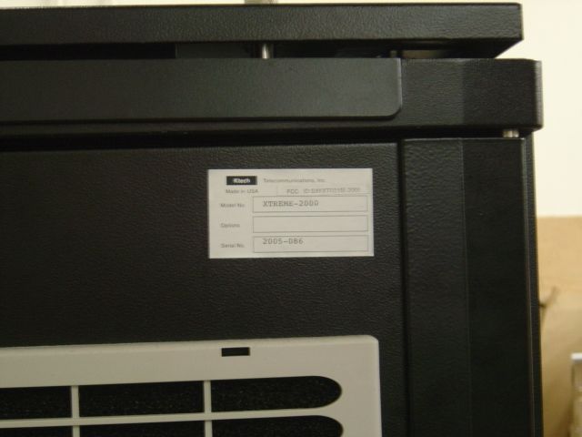
ID Label/Location Info
Serial No: Option No: Model No: KTECH TELECOMMUNICATIONS, INC. www.ktechtelecom.com FCC ID: SXKXTREME-2000
Internal Photos
XTREME-2000 INTERNAL CONSTRUCTION PHOTOGRAPHS XTREME-2000 REAR VIEW DOOR OPEN
Operational Description
February 25, 2005 FEDERAL COMMUNICATIONS COMMISSION OFFICE OF ENGINEERING AND TECHNOLOGY EQUIPMENT AUTHORIZATION BRANCH 445 12 ST. SW WASHINGTON, DC 20554 Dear Sir, This letter is to inform you that the Operational Description for the XTREME-2000 transmitter is contained in the user manual which has already been uploaded to the OET website. Sincerely, Gregory L. Best President Greg Best Consulting, Inc. 9223 N. Manning Ave. Kansas City, MO 64157 816-792-2913
Parts List/Tune Up Info
February 25, 2005 FEDERAL COMMUNICATIONS COMMISSION OFFICE OF ENGINEERING AND TECHNOLOGY EQUIPMENT AUTHORIZATION BRANCH 445 12 ST. SW WASHINGTON, DC 20554 Dear Sir, This letter is to inform you that the parts list/tune up info for the XTREME-2000 transmitter is contained in the user manual which has already been uploaded to the OET website. Sincerely, Gregory L. Best President Greg Best Consulting, Inc. 9223 N. Manning Ave. Kansas City, MO 64157 816-792-2913
Test Report
TEST REPORT K-TECH TELECOMMUNICATIONS XTREME-2000 DTV TRANSMITTER TECHNICAL REPORT INTRODUCTION The following information is provided to support the technical performance of the K-TECH Telecommunications XTREME-2000 TV Transmitter. The information is supplied for DTV broadcast service according to applicable portions of FCC rules contained in Part 2, Part 73, and Part 74. 1. Power Output Measurements as indicated by FCC Rule 74.795. 2. Frequency Measurements as identified by FCC Rule 74.795. 3. Emission mask compliance as defined in FCC Rule 74.794. 4. Attenuation to harmonics produced in the RNSS bands as defined in FCC Rule 74.794 5. Measurement of cabinet radiation of spurs and harmonics as specified in FCC Rule 2.1053 and 2.1057. 6. Demonstration of transmission and reception of 8-VSB ATSC signal. 7. Measurements of voltage and current to final amp stage as outlined in FCC Rule 74.795. Measurements were conducted at transmitter power output levels of 100 watts average and 25 watts average and constitute the range of power for which type certification is sought. Measurements were taken on a unit with operating on UHF TV channel 20. All test equipment was calibrated prior to the use of the equipment by the supplier of the test equipment. The list of test equipment is provided on the last page of the test report. RF POWER OUTPUT The equipment was configured as shown on the next page. The loss through the RF output cable, and attenuator was calibrated at the frequency of 506 MHz. The transmitter was energized and the power was increased to the desired output power. The average power was measured on the Agilent E4418 wattmeter equipped with an Agilent E4412A power sensor. The following pictures also indicate the power meter reading on the transmitter front panel. POWER OUTPUT MEASUREMENTS Power Meter Reading Power Meter Reading at high power =105 watts at low power= 23 watts TEST EQUIPMENT CONFIGURATION Dashed line indicates only one instrument connected at a time. XTREME-2000 UUT HP Power Meter RFA 300A Spectrum Analyzer RF input 50 dB Attenuator FIGURE 1 FREQUENCY STABILITY MEASUREMENTS Frequency stability versus temperature and line voltage was measured in a controlled environment. For these tests the exciter RF output was fed to an Agilent E4403B spectrum analyzer with built-in frequency counter that has better than a 1ppm accuracy. The test equipment configuration is shown below. Frequency Stability versus line voltage variation Frequency Stability versus temperature The Variac was adjusted for nominal voltage and the frequency was recorded. Then the variac was adjusted to 85% and 115% of the nominal voltage and the frequency was recorded at each voltage level. The results are tabulated below. LINE VOLTAGE (Volts) Pilot Frequency (MHz) 180 (85%) 506.309197 212 (nominal) 506.309200 244 (115%) 506.309204 For the temperature stability measurements the exciter was placed inside a Wedco Model 22-17MM temperature chamber equipped with a temperature controller. The exciter frequency was measured on the spectrum analyzer. Measurements were first recorded at room temperature (23 °C). The temperature in the chamber was raised to a maximum of 40 °C. Then the temperature was lowered to the minimum temperature of 0 °C. The temperature in the chamber was changed to each of the points identified in the table below and measured at the times indicated. The chamber followed a prescribed rate of change to reach each temperature and was then allowed to stabilize at the desired temperature for 10-15 minutes at which time frequency measurements were made. Temperature °C Time Pilot Frequency (MHz) 23 11:00 506.309125 30 11:25 506.309124 40 11:50 506.309107 20 12:30 506.309184 10 12:45 506.309288 0 1:00 506.309340 The recorded data indicates that the total frequency shift was 233 Hz which meets the FCC stability requirements. Exciter Agilent E4403B S.A. Variac AC Input AC OutputRF Output Exciter Agilent E4403B S.A. Temperature Chamber RF Output EMISSION MASK The transmitter was tested to determine compliance with the “stringent” emission mask as defined in the FCC rules. The test equipment was configured as shown in Figure 1. The transmitter was energized on channel 20 and the emissions from the transmitter were measured at 100 watts output power and at 25 watts output power using a Tektronix RFA 300A and graphs of each performance measurement were made and are recorded below. RF POWER OUTPUT AT 100 WATTS RF POWER OUTPUT AT 25 WATTS HARMONIC AND SPURIOUS MEASUREMENTS The equipment configuration of Figure 1 was used to measure the harmonics. A photograph of the spectrum analyzer screen and the measurement method follows. The FCC rule specifies that all harmonics and spurious shall be -76 dB with respect to the total power in the authorized channel. In a 500 kHz resolution bandwidth, the flat part of the spectrum will be 10.6 dB lower than the total power within the channel and therefore any harmonic energy will need to be 76-10.6 = 65.4 dB below the flat portion of the spectrum. Because of the “noiselike” characteristic of the DTV waveform both fundamental and harmonic/spurious energy will be reduced by an equal amount when adjusting the resolution bandwidth function of a spectrum analyzer. So the measurement can be made in different resolution bandwidth than 500 kHz and as long as the energy is below -65.4 dB, this will meet the FCC specification. Using that information, the spectrum analyzer was configured for a resolution bandwidth of 30 kHz and the flat portion of the DTV waveform in the authorized channel was set at 10 dB below the top of the screen to prevent the spectrum analyzer from being overloaded. The spectrum through the 10 th harmonic was scanned to see if there was any harmonic or spurious energy present. No energy was found above the level of -66.3 dB which was the limitation of the spectrum analyzer in this configuration. The photograph below illustrates the concept and shows the area of the…
Text truncated - open the document above for the full version.
Test Report
SUPPLEMENTAL TEST REPORT INFORMATION REGARDING POWER OUTPUT TESTS The following information is provided to describe the power output tests made for the XTREME-2000 DTV transmitter at power levels of 100 and 25 watts output power. The following block diagram was used to conduct power output tests. Power output was recorded on an Agilent power meter model E4418 power meter with model E4412A power sensor. The 40 dB attenuator was calibrated at the fundamental power. The transmitter was energized normally and adjusted for the indicated power. Photographs of the power meter were taken at the respective power levels of 105 watts and 23 watts and are displayed on the next page. TEST EQUIPMENT CONFIGURATION Dashed line indicates only one instrument connected at a time. XTREME-2000 UUT HP Power Meter RFA 300A Spectrum Analyzer RF input 40 dB Attenuator FIGURE 1 Power meter reading at 105 watts output power. Power output = 10.2 dBm + 40 dB (attenuator) 50.2 dBm =105 watts Power meter reading at 23 watts output power. Power output = 3.67 dBm + 40 dB (attenuator) 43.67 dBm =23 watts
Contact Information
Applicant
Steve Kuh(President)
Technical Contact
GREG BEST CONSULTING, INC.GREG BEST
[email protected]8167922913
9223 N. MANNING AVENUE · KANSAS CITY, Missouri · United States
Technical Specifications
| # | Rule Parts | Frequency Range | Power Output | Emission | Tolerance |
|---|---|---|---|---|---|
| 1 | 74 | 470 MHz - 806 MHz | 100 W | 6M00K1D | 1000.0000000000 Hz |