SYS-SOLRF Transmitter Module
DenMat Holdings, LLC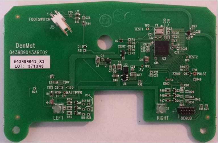
Click to zoom
Application Details
- Equipment Class
- DXX - Part 15 Low Power Communication Device Transmitter
- Date of Grant
- Jun 24, 2014
- Application Purpose
- Original Equipment
- Date of Application
- Jun 24, 2014
- Equipment Note
- RF Transmitter Module
- Frequency Range
- 2403.00000000 - 2473.00000000
- Company
- DenMat Holdings, LLC
- Country
- United States
Documents & Files
Document Text
Text extracted from the exhibit documents filed with the FCC. Open a document above to read the original.
Users Manual
Confidential and Proprietary Information ● DenMat Holdings, LLC ●1017 W. Central Ave., Lompoc, CA 93436‐2701 ●1‐800‐433‐6628 ●Page 1 USER’S MANUAL AND INSTALLATION GUIDE FOR DENMAT RF TRANSMITTER MODULE 033989500 Created on October 22, 2013 Confidential and Proprietary Information ● DenMat Holdings, LLC ●1017 W. Central Ave., Lompoc, CA 93436‐2701 ●1‐800‐433‐6628 ●Page 2 I. DESCRIPTION Denmat 033989500 RF Transmitter Module is a radio frequency transmitting device intended for integration into professional products requiring a wireless link. An example of the end product is a wireless Footpedal. This RF Transmitter Module, herein referred to as Module, does not contain the receiver necessary to complete the wireless link. It implements a one- way communications architecture. II. MODULE SPECIFICATIONS AND REQUIREMENTS a. Mechanical Specifications TOP VIEW DIMENSIONS Confidential and Proprietary Information ● DenMat Holdings, LLC ●1017 W. Central Ave., Lompoc, CA 93436‐2701 ●1‐800‐433‐6628 ●Page 3 - + TOP VIEW COMPONENT LOCATIONS 2-PIN HEADER J5 ACCEPTS PCB TRACE ANTENNA LOCATIONS. SWITCH CLOSURE INPUT KEEP CLEAR FOR BEST PERFORMANCE DC POWER INPUT PADS 2 LED INDICATORS WITH LIGHT FOR WIRE ATTACHMENT PIPES FOR STATUS DISPLAY Confidential and Proprietary Information ● DenMat Holdings, LLC ●1017 W. Central Ave., Lompoc, CA 93436‐2701 ●1‐800‐433‐6628 ●Page 4 BOTTOM VIEW PCB TRACE ANTENNA LOCATIONS SWITCH FOR KEEP CLEAR FOR BEST PERFORMANCE RECEIVER PAIRING CLEAR AREA DESIGNATED FOR OPTIONAL BATTERY PACK INSTALLATION Confidential and Proprietary Information ● DenMat Holdings, LLC ●1017 W. Central Ave., Lompoc, CA 93436‐2701 ●1‐800‐433‐6628 ●Page 5 b. Electrical Specifications Operating voltage range: 3.1VDC to 4.7VDC Operating current consumption: < 50mA (in active transmitting mode) Recommended power source: 3 primary AA size Alkaline or Lithium cells, 1.5V each (not included) Recommended battery holder module: keystone Electronics 2464 (not included) c. Switch Interface Specifications: The 2-pin header, J5, has the following interface specifications: Voltage sourced from this header: 3VDC nominal Current sourced out of this header: 1mA maximum Maximum switch resistance expected: 100 Ohms Manufacturer and part number for J5 header: Molex 0022122024 or equivalent Recommended mating connector: Molex 0022012027 housing Molex 0008550102 contacts or equivalent d. Environmental Specifications Operating temperature: 0ºC to +50ºC Storage temperature: -20ºC to +70ºC Relative Humidity: 10% - 95% RH non-condensing e. RF Communications Specifications The radio section of this module is categorized as an intentional transmitter within the unlicensed 2.4GZ ISM band. The details of communications protocol are described in a separate document which is available upon request from DenMat Holdings, LLC. The possible frequencies of operation are: Confidential and Proprietary Information ● DenMat Holdings, LLC ●1017 W. Central Ave., Lompoc, CA 93436‐2701 ●1‐800‐433‐6628 ●Page 6 Channel # Frequency [MHZ] 12403 22408 32413 42418 52423 62428 72433 82438 92443 102448 112453 122458 132463 142468 152473 There are 15 channels of normal operation and one channel specially assigned for transmitter-receiver pairing purposes. During the pairing process, both a new channel number and a new address are selected by this Module and get communicated to the external receiver. Each time it is paired with a receiver, the Module increases the frequency by 2 channels, meaning 10MHZ increments. The change is always in the ascending order and wraps around once the maximum normal operating channel number (channel 15) has been exceeded. For example, if starting at channel 1, then the following are the order of channel numbers every time pairing is performed: 1, 3, 5, 7, 9, 11, 13, 15, 2, 4, 6, 8, 10, 12, 14, 1, 3, ...... Confidential and Proprietary Information ● DenMat Holdings, LLC ●1017 W. Central Ave., Lompoc, CA 93436‐2701 ●1‐800‐433‐6628 ●Page 7 III. OPERATING INSTRUCTIONS a. Indicators: There are 2 LED indicators on the top side of the Module. The left one, D13, indicates RF transmission and pairing status while the right one, D15, indicates the power supply/battery level status. Here are the indication types and what they mean: LEFT SIDE LED (D13) SYMBOL COLOR SOLID/FLASHINGSTATE NONE SOLID OFF EITHER OF THE FOLLOWING : IN SLEEP MODE IN AWAKE MODE BUT WITH NO RF TRANSMISSIONS BLUE FAST FLASHING NORAML RF TRANSMISSIONS IN PROGRESS BLUE SLOW FLASHING PAIRING RF TRASMISSIONS IN PROGRESS RIGHT SIDE LED (D15) SYMBOL COLOR SOLID/FLASHINGSTATE NONE SOLID OFF IN SLEEP MODE AND BATTERY LEVEL IS NOT LOW GREEN SOLID ON IN AWAKE MODE AND BATTERY LEVEL IS HIGH YELLOWSOLID ON IN AWAKE MODE AND BATTERY LEVEL IS MEDIUM RED FAST FLASHING IN AWAKE MODE AND BATTERY LEVEL IS LOW RED SLOW FLASHING IN SLEEP MODE AND BATTERY LEVEL IS LOW Confidential and Proprietary Information ● DenMat Holdings, LLC ●1017 W. Central Ave., Lompoc, CA 93436‐2701 ●1‐800‐433‐6628 ●Page 8 b. Pairing With a Receiver: i. The receiver (a separate unit not supplied with this module) must be put into Pairing mode in order to start the pairing process. This means that it must be on the particular pairing frequency and pairing address as specified by this Module. ii. Then, the pairing button on this Module must be pressed continuously until the left side indicator starts flashing in blue color in slow speed. This usually takes about 1 second or longer. iii. Once the indicator has started flashing in blue, release the button and the Module will continually transmit Pairing packets for about 5 seconds. The pairing mode packets contain the new wireless address and new channel for the receiver to learn. At the end of the pairing mode, the Module will save the newly assigned channel and address in its non-volatile memory and then automatically goes to sleep mode. c. Sleep and Wakeups: The Module enters a low power sleep mode as soon as power is applied to it. In th…
Text truncated - open the document above for the full version.
Operational Description
RF Communications Specifications The radio section of this module is categorized as an intentional transmitter within the unlicensed 2.4GZ ISM band. The details of communications protocol are described in a separate document which is available upon request from DenMat Holdings, LLC. The possible frequencies of operation are: There are 15 channels of normal operation and one channel specially assigned for transmitter- receiver pairing purposes. During the pairing process, both a new channel number and a new address are selected by this Module and get communicated to the external receiver. Each time it is paired with a receiver, the Module increases the frequency by 2 channels, meaning 10MHZ increments. The change is always in the ascending order and wraps around once the maximum normal operating channel number (channel 15) has been exceeded. For example, if starting at channel 1, then the following are the order of channel numbers every time pairing is performed: 1, 3, 5, 7, 9, 11, 13, 15, 2, 4, 6, 8, 10, 12, 14, 1, 3, ...... Modulation: Gaussian Frequency-Shift Keying Occupied bandwidth (99%): 511 kHz No. of channels: 15
RF Exposure Info
SAR Exclusion Justification Test exclusion thresholds for 100 MHz to 6 GHz at test separation distances ≤ 50 mm Guidance document reference: 447498 D01 General RF Exposure Guidance v05r01, page 11, paragraph 4.3.1(1). The 1-g and 10-g SAR test exclusion thresholds for 100 MHz to 6 GHz at test separation distances ≤ 50 mm are determined by: [(max. power of channel, including tune-up tolerance, mW)/(min. test separation distance, mm)] * [√f(GHz)] ≤ 3.0 for 1-g SAR and ≤ 7.5 for 10-g extremity SAR, where • f(GHz) is the RF channel transmit frequency in GHz • Power and distance are rounded to the nearest mW and mm before calculation • The result is rounded to one decimal place for comparison • 3.0 and 7.5 are referred to as the numeric thresholds in the step 2 below The test exclusions are applicable only when the minimum test separation distance is ≤ 50 mm and for transmission frequencies between 100 MHz and 6 GHz. When the minimum test separation distance is < 5 mm, a distance of 5 mm according to 5) in section 4.1 is applied to determine SAR test exclusion. SAR test exclusion analysis: Assumptions: Since the exact separation distance may vary from sensor to sensor, the minimum separation distance of 5 mm is assumed per the guidance document. Max. power of channel:0.4mW Min. separation distance:5mm Max. frequency:2.48GHz [(Pwr/Dist)*√Freq.] =0.1 The result of the above SAR threshold calculation demonstrates that the result is less than the 1-g numeric threshold of 3 and the 10-g numeric threshold of 7.5. Conclusion: The above analysis shows that the evaluated device qualifies for exemption from SAR testing. Signed: David Light,Sr. Wireless Test Engineer 4/22/2014 Nemko USA, Inc.
Test Report
Nemko Test Report: 2014_246422_FCC_15249 Applicant: Den-Mat Holdings LLC 2727 Skyway Drive Santa Maria CA 93455 United States Equipment Under Test: SOL (E.U.T.) FCC Identifier: SYS-SOL Industry Canada Identifier: 11076A-SOL In Accordance With: FCC Part 15, Subpart C, 15.249 and Industry Canada RSS-210, Issue 8 Operation within the bands 902-928 MHz, 2400-2483.5 MHz, 5725-5875 MHz, and 24.0-24.25 GHz. Tested By: Nemko USA Inc. 2210 Faraday Ave. Suite 150 Carlsbad, CA 92008 TESTED BY: DATE: 31 January 2014 David Light, Wireless Engineer APPROVED BY: DATE: 18 March 2014 Bruce Ketterling, EMC Manager Total Number of Pages: 14 Nemko USA, Inc. CFR 47, PART 15, SUBPART C, Paragraph 15.249 Operation within the bands 902-928 MHz, 2400-2483.5 MHz, 5725-5875 MHz, and 24.0-24.25 GHz. EQUIPMENT: SOL REPORT NO.:2014_246422_FCC_15249 Page 2 of 18 Table Of Contents SECTION 1. SUMMARY OF TEST RESULTS 3 SECTION 2. GENERAL EQUIPMENT SPECIFICATION 5 SECTION 3. RADIATED EMISSIONS 6 SECTION 4. TEST EQUIPMENT LIST 15 ANNEX A TEST DIAGRAMS 16 Nemko USA, Inc. CFR 47, PART 15, SUBPART C, Paragraph 15.249 Operation within the bands 902-928 MHz, 2400-2483.5 MHz, 5725-5875 MHz, and 24.0-24.25 GHz. EQUIPMENT: SOL REPORT NO.:2014_246422_FCC_15249 Page 3 of 18 Section 1. Summary Of Test Results Manufacturer: Den-Mat Holdings LLC Model No.: SOL Serial No.: None General: All measurements are traceable to national standards. These tests were conducted on a sample of the equipment for the purpose of demonstrating compliance with CFR 47 Part 15.249 and Industry Canada RSS-210 Issue 8. All tests were conducted using measurement procedure ANSI C63.4-2003. Radiated Emissions were made on an open area test site. New Submission Production Unit Class II Permissive Change Pre-Production Unit THIS TEST REPORT RELATES ONLY TO THE ITEM(S) TESTED. THE FOLLOWING DEVIATIONS FROM, ADDITIONS TO, OR EXCLUSIONS FROM THE TEST SPECIFICATIONS HAVE BEEN MADE. See “ Summary of Test Data”. NVLAP Lab Code 200116-0 This report must not be used to claim product certification, approval, or endorsement by NVLAP, NIST, or any agency of the Federal Government. Nemko USA, Inc. is a NVLAP accredited laboratory. Nemko USA Inc. authorizes the above named company to reproduce this report provided it is reproduced in its entirety and for use by the company’s employees only. Any use which a third party makes of this report, or any reliance on or decisions to be made based on it, are the responsibility of such third parties. Nemko USA Inc. accepts no responsibility for damages, if any, suffered by any third party as a result of decisions made or actions based on this report. This report applies only to the items tested. Nemko USA, Inc. CFR 47, PART 15, SUBPART C, Paragraph 15.249 Operation within the bands 902-928 MHz, 2400-2483.5 MHz, 5725-5875 MHz, and 24.0-24.25 GHz. EQUIPMENT: SOL REPORT NO.:2014_246422_FCC_15249 Page 4 of 18 Summary Of Test Data NAME OF TEST PARA. NO. RESULT Conducted Emissions 15.207 / RSS-Gen 7.2.4 NA Radiated Emissions 15.249(a) / RSS-210 A2.9 Complies Receiver Spurious Emissions RSS-Gen 7.2.2 NA Footnotes For N/A’s: The transmitter is battery powered. The EUT operates above 960 MHz. Nemko USA, Inc. CFR 47, PART 15, SUBPART C, Paragraph 15.249 Operation within the bands 902-928 MHz, 2400-2483.5 MHz, 5725-5875 MHz, and 24.0-24.25 GHz. EQUIPMENT: SOL REPORT NO.:2014_246422_FCC_15249 Page 5 of 18 Section 2. General Equipment Specification Frequency Range: 2400 to 2483.5 MHz Operating Frequency(ies) of Sample: 2403 to 2473 MHz Number of Channels: 15 Modulation Type: GFSK Emissions Designator: 511KF1D Channel Spacing: 5 MHz Power Source: 4.5 Vdc (3 AAA batteries) User Frequency Adjustment: Manual Integral Antenna Yes No Nemko USA, Inc. CFR 47, PART 15, SUBPART C, Paragraph 15.249 Operation within the bands 902-928 MHz, 2400-2483.5 MHz, 5725-5875 MHz, and 24.0-24.25 GHz. EQUIPMENT: SOL REPORT NO.:2014_246422_FCC_15249 Page 6 of 18 Section 3. Radiated Emissions NAME OF TEST: Radiated Emissions PARA. NO.: FCC 15.249(a) RSS-210 A2.9 TESTED BY: David Light DATE: 25 November2013 Minimum Standard: (a) The field strengths shall not exceed the following: Carrier (MHz) Field Strength (mV/m) Field Strength (dBV) Harmonic (μV/m) Harmonic (dBV) 902-928 50 94 500 54 2400-2483.5 50 94 500 54 5725-5875 50 94 500 54 24000-24250 250 108 2500 68 (b) Field strength limits are specified at a distance of 3 meters. (c) Emissions radiated outside of the specified frequency bands, except for harmonics, shall be attenuated by at least 50 dB below the level of the fundamental or to the general radiated limits of 15.209 whichever is the less attenuation. (d) ...for frequencies above 1000 MHz, the above field strength limits are based on average limits. However, the peak field strength of any emission shall not exceed the maximum permitted average limits specified above by more than 20 dB under any condition of modulation. Test Results: Complies. The worst case emission was 47.3 dBμV/m at 2400 MHz. This is 6.7 dB below the specification limit. Measurement Data: See attached table(s). This device was tested with a fresh battery. This device was tested at +/- 15% input power with no variation in output power. This device was tested from 30 MHz to the tenth harmonic of the carrier. RBW=VBW=100 kHz < 1000 MHz Peak Detector RBW= 1 MHz / VBW=3 MHz > 1000 MHz Peak Detector Nemko USA, Inc. CFR 47, PART 15, SUBPART C, Paragraph 15.249 Operation within the bands 902-928 MHz, 2400-2483.5 MHz, 5725-5875 MHz, and 24.0-24.25 GHz. EQUIPMENT: SOL REPORT NO.:2014_246422_FCC_15249 Page 7 of 18 Test Data - Radiated Emissions (Peak) Low Channel Meas.Ant.DutyMeterAntennaPathRFCorrectedSpec.CR/SLPass Freq.Pol.CycleReadingFactorLossGainReadinglimitDif f .Fail (MHz)(H/V)(dB)(dBuV)(dB)(dB)(dB)(dBuV/m)(dBuV/m)(dB)Unc.Comment Low Channel 2403V087.724.59.041.479.8114.0-34.2PassCarrier 2403H097.224.59.041.489.3114.0-24.7PassCarrier 2400V06224.59.041.454.174.0-19.9Pass 2400H075.224.59.041.467.374.…
Text truncated - open the document above for the full version.
Contact Information
Applicant
Miles Hartfeld(Sr. Director of RA/QA)
Non-Technical Contact
Nemko USA, IncJenny Gibbs
[email protected]940-455-2246
Test Firm
Nemko USA, Inc. - San Diego EMC DivisionJan Blomgren
[email protected]760-444-3500
Technical Specifications
| # | Rule Parts | Frequency Range | Power Output |
|---|---|---|---|
| 1 | 15C | 2.40 GHz - 2.47 GHz | - |