T28SZFDADZGSFM Transmitter
Shenzhen Xinfuda Electronic Co., Ltd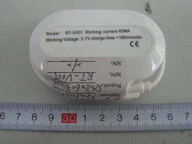
Click to zoom
Application Details
- Equipment Class
- DXX - Part 15 Low Power Communication Device Transmitter
- Date of Grant
- Apr 16, 2006
- Application Purpose
- Original Equipment
- Date of Application
- Apr 16, 2006
- Equipment Note
- FM Transmitter
- Frequency Range
- 88.10000000 - 107.90000000
- Country
- China
Documents & Files
Document Text
Text extracted from the exhibit documents filed with the FCC. Open a document above to read the original.
Users Manual
Features: This device can set up the digital plays, car or home audio systems wireless link quickly and easily. It only needs to connect the FM transmitter to your MP3 player, portable DVD, PDA, MD, CD, MP4, cassette player, PC, laptop or any other audio players. High fidelity stereo effect: this device can modulate the audio frequency signal to FM signal (88.1~107.9MHz). With the stereo tune you can enjoy listening high quality music anywhere. LCD display for easier control. Full frequency range design can effectively avoid interruption. Operation instruction: 1 Press the power button “ON/OFF” for a few seconds the LCD display shows “ON 88.1MHZ”, “88.1MHZ” is the transmission frequency.On the state of just power off, click the power button “ON/OFF”, the device will auto check transmission circuit. The device will default the transmission frequency setting before power off. 2 Plug the FM Transmitter into the audio device's output port, Adjust the volume and frequency of the FM radio (avoid the transmission points of the broadcasting stations) .Press the power button of the FM Transmitter, tune the transmission frequency, according to the reception frequency of the FM radio (If the FM signal is interrupted, please set the frequency of the FM Transmitter and the FM tuner to the other frequency) 3 click the “SCA N” or “SCA N” button to adjust 0.1MHz frequency up or down. Press the SCA N” or “SCA N” button for a few seconds, the device will adjust frequency automatically. 4 built-in rechargeable lithium battery, when LCD display shows“ ”, Please charge up the device. 5 Charge operating: Plug the charger (accessories) into cigarette lighter in your car, connect with the device. (Remark: charge time < 180 minutes). Specification: Operating range: >10m Operating current: 45mA Transmission range: 88.1 MHz -107.9MHz (interval 0.1MHz) Frequency response: 20-15000Hz Stereo Separation: 40dB Transmission Frequency Deviation: <0.1MHz Frequency stability range: ±10PPM Signal-to-Noise ratio: ≥68dB Caution: Changes or modifications to this unit not expressly approved by the party responsible for compliance will void the user’s authority to operate the equipment. Any change to the equipment will void FCC grant. NOTE: This equipment has been tested and found to comply with the limits for a digital device, pursuant to part 15 of the FCC Rules. These limits are designed to provide reasonable protection against harmful interference in a residential installation. This equipment generates, uses and can radiate radio frequency energy and, if not installed and used in accordance with the instructions, may cause harmful interference to radio communications. However, there is no guarantee that interference will not occur in a particular installation. If this equipment does cause harmful interference to radio or television reception, which can be determined by turning the equipment off and on, the user is encouraged to try to correct the interference by one or more of the following measures: --Reorient or relocate the receiving antenna. --Increase the separation between the equipment and receiver. --Connect the equipment into an outlet on a circuit different from that to which the receiver is connected. --Consult the dealer or an experienced radio/TV technician for help. This device complies with Part 15 of the FCC Rules. Operation is subject to the following two conditions: (1) this device may not cause harmful interference, and (2) this device must accept any interference received, including interference that may cause undesired operation.
Block Diagram
L R CRYSTAL 7.6MHz POWER PLL PREEMPHASISLCD CPU RF
External Photos
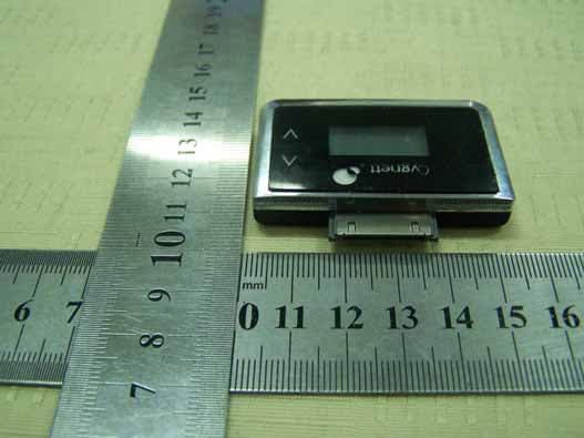
External Photos EUT Top View EUT Bottom View EUT Adapter View
ID Label/Location Info
ID Label Label FCC ID: T28SZFDADZGS
ID Label/Location Info
ID Label/Location Label Location Information Specifications: Text is Black or white in color and is left justified. Labels are printed in indelible ink on permanent adhesive backing or silk-screened onto the EUT or shall be affixed at a conspicuous location on the EUT. Refer to the below arrow.
Internal Photos
Internal Photos EUT – Inside View (1) EUT – Inside View (2) EUT –PCB View (1) EUT –PCB View (2) EUT –PCB View (3) EUT –Battery Front View EUT –Battery Rear View
Operational Description
Circuit Description: The main function of this circuit is miniature FM transmit, when audio signal is modulated to the best effect, input PLL and modulate stereo, then fm by PLL and oscillation frequency of PLL, finally transmit by RF.PLL oscillation frequency is controlled by CPU at the same time, CPU output controlled signal control the specific frequency of PLL, in addition the specific frequency will display in the LCD. The power of the circuit can be provided by lithium battery step-up to 5V, also can be provided by car 12V power step-down to 5V,or supplied by car 12V power change to 5V via DC-DC step-up to 5V.
Schematics
123 3 21 D C B A Tit Siz A Da Fil r-in 1 pre 2 lp f 3 f ilt er 4 out 5 d3 18 p ilo t 19 lp f 20 pre 21 l- in 22 U1BH R43 7033 46 45 4241403638373935343332313029 26 25 24 23 22 21 20 19 18 17 16151413121110987654321 56 55 54 53 52 51 50 49 48 47 27 28 43 44 57 58 U6 LCD1 12345 U3 LM2576 L1 220uH D1 1N5822 C4 220uF/16V C6 47 u C6 220uF/16V C78 220uF/16V C37 104 C7 220 C7 104 C5 104 C4 220 C11 471 C8 151 C5 151 R50 4.7K R47A 1K R5 24K 5V 12V D1 0 M501C U2 7810 10V +5V D2 1N4007 +5V ce clock data C9 102 C3 105 C10 102 C12 105 C13 105 C1 105 R6 56K R4 56K R3 24K R12 8.2K R44 4.7K L9 L10 C76 104 L R Q1 0 9012 S1S3S2 LED1 C77 220uF/16V Por t1 +5V 1 2 3 4 USB1 R3100K R2100K 5V R13 10R R14A 820K R21 10K C70 104 C71 102 C72 104 C73 47uF/16V C8A 104 +5V A B C A BC BAT1 3.7V L8 100uH D9 1N5819 C74 220uF/16V C75 104 4 A B C D 4 Titl e Nu mberRev i sio nSize A4 Date:24-Mar-2006Sheet of File:E:\ \ \zfp.DdbDrawn By: lp f 3 f ilt er 4 out 5 gnd 6 pll-o 7 vcc 8 rf osc 9 rf gnd 10 rf out 11 p ll v cc 12 osc0 13 osc1 14 ce 15 clock 16 data 17 d3 18 p ilo t 19 lp f 20 U1BH1415F C6 47uF/16V C22 100uF/16V C52 47uF/16V C16 106 C7 220 C4 220 C11 471 C8 151 C5 151 C24 102 C26 104 L12 0R ceclockdata C5123 104 C27 27p C28 27p C34 10p Y1 7.6MHz R28 33K R9 2.2K C31 20K R8 100R R1 20K R12 8.2K R7 3.6K R11 10K R103.6K Q7 2SC3355 L7 82nH C53 R47 C17 331 C15 473 C21 101 C32 33p C14 102 C2 105 C20 C C18 105 C33 102 D1 KV-1471 LI 68nH Q5 2142 Port1 /16V
Test Report
Note: The test report is specially limited to the above company and this particular sample only. It may not be duplicated without prior written consent of Bay Area Compliance Lab Corp. (ShenZhen). This report must not be used by the client to claim product certification, approval, or endorsement by NVLAP, NIST or any agency of the US Government. FCC PART 15.239 EMI MEASUREMENT AND TEST REPORT For SHENZHEN XINFUDA ELECTRONIC CO., LTD 3F,Room 3321,International Electronics Building,Huaqiang North Road, Futian Dist,Shenzhen,China FCC ID: T28SZFDADZGS May 12, 2006 This Report Concerns: Original Report Equipment Type: FM Transmitter Test Engineer: Kamn Hu Report No.: RSZ06030206a Test Date: March 16, 2006-May 12, 2006 Reviewed By: Chris Zeng Prepared By: Bay Area Compliance Lab Corp. (ShenZhen) 6/F, the 3rd Phase of WanLi Industrial Building, ShiHua Road, FuTian Free Trade Zone, ShenZhen, Guangdong 518038, P.R.China Tel: +86-755-33320018 Fax: +86-755-33320008 SHENZHEN XINFUDA ELECTRONIC CO.,LTD FCC ID: T28SZFDADZGS Report # RSZ06030206a .doc Page 2 of 20 FCC Part 15.239 Test Report TABLE OF CONTENTS GENERAL INFORMATION.......................................................................................................................................3 PRODUCT DESCRIPTION FOR EQUIPMENT UNDER TEST (EUT) ....................................................................................3 OBJECTIVE...................................................................................................................................................................3 RELATED SUBMITTAL(S)/GRANT(S).............................................................................................................................3 TEST METHODOLOGY..................................................................................................................................................3 TEST FACILITY.............................................................................................................................................................3 LOCAL SUPPORT EQUIPMENT LIST AND DETAILS........................................................................................................4 EXTERNAL I/O CABLE..................................................................................................................................................4 SYSTEM TEST CONFIGURATION ..........................................................................................................................5 JUSTIFICATION.............................................................................................................................................................5 EUT EXERCISE SOFTWARE..........................................................................................................................................5 SPECIAL ACCESSORIES.................................................................................................................................................5 EQUIPMENT MODIFICATIONS.......................................................................................................................................5 CONFIGURATION OF TEST SETUP.................................................................................................................................6 BLOCK DIAGRAM OF TEST SETUP................................................................................................................................6 SUMMARY OF TEST RESULTS ...............................................................................................................................7 §15.209/§15.35/§15.239- RADIATED EMISSION......................................................................................................8 MEASUREMENT UNCERTAINTY....................................................................................................................................8 EUT SETUP..................................................................................................................................................................8 EMI TEST RECEIVER SETUP.........................................................................................................................................9 TEST EQUIPMENT LIST AND DETAILS...........................................................................................................................9 TEST PROCEDURE........................................................................................................................................................9 CORRECTED AMPLITUDE & MARGIN CALCULATION...................................................................................................9 TEST RESULTS SUMMARY............................................................................................................................................9 TEST DATA................................................................................................................................................................10 PLOT(S) OF TEST DATA..............................................................................................................................................11 §15.239 –BAND-EDGE AND OCC. B/W ..................................................................................................................18 MEASUREMENT UNCERTAINTY..................................................................................................................................18 TEST PROCEDURE......................................................................................................................................................18 TEST EQUIPMENT LIST AND DETAILS.........................................................................................................................18 TEST DATA.......................................................................................................…
Text truncated - open the document above for the full version.
Test Setup Photos
Test Setup Photos Radiated Emission - Front View Radiated Emission - Rear View
Contact Information
Applicant
Alex Deng
Test Firm
Bay Area Compliance Laboratory Corp. (Shenzhen)John Chan
Technical Specifications
| # | Rule Parts | Frequency Range | Power Output |
|---|---|---|---|
| 1 | 15C | 88.1 MHz - 107.9 MHz | - |
Other Applications from Shenzhen Xinfuda Electronic Co., Ltd
T28-CYAGSFM
Jan 20, 2008FM TRANSMITTER
Equipment Class
DXX - Part 15 Low Power Communication Device Transmitter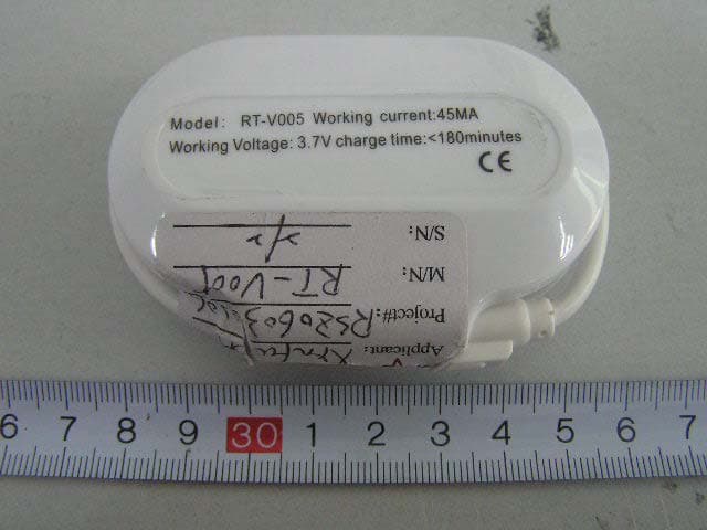
T28SZFDAZGS
Apr 02, 2006FM Transmitter
Equipment Class
DXX - Part 15 Low Power Communication Device Transmitter