T2CUSBW0001USB Wireless Phone
YEALINK (XIAMEN ) NETWORK TECHNOLOGY CO., LTD.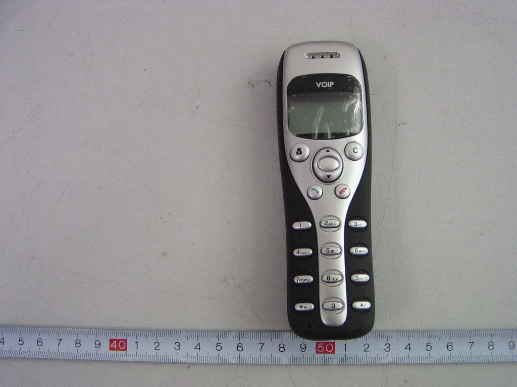
Click to zoom
Application Details
- Equipment Class
- DXX - Part 15 Low Power Communication Device Transmitter
- Date of Grant
- Jun 20, 2006
- Application Purpose
- Original Equipment
- Date of Application
- Jun 20, 2006
- Equipment Note
- USB Wireless Phone
- Frequency Range
- 2402.20000000 - 2480.20000000
- Country
- China
Documents & Files
Document Text
Text extracted from the exhibit documents filed with the FCC. Open a document above to read the original.
Users Manual
1. Instruction 1.1 Summary The W1D is a wireless Skype phone which is composed of one base and one handset. The base is a high quality speakerphone, ideal for conference calls. The handset has blue backlighted graphic LCD. Both base and handset ring for incoming calls. You can make/receive a call via the handset without the limitation of USB cable, just like using a mobile 1.2 Features 1. 2.4G USB wireless phone for Skype 2. 2.4GHz ISM Band, suit for Europe,USA,Japan etc. 3. Handfree with digital echo cancellation 4. Large graphic LCD with blue backlight 5. Review Skype contacts and call list on handset LCD 6. Both base and handset ring for all incoming calls. 7. Multi-language caller ID display feature 8. Auto-select RF channel to improve the quality of voice 1.3 Technical Data Standby time: More than 100 hours Talk time: More than 10 hours Radio range: 10 meters(32ft) Battery: 250mAh(Li-battery) 1 1.4 System Requirements 1. Windows 2000 or XP 2. 400MHz processor and free USB1.1 or USB2.0 port 3. 128MB RAM and 15MB free disk space 4. Any broadband connection or minimum 33.6 Kbps dialup 1.5 Package Contents 1. One handset 2. One base 3. One user manual 4. One installation CD 5. One USB VoIP phone’s bridge 2 Using the USB VoIP Phone 2.1 Phone’s Keypad Instruction : Contacts (1) Press to display the contacts list, press / to scroll the contacts list. (2) Press to call the friend displayed on the LCD. (3) Press to go back to idle. (4) The contacts are sorted by the first character of their names. e.g. Pressing “5” ,you will see all contacts starting with “J”. Pressing the “5” second time, you can see all contacts starting with “K” C: (1) Press to clear any number you input. (2) Press to switch between the Tabs of the Skype software. (3) During a call, you can press “ C ” to enable mute, press “ C ” again to disable mute / : Up/Down Press / to scroll call/contact list and to adjust volume when talking. 2 3 : Dial/Answer (1) Call out or answer a call. (2) Press to put call on hold, release call by pressing : Hang up (1) Hang up a call or refuse incoming call. (2) Press the key to go back to previous menu. : Press to input “+” at idle state, else input “*”. : Press to scroll ring style at idle state, else input “#”. 0-9: Digital keys (1) Press to input digital numbers. (2) Press to send DTMF message while talking. 2.2 Base station’s Instruction : Handsfree Key (1) Press to active handsfree. (2) Press to registrate phone to the base station. Speaker light: (1) During a call via handset, pressing the Handsfree key, the speaker light will flash. (2) The speaker light will be on during handsfree, otherwise off. Charge light: Place the handset in the base stat ion, the charge light will show two statuses: (1) When the phone’s battery is full, the light will be on. (2) When the Phone’s battery is flat, the light will flash. 2.3 Hardware installation 2.3.1 Connecting your base station to your PC When you connect your base stati on to your PC with USB cable, the LCD shows . 2.3.2 Registration Phone to the base station If the LCD shows : ,that indicates the handset has not registered to the base station .Please do the following steps: (1)Press and hold “ C ” on the handset(approx.3 secs.) and the LCD screen may display three beelines. 4 5 (2) Press and hold the handsfree key(approx.3 secs) The phone can come back to idle and the keyboard is valid. 2.4 Run Skype Download Skype software and install it (www.skype.com). The version must be 1.0.0.106 or higher. Run Skype and log in with Skype account. You can create a Skype account as shown below: After software startup, the icon will appear to the system tray as shown below: That indicates the Skype are successfully connected to Internet. If the icon is shown as , you have to check your Internet connection. 2.5 Run SkypeMate Insert SkypeMate installation CD or download SkypeMate software, then install it. Run SkypeMate Double-click the icon on the desktop, the Skype program will pop up the window as shown below: Select the first option “Allow this program to use Skype”, click “ OK ” button. Note: If you selecte the wrong option, you can make another selection. Please see 2.8. FAQ /problem4 for detail. After running SkypeMate, the icon will appear to the system tray as shown: 6 7 That indicates the device and Skype are connected successfully. If the icon shown as (the phone is green and the outside is grey), please run Skype first. If the icon shown as (the phone is red and the outside is green), it means USB VoIP Phone is connected incorrectly. Please reconnect USB VoIP Phone to PC. 2.6 Make a Call 2.7.1 Call Skype user from contacts Press to display contacts. Press / to select a contact. Press to call out. 2.7.2 Call Skype user from PC Contacts Go back to idle, press “ C ” to switch Skype software to “Contacts” Tab. Press / to select a contact. Press to call out. 2.7.3 Call Skype user from call list Go back to idle, press / to display the call list. Press / again to select a contact. Press to call out. 2.7.4 Call Skype user by Speed-Dial Add a friend (for example: bbc456) to Contacts Assign Speed-Dial for it, example "11" Input number and call out: Press digital "11" on USB VoIP Phone, then press to call out. 2.7.5 Call to regular phone Press "00" + "country number" + "phone number", then press . 8 9 Example: call someone in Beijing, China, please press 00861012345678, and then press . 0086 10 12345678 ---------------- ---------- -------------------- country code city code destination number Note: (1) You can input “+” instead of “00”. (3) If you want to use this function, you should buy SkypeOut Credit from www.skype.com first. 2.7.6 Activating Handsfree while making a call With the handsfree function instead of holding the handset to your ear, it can be put on the table in front of you to allow others to participate in the call. Enter the number from the phone’s keyboard and press to call out. Press the Handsfree key,.The speaker light will flash. Place…
Text truncated - open the document above for the full version.
Block Diagram
1 . Frequency : 2.402 —— 2.480GHZ 2 . Modulation : GFSK 3 . Block diagram : HANDSET : ANTENNA 2.402-2.480GHz Filter DEA252400BT-2023A1 DESKTOP PHONE ANTENNA 2.402-2.480GHz
External Photos
EXHIBIT B - EUT EXTERNAL PHOTOGRAPHS Base – Front View Base – Rear View Handset – Front View Handset – Rear View
ID Label/Location Info
EXHIBIT A - FCC ID LABELING AND LOCATION Proposed FCC ID Labeling Proposed FCC ID Location Rear Side of EUT / Proposed Label Location FCC ID: T2CUSBW0001
Internal Photos
EXHIBIT C - EUT INTERNAL PHOTOGRAPHS Base – Inside View (1) Base –Inside View (2) Base – Main PCB Top View Base –Main PCB Bottom View Handset – Inside View (1) Handset –Inside View (2) Handset –PCB Top View Handset –PCB Bottom View Handset – USB PCB Top View Handset –USB PCB Bottom View Handset – Battery Uncovered View
Operational Description
W1D CIRCUIT DESCRIPTION A:handset 1. Power supply:used 3.7V/250maH LI-ION battery。 2. 3.3V issued by XC6206 regulator ICs, supply to all circuit consume。 3. The NRF2401 2.4GHz RF transceiver with embedded 8051 compatible micro-controller and 9 input, 10 bit ADC, it performs the date modulation and demodulation, and transmit/receive date via antenna 4. The HT48R10A scans the keypad and control display. At the same time ,the HT48R10A communicate with NRF24E1. 5. The NRF2401 2.4GHz RF transceiver with embedded 8051 compatible micro-controller and 9 input, 10 bit ADC, it performs the date modulation and demodulation, and transmit/receive date via antenna B:desktop phone 1. Power supply:used USB power。 2. 5V supply to LM386(operation amplifier)。3.3V issued by XC6206 regulator ICs, supply to other circuit consume。 3. The NRF2401 is a single-chip radio transceiver for the world wide 2.402-2.4835GHz ISM band. The NRF24E1 communicates with HANDSET via antenna, NRF2401 receives the date and send it to CY7C68013, then the CY7C68013 management this data. 4. The CY7C68013 is a Single-chip integrated USB 2.0 transceiver, SIE, and enhanced 8051 microprocessor. It is a High-speed USB Peripheral Controller. It controls its peripheral, including keyboard, LED, MC14LC5481, and so on. CY7C68013 sends the data to PC software, then the PC software manager the data. 5. The MC145481 is a general purpose per channel PCM Coder-filer, this device performs the voice digitization and reconstruction. The MC145481 decodes the data from MSM7602 and send it to LM386(operational amplifier). The MC145481 codes the data from MIC and send to MSM7602. The MSM7602 is a low-power CMOS IC device for canceling echo (in an acoustic system or telephone line) generated in a speech path. The MSM7602 processes the coded sound data to cancel echo.
Schematics
123456 A B C D 654321 D C B A Title NumberRevisionSize B Date:9-Jun-2006 Sheet of File:E:\\work\USB-W1D\USB-W1D.DdbDrawn By: KROW8 S42S44 S33 S43 S35 S25S24 S32 S14S13 S22S23 *0# 789 456 123 KROW5KROW6KROW7 S11 S31 S21 S12 S41 KROW0 KROW1 KROW2 KROW3 KROW4 R44 39K R45 39K R43 39K R46 39K S45 DEL DOWN UP END SEND TAB /CS1 1 /RES 2 D/C 3 SCL 4 SDA 5 VDD 6 VSS 7 VEE 8 C3N 9 C1P 10 C1N 11 C2N 12 C2P 13 VL2 14 VL3 15 VL4 16 VL5 17 VL6 18 LCD HD10448 C70 105 C61 105 C62 105 C63 105 C64 105 C65 105 C66 105 C67 105 C68 105 C69 105 +3.3V BZ1 SFP-1250P +3.3V 1 2 BATTERY BATTERY +5V VBAT E11 100UF/10V C11 104 E13 10UF/10V C13 104 R12 300K 1% R13 120K 1% C14 104 R57 10K LED1 LED +3.3V Q53 8050 R58 10O Vin 2 GND 1 Vout 3 U1 XC6206+3.3V C12 104 VDD 1 AINO 2 DVDD2 3 P1.0 4 P1.1 5 P0.0 6 P0.1 7 P0.2 8 P0.3 9 P0.4/INT 10 P0.5 11 P0.6 12 P0.7 13 DVDD 14 VSS 15 XC2 16 XC1 17 VDD_PA 18 ANT1 19 ANT2 20 VSS_PA 21 VDD 22 VSS 23 AIN7 24 AIN6 25 AIN5 26 IREF 27 AREF 28 AIN4 29 ANI3 30 VSS 31 VDD 32 VSS 33 AIN2 34 AIN1 35 P1.2 36 U3 NRF24E1 R20 10K R21 20K C17 470PR23 1K R24 1.2KR25 62K R22 51K R26 10K C20 470P C23 104 C19 105 C21 105 E52 10UF/10V R27 1K MIC_IN BCLK FST(FSR) DT DR C25 104 E21 10UF/10V +3.3V VAGRef 1 RO- 2 PI 3 PO- 4 PO+ 5 VDD 6 FSR 7 DR 8 BCLKR 9 PDI 10 MCLK 11 BCLKT 12 DT 13 FST 14 VSS 15 Mu/A 16 TG 17 TI- 18 TI+ 19 VAG 20 U2 MC145481 +3.3V +3.3V R33 200K C26 822 C18 104 CS# 1 SO 2 WP# 3 GND 4 SI 5 SCK 6 HOLD# 7 VDD 8 U4 AT25320 PB5 1 PB4 2 PA3 3 PA2 4 PA1 5 PA0 6 PB3 7 PB2 8 PB1/BZ# 9 PB0/BZ 10 VSS 11 PC0/INT# 12 PC1/TMR 13 PC2 14 RES# 15 VDD 16 OSC1/PC3 17 OSC2/PC4 18 PA7 19 PA6 20 PA5 21 PA4 22 PB7 23 PB6 24 U5 HT48R10A R47 39K XT1 4.096MHZ C53 12P C52 12P R55 100K R54 10K C55 103 C54 104 +3.3V C24 104 XT2 16MHZ C42 18P C43 18P C38 1 C39 1 L323.6NH C37 1.5 ANT L31 22NH C35 222 C36 22 R31 22K C32 102 C33 103 +3.3V C34 333 R42 10K R41 10K E31 10UF/10V E51 10UF/10V C31 103 C51 104 C41 103 E12 10UF/10V +3.3V D11 1N4148 R32 1M 1 2 CHARGERB CHARGERB C40 102 C47 102 C46 104 C45 102 R34 51K R49 1K R52 10K R50 1K R59 10K +3.3V L33 0 C22 104 MIC MK1 SPK1 A 1 B 2 C 3 D 4 E 5 CON2 PHONEJACK STEREO SW C29 102 E4 10UF/10V R6 47O E41 470uF/10V R14 39K R16 39K +5V PA7 PA7 +3.3V R15 22K Q51 8050 12 kj JP R63 47 R62 47 R61 1M R17 4.7 R51 47 R53 1K ANTENNA IN 1 OUT 2 GND 4 GND 3 L1 DEA252400BT-2023A1 123456 A B C D 654321 D C B A Title NumberRevisionSize B Date:9-Jun-2006 Sheet of File:E:\\work\USB-W1D\USB-W1D.DdbDrawn By: 1 2 3 4 CN2 USB +5V E91 100UF/10V C95 104 Vin 2 GND 1 Vout 3 U9 XC6206+3.3V C96 104 RESET XT3 24MHZ C75 12P C74 12P R72 100K +3.3V +3.3V C73 104 E71 10UF/10V C71 104 C72 104 R71 100K RDY0/*SLRD 1 RDY1/*SLWR 2 AVCC 3 XTALOUT 4 XTALIN 5 AND 6 AVCC 7 DPLUS 8 DMINUS 9 AGND 10 VCC 11 GND 12 IFCLK 13 RESERVED 14 SCL 15 SDA 16 VCC 17 PB0/FD0 18 PB1/FD1 19 PB2/FD2 20 PB3/FD3 21 PB4/FD4 22 PB5/FD5 23 PB6/FD6 24 PB7/FD7 25 GND 26 VCC 27 GND 28 CTL0/*FLAGA 29 CTL1/*FLAGB 30 CTL2/*FLAGC 31 VCC 32 PA0/INT0# 33 PA1/INT1# 34 PA2/*SLOE 35 PA3/*WU2 36 PA4/FIFOADR0 37 PA5/FIFOADR1 38 PA6/*PKTEND 39 PA7/*FLAGD/SLCS# 40 GND 41 RESET# 42 VCC 43 WAKEUP 44 PD0/FD8 45 PD1/FD9 46 PD2/FD10 47 PD3/FD11 48 PD4/FD12 49 PD5/FD13 50 PD6/FD14 51 PD7/FD15 52 GND 53 CLKOUT 54 VCC 55 GND 56 U7 CY7C68013(56QFN) A0 1 A1 2 A2 3 VSS 4 SDA 5 SCL 6 WP 7 VCC 8 U6 AT24C64A R64 2.2K R67 2.2K C60 104 R65 10K R66 10K WP +3.3V SCL SDA USBD+ USBD- XT4 16MHZ C92 18P C93 18P C88 1 C89 1 L823.6NH L8122NHC85 222 C86 22 R81 22K C82 103 C81 102 C94 10UF/10V CE 1 DR2 2 CLK2 3 DOUT2 4 CS 5 DR1 6 CLK1 7 DATA 8 DVDD 9 VSS 10 XC2 11 XC1 12 VDD_PA 13 ANT1 14 ANT2 15 VSS_PA 16 VDD 17 VSS 18 IREF 19 VSS 20 VDD 21 VSS 22 PWR_UP 23 VDD 24 U8 NRF2401 R82 1M ANT +3.3V PWR CE CS DATA CLK1 DR1 1 2 CHARGERA CHARGERA LED2 GRE R83 10K Q83 8050 R85 10K C97 10UF/10V SW1 Pro R73 10K R74 1K L83 33UH Q71 8050 LED3 GRE +3.3V R77 1K R78 1K R75 1K +5V L71 0 L72 0 R120 10K R121 12K C117 470P R123 1K R124 1.2KR125 62K R122 51K R126 10K C120 470P C123 104 C119 105 C121 105 E152 10UF/10V R127 1K MIC_IN PCLK FST(FSR) DT DR C127 104 E121 10UF/10V +3.3V VAGRef 1 RO- 2 PI 3 PO- 4 PO+ 5 VDD 6 FSR 7 DR 8 BCLKR 9 PDI 10 MCLK 11 BCLKT 12 DT 13 FST 14 VSS 15 Mu/A 16 TG 17 TI- 18 TI+ 19 VAG 20 U12 MC145481 +3.3V+3.3V R133 200K C126822 C118 104 C122 104 MIC MIC2 SOUT_ECDT RIN_ECDR 7602_RST XT6 19.2Mhz NLP 1 HCL 2 ADP 3 VDD 4 ATT 5 INT 6 IRLD 7 SIN 8 RIN 9 SCK 10 SYNC 11 SOUT 12 ROUT 13 VSS 14 VSS 15 HD 16 X1 17 X2 18 VDD 19 PWDWN 20 VSS 21 SYNCO 22 SCKO 23 RST 24 WDT 25 GC 26 VDD 27 MCKO 28 U13 MSM7602 +3.3V +3.3V R131 1M R135 10K R137 10K C131 18P C132 18P R138 10K +3.3V R134 10K boGainCtrl R139 10K GAIN 1 -INPUT 2 +INPUT 3 GND 4 VOUT 5 VCC 6 BP 7 GAIN 8 U10 LM386 R104 1.2K E101 10UF/10V E102 220UF/10V R105 4.7C103 104 E10310UF/10V +5V SPK2 R101 500K R102 500K C101 104 C102 104 R103 100K R144 0 R143 0 C128 104 echo1 echo2 echo1 echo2 1 2 3 4 5 CONNECTA CONNECTA 1 2 3 4 5 CONNECTB CONNECTB +3.3V +3.3V /FSYNC R79 51 1 2 SPK2A SPK2A 1 2 MIC2A MIC2A C98 102 R76 1M 1 2 SPK2B SPK2B /FSYNC PCLK 1 2 MIC2B MIC2B FST(FSR) E104 100UF/10V C106 104 R107 10K C105 105 R106 10K C104 105 Q101 9014 Q102 8550 R108 51K HF CTRL HF CTRL Q72 8050 R70 1K NLP ADP ATT NLPADP ATT R136 10K ANTENNA IN 1 OUT 2 GND 4 GND 3 L2 DEA252400BT-2023A1
Test Report
Note: The test report is specially limited to the above company and this particular sample only. It may not be duplicated without prior written consent of Bay Area Compliance Lab Corp. (ShenZhen). This report must not be used by the client to claim product certification, approval, or endorsement by NVLAP, NIST or any agency of the US Government. FCC PART 15.249 EMI MEASUREMENT AND TEST REPORT For XIAMEN YEALINK NETWORK TECHNOLOGY CO., LTD. 7/F HuaLian Electronic BLDG., No.580 JiaHe Road, XiaMen, China FCC ID: T2CUSBW0001 June 8, 2006 This Report Concerns: Original Report Equipment Type: USB Wireless Phone Test Engineer: Deny Xiong Merry Zhao Report No.: RSZ06022001 Test Date: February 24-June 7, 2005 Reviewed By: Boni Baniqued Prepared By: Bay Area Compliance Lab Corp. (ShenZhen) 6/F, the 3rd Phase of WanLi Industrial Building, ShiHua Road, FuTian Free Trade Zone, ShenZhen, Guangdong 518038, P.R.China Tel: +86-755-33320018 Fax: +86-755-33320008 XIAMEN YEALINK NETWORK TECHNOLOGY CO., LTD. FCC ID: T2CUSBW0001 Report # RSZ06022001 Page 2 of 25 FCC PART 15.249 Report TABLE OF CONTENTS GENERAL INFORMATION.......................................................................................................................................3 PRODUCT DESCRIPTION FOR EQUIPMENT UNDER TEST (EUT) ....................................................................................3 OBJECTIVE...................................................................................................................................................................3 RELATED SUBMITTAL(S)/GRANT(S).............................................................................................................................3 TEST METHODOLOGY..................................................................................................................................................3 TEST FACILITY.............................................................................................................................................................3 HOST SYSTEM CONFIGURATION LIST AND DETAILS....................................................................................................4 LOCAL SUPPORT EQUIPMENT LIST AND DETAILS........................................................................................................4 EXTERNAL I/O CABLE.................................................................................................................................................4 SYSTEM TEST CONFIGURATION ..........................................................................................................................5 JUSTIFICATION.............................................................................................................................................................5 EUT EXERCISE SOFTWARE..........................................................................................................................................5 S PECIAL A CCESSORIES .................................................................................................................................................5 B LOCK D IAGRAM /S CHEMATICS ...................................................................................................................................5 E QUIPMENT M ODIFICATIONS .......................................................................................................................................5 CONFIGURATION OF TEST SETUP.................................................................................................................................6 BLOCK DIAGRAM OF TEST SETUP................................................................................................................................7 SUMMARY OF TEST RESULTS...............................................................................................................................8 §15.203 - ANTENNA REQUIREMENT......................................................................................................................9 STANDARD APPLICABLE..............................................................................................................................................9 §15.207 - CONDUCTED EMISSION ........................................................................................................................10 MEASUREMENT UNCERTAINTY..................................................................................................................................10 EUT SETUP................................................................................................................................................................10 EMI TEST RECEIVER SETUP......................................................................................................................................11 TEST EQUIPMENT LIST AND DETAILS.........................................................................................................................11 TEST PROCEDURE......................................................................................................................................................11 TEST RESULTS SUMMARY..........................................................................................................................................11 T EST D ATA ................................................................................................................................................................12 P LOT ( S ) OF T EST D ATA ..............................................................................................................................................12 §15.205 §15.209(A) §15.249(A) - RADIATED EMISSION ......................................................................................15 MEASUREMENT UNCERTAINTY....................................................................................................…
Text truncated - open the document above for the full version.
Test Setup Photos
EXHIBIT D - TEST SETUP PHOTOGRAPHS Conducted Emission - Front View Conducted Emission - Side View Base: Radiated Emission - Front View (Above 1 GHz) Base: Radiated Emission - Rear View (Above 1 GHz) Base: Radiated Emission - Front View (30 MHz-1 GHz) Base: Radiated Emission - Rear View (30 MHz-1 GHz) Handset: Radiated Emission - Front View (Above 1 GHz) Handset: Radiated Emission - Rear View (Above 1 GHz) Handset: Radiated Emission - Front View (30 MHz-1 GHz) Handset: Radiated Emission - Rear View (30 MHz-1 GHz)
Contact Information
Applicant
Stone Lu(Vice General Manager)
Test Firm
Bay Area Compliance Laboratory Corp. (Shenzhen)John Chan
Technical Specifications
| # | Rule Parts | Frequency Range | Power Output |
|---|---|---|---|
| 1 | 15C | 2.40 GHz - 2.48 GHz | - |
Other Applications from YEALINK (XIAMEN ) NETWORK TECHNOLOGY CO., LTD.
T2C-BHD862L
Aug 11, 2026Bluetooth Headset
Equipment Class
DTS - Digital Transmission SystemT2C-BHD862R
Aug 11, 2026Bluetooth Headset
Equipment Class
DTS - Digital Transmission SystemT2C-UVC86E2
Jun 24, 2026Video Conferencing Endpoint
Equipment Class
DTS - Digital Transmission SystemT2C-Z32X
Jun 04, 2026Bluetooth Headset
Equipment Class
DTS - Digital Transmission SystemT2C-BHD742V1
Dec 22, 2025Bluetooth Headset
Equipment Class
DSS - Part 15 Spread Spectrum Transmitter