T2I7559Bluetooth music receiver
foneGear, LLC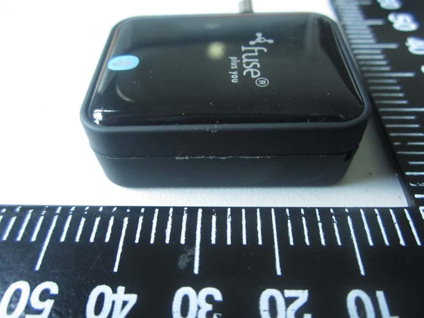
Click to zoom
Application Details
- Equipment Class
- DSS - Part 15 Spread Spectrum Transmitter
- Date of Grant
- Aug 24, 2014
- Application Purpose
- Original Equipment
- Date of Application
- Aug 24, 2014
- Equipment Note
- Bluetooth music receiver
- Frequency Range
- 2402.00000000 - 2480.00000000
- Company
- foneGear, LLC
- Country
- United States
Documents & Files
Document Text
Text extracted from the exhibit documents filed with the FCC. Open a document above to read the original.
Users Manual
This device complies with Industry Canada licence-exempt RSS standard(s). Operation is Subject to the following two conditions: (1) this device may not cause interference, and (2) this device must accept any interference, including interference that may cause undesired operation of the device. Le présent appareil est conforme aux CNR d'Industrie Canada applicables aux appareils radio exempts de licence. L'exploitation est autorisée aux deux conditions suivantes : (1) l'appareil ne doit pas produire de brouillage, et (2) l'utilisateur de l'appareil doit accepter tout brouillage radioélectrique subi, même si le brouillage est susceptible d'en compromettre le fonctionnement. FCC statements: This device complies with part 15 of the FCC rules. Operation is subject to the following two conditions: (1) this device may not cause harmful interference, and (2) this device must accept any interference received, including interference that may cause undesired operation. NOTE: The manufacturer is not responsible for any radio or TV interference caused by unauthorized modifications or changes to this equipment. Such modifications or changes could void the user’s authority to operate the equipment. NOTE: This equipment has been tested and found to comply with the limits for a Class B digital device, pursuant to part 15 of the FCC Rules. These limits are designed to provide reasonable protection against harmful interference in a residential installation. This equipment generates uses and can radiate radio frequency energy and, if not installed and used in accordance with the instructions, may cause harmful interference to radio communications. However, there is no guarantee that interference will not occur in a particular installation. If this equipment does cause harmful interference to radio or television reception, which can be determined by turning the equipment off and on, the user is encouraged to try to correct the interference by one or more of the following measures: - Reorient or relocate the receiving antenna. - Increase the separation between the equipment and receiver. -Connect the equipment into an outlet on a circuit different from that to which the receiver is connected. -Consult the dealer or an experienced radio/TV technician for help.
External Photos
External Photos 1. EUT front view 2. EUT rear view 3. EUT left side view 4. EUT right side view 5. EUT top view 6. EUT bottom view
ID Label/Location Info
FCC label and label location
Internal Photos
Internal Photos 1. EUT uncover view 2. Mainboard front view 3. Mainboard rear view 4. BT chip view 5. BT antenna view
Test Report
Report No.:SZ14060121W01 Shenzhen Morlab Communications Technology Co., Ltd Phone: +86 (0) 755 36698555 Web site: http://www.morlab.cn/ Fax: +86 (0) 755 36698525 Email: [email protected] Page 2 of 82 TABLE OF CONTENTS 1. GENERAL INFORMATION ...................................................................................................................... 5 1.1. EUT DESCRIPTION .................................................................................................................................. 5 1.2. TEST STANDARDS AND RESULTS ............................................................................................................. 6 1.3. FACILITIES AND ACCREDITATIONS ............................................................................................................ 7 1.3.1. FACILITIES ....................................................................................................................................................... 7 1.3.2. TEST ENVIRONMENT CONDITIONS ................................................................................................................ 7 2. 47 CFR PART 15C REQUIREMENTS ..................................................................................................... 8 2.1. ANTENNA REQUIREMENT ......................................................................................................................... 8 2.1.1. APPLICABLE STANDARD ................................................................................................................................. 8 2.1.2. RESULT: COMPLIANT ...................................................................................................................................... 8 2.2. NUMBER OF HOPPING FREQUENCY ......................................................................................................... 8 2.2.1. REQUIREMENT ................................................................................................................................................ 8 2.2.2. TEST DESCRIPTION ........................................................................................................................................ 8 2.2.3. TEST PROCEDURE ......................................................................................................................................... 9 2.2.4. TEST RESULT .................................................................................................................................................. 9 2.3. PEAK OUTPUT POWER ........................................................................................................................... 13 2.3.1. REQUIREMENT .............................................................................................................................................. 13 2.3.2. TEST DESCRIPTION ...................................................................................................................................... 13 2.3.3. TEST RESULT ................................................................................................................................................ 13 2.3.3.1. GFSK MODE ............................................................................................................................................. 14 2.3.3.2. ∏/4-DQPSK MODE ................................................................................................................................. 14 2.3.3.3. 8-DPSK MODE ......................................................................................................................................... 14 2.4. 20DB & 99% BANDWIDTH ...................................................................................................................... 15 2.4.1. DEFINITION ................................................................................................................................................... 15 2.4.2. TEST DESCRIPTION ...................................................................................................................................... 15 2.4.3. TEST PROCEDURE ....................................................................................................................................... 15 2.4.4. TEST RESULT ................................................................................................................................................ 16 2.4.4.1. GFSK MODE ............................................................................................................................................. 16 2.4.4.2. ∏/4-DQPSK MODE ................................................................................................................................. 20 2.4.4.3. 8-DPSK MODE ......................................................................................................................................... 23 2.5. CARRIED FREQUENCY SEPARATION ....................................................................................................... 27 2.5.1. DEFINITION ................................................................................................................................................... 27 2.5.2. TEST DESCRIPTION ...................................................................................................................................... 27 2.5.3. TEST PROCEDURE ....................................................................................................................................... 27 Report No.:SZ14060121W01 Shenzhen Morlab Communications Technology Co., Ltd Phone: +86 (0) 755 36698555 Web site: http://www.morlab.cn/ Fax: +86 (0) 755 36698525 Email: [email protected] Page 3 of 82 2.5.4. TEST RESULT ................................................................................................................................................ 28 2.6. TIME OF OCCUPANCY (DWELL TIME) .............…
Text truncated - open the document above for the full version.
Test Setup Photos
Test Setup Photos 1. Conducted emission main’s port front view 2. Conducted emission main’s port side view 3. Radiated emission (9KHz-30MHz) 4. Radiated emission (30MHz-1GHz) 5. Radiated emission (above 1GHz) 6. Conducted emission antenna’s port
Contact Information
Applicant
Shanni Novak(Director)
Test Firm
Shenzhen Morlab Communications Technology Co.,LtdShu Luan
Technical Specifications
| # | Rule Parts | Frequency Range | Power Output |
|---|---|---|---|
| 1 | 15C | 2.40 GHz - 2.48 GHz | 1.00 mW |
Other Applications from foneGear, LLC
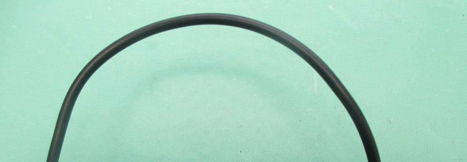
T2I-CXR002
Mar 10, 2014Bluetooth in-ear headphone
Equipment Class
DTS - Digital Transmission System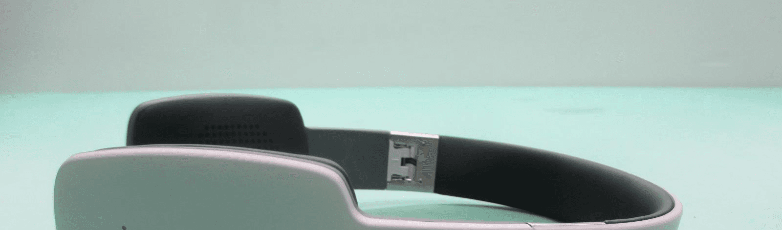
T2I-CXR003
Mar 09, 2014Bluetooth Headphone
Equipment Class
DSS - Part 15 Spread Spectrum Transmitter